

patent · US4016836A
Hydride fuel system
12 April 1977
Text
Page 1bibliographic recordscan →
MacKay et al.
54 HYDRIDE FUEL SYSTEM
(75) Inventors: Donald B. MacKay, Spanish Fork;
Brian C. Nielson; Dale L. Henriksen, both of Orem; Roger Evan Billings,
Provo; Harold M. Simons, Orem,
Paul P. Hindmarsh, Provo, all of
Utah (73) Assignee: Billings Energy Research
Corporation, Provo, Utah
(52) U.S.C. ................................................... 123/3 51 Int. Cl”......................................... F02B 43100
UNITED STATES PATENTS
3,291,572 12/1966 Fatica .................................. 23/281 3,313,598 4/1967 Gluckstein ...... ... 423/648 3,323,873 6/1967 Horn et al. .......................... 23/281 3,648,668 3/1972 Pacheco ................................ 123/3 3,676,071 7/1972 Speed ................................ 423/648 3,709,203 1/1973 Cettin et al. ....................... 123/3 X 3,717, 29 2/1973 Fox .................................... 123/1 A 3,734,863 5/1973 Beckert et al. ................ 423/648 X Primary Examiner-Charles J. Myhre
Assistant Examiner-William C. Anderson
Attorney, Agent, or Firm-Criddle, Thorpe & Western
A hydride fuel system is disclosed for use with a motor vehicle or other apparatus having a combustion unit and a mixing device for mixing hydrogen gas with air for introduction into the combustion unit. The system includes a hydride storage tank having a housing and a plurality of containers disposed in the housing for hold ing hydride material. The containers are spaced apart to enable the flow thereabout of fluid introduced into the housing of the hydride storage tank. Either exhaust gases or combustion unit cooling fluid is delivered into the hydride storage tank housing to heat the hydride material in the containers and cause the material to release hydrogen gas which is then conveyed to the mixing device. The pressure of the hydrogen gas in the containers is monitored and the amount of exhaust gases or cooling fluid delivered to the hydride storage tank is controlled accordingly. Thus, if the pressure exceeds some predetermined level, then the delivery of exhaust gases or cooling fluid to the hydride tank is inhibited. Apparatus is also provided for introducing a hydride coolant into the hydride storage tank to circu late about the containers and thereby cool the hydride material. Hydrogen gas is introduced into the contain ers during the cooling operation and the hydride mate rial is thereby caused to absorb hydrogen gas for future release and delivery to the engine.
31 Claims, 5 Drawing Figures
Drawings
Page 2drawing sheetscan →
Page 3drawing sheetscan →
Page 4scan →
Summary of the invention
HYDRIDE FUEL SYSTEM It is an object of the present invention to provide a BACKGROUND OF THE INVENTION hydride fuel system for use with conventional motor vehicles and other apparatus which employ combustion
This invention relates to a method and system for units.
powering combustion apparatus utilizing hydrides. It is also an object of the present invention to provide As a result of recent shortages in hydrocarbon fuels a hydride fuel system which utilizes conventional com and the recognition that the supply of such fuels will bustion unit ultimately be exhausted, there has been an increased 10 the system. by-products for implementing operation of interest in finding and developing alternative fuels. One alternative fuel whose potential has long been recog areThe above and other objects of the present invention nized but, as yet, has not been realized is hydrogen. The hydride fuel insystem realized a specific illustrative embodiment of a for supplying hydrogen gas to a attractiveness of hydrogen as a fuel lies in the fact that combustion unit having a mixing device adapted to mix it is one of the most abundant of all elements, that 15 hydrogen gas with air for introduction into the combus conventional internal combustion engines can be tion unit. The embodiment includes a storage tank readily adapted to operate on hydrogen and in such having a housing for receiving heat exchange media, operation, unlike gasoline, a large percentage of the and at least one container disposed in the housing for hydrogen is converted to power the engines, and that holding hydride material and positioned to enable cir the burning of hydrogen in such engines can be made to 20 culation about the container of heat exchange medium. be relatively pollution free. See, for example, copend Heat exchange medium in the form of coolant or ex ing application, Ser. No. 554,533, filed Mar. 3, 1975. haust gases from the combustion unit is delivered into Of course, the potential of hydrogen as a fuel is not the storage tank housing to heat hydride material held limited to internal combustion engines but also extends in the container and thereby cause the hydride material to industrial use, use in fuel cells and in home and 25 to release hydrogen gas. The hydrogen gas is then deliv mobile home heaters, and to any situation where natu ered to the mixing device to power the combustion ral gas, propane gas, etc., is presently used. unit. Pressure of hydrogen gas in the container is con One of the problems which has thus far prevented the trolled by controlling the flow of heat exchange me widespread use of hydrogen as a fuel has been the dium to the storage tank to thereby control the heating difficulty in efficiently and safely storing the hydrogen. 30 of the hydride material and thus the release of hydro Storing hydrogen as a liquid is costly since it requires gen gas.
considerable energy to liquify the hydrogen, and trans In accordance with one embodiment of the inven fer of the liquid from one container to another results tion, an inlet is provided in the storage tank to allow introduction into the tank housing of a hydride coolant in a loss to the atmosphere of much of the hydrogen.
Also, containers for the liquid hydrogen must be ex material may absorbmaterial 35 for cooling hydride in the container so that the tremely well insulated to reduce the loss of hydrogen exposed. An outlet ishydrogen to which the material is due to vaporization or boiling. Storing hydrogen as a enable discharge of heat exchangeinmedium provided the storage tank to and hydride gas requires extremely heavy and bulky containers and coolant from the tank.
is impractical for most presently contemplated con 40
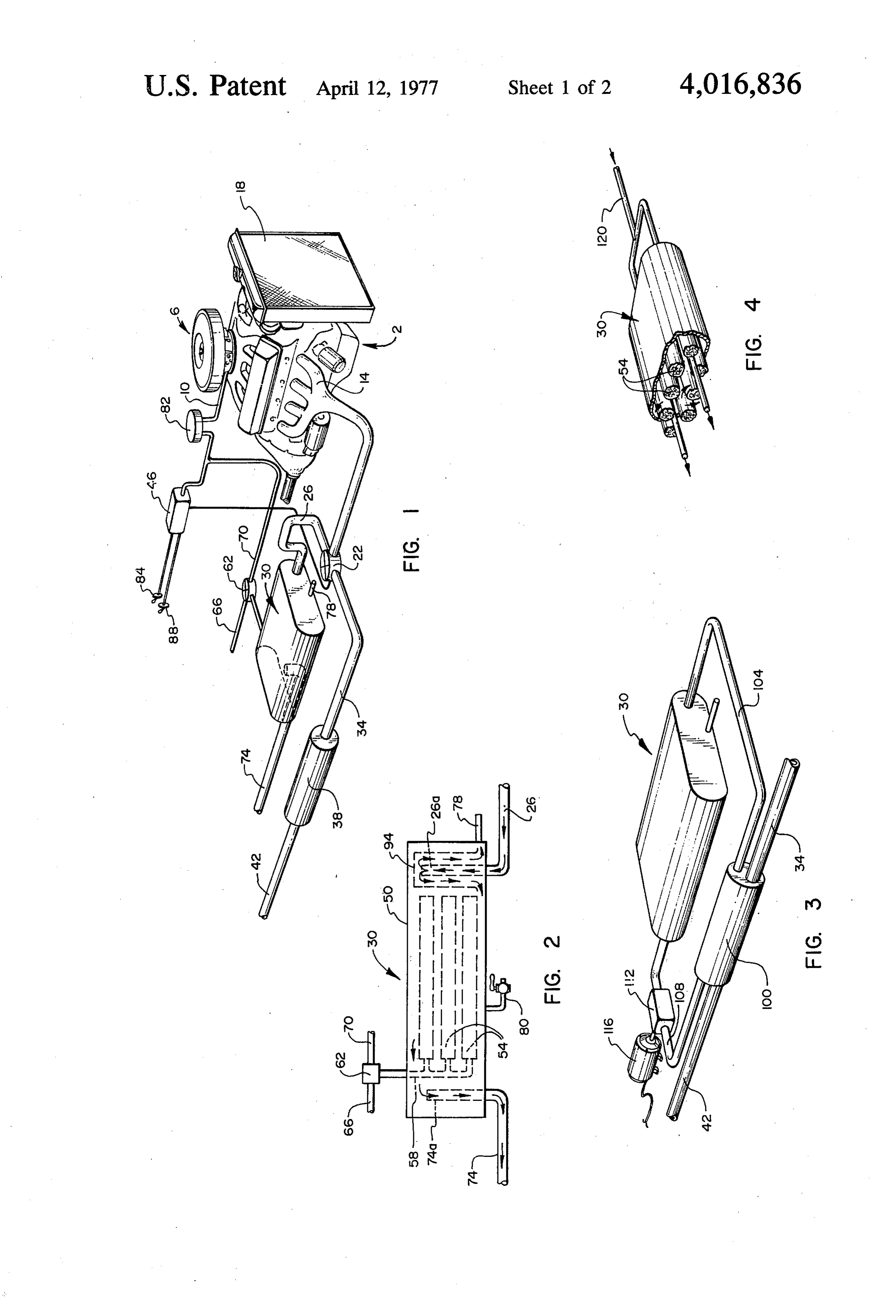
Sumer uses. BRIEF DESCRIPTION OF THE DRAWINGS The use of hydride material (hereinafter defined to The above and other objects, features and advan mean any metals, metal compounds or other materials tages capable of absorbing and holding hydrogen) appears to from of the present invention can best be understood the following detailed description presented in be an attractive approach to the storage of hydrogen connection with the accompanying drawings in which: for consumer purposes. Exemplary hydride material 45 FIG. 1 shows one illustrative embodiment of a hy includes iron titanium, misch-metal tetranickel, and dride fuel system made in accordance with the princi columbium. Storage of hydrogen in the hydride mate ples of the present invention for use with an internal rial (sometimes referred to as hydriding the material) combustion engine;
typically involves lowering the temperature of the hy 50 FIG. 2 shows a side elevational view of an embodi dride material and then applying hydrogen gas under ment of a hydride storage tank suitable for use in the pressure to the material. After the hydride material hydride fuel system of FIG. 1;
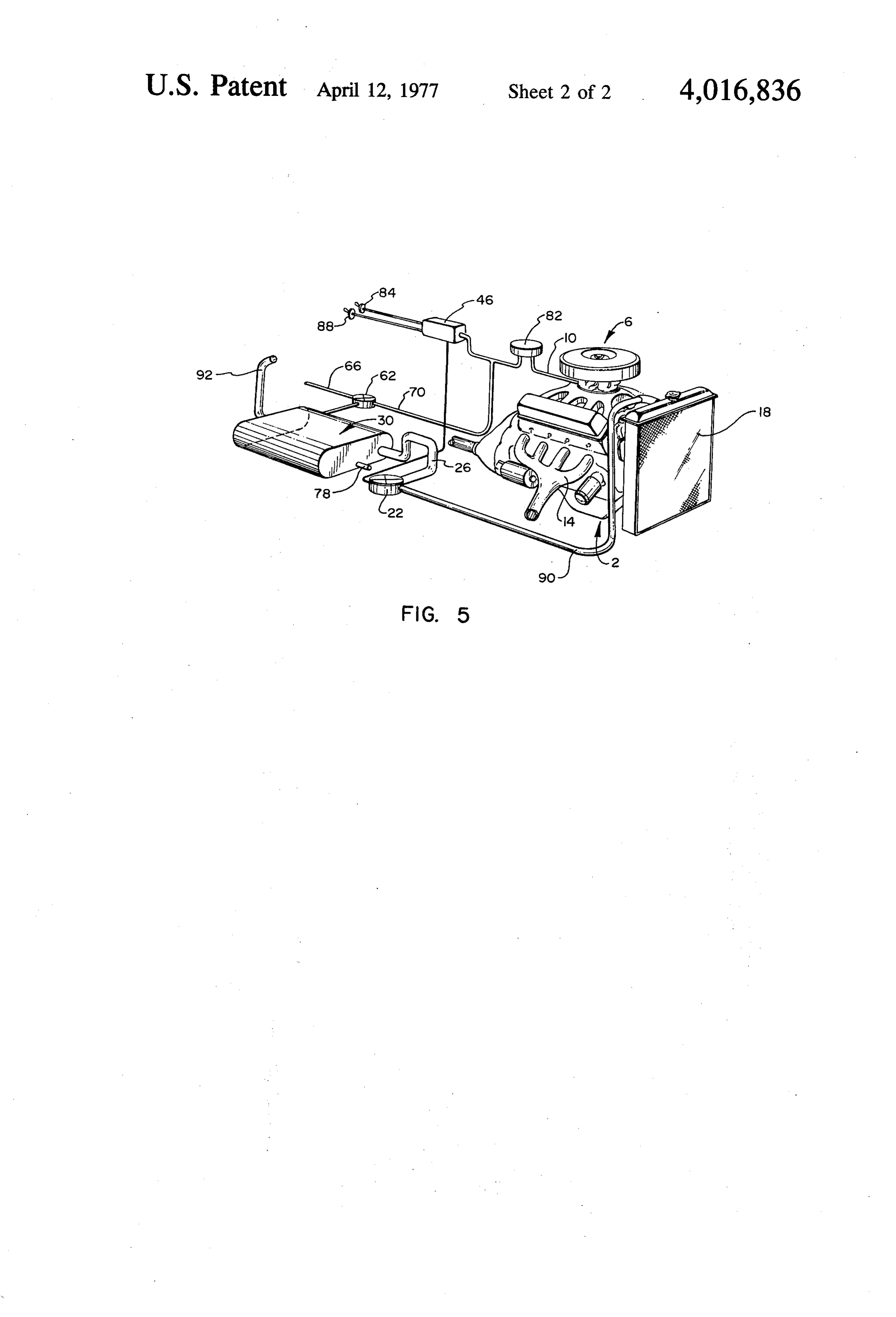
absorbs the hydrogen, the material is sealed in a con FIG. 3 shows an alternative embodiment of a hydride tainer under pressure to maintain the material in the fuel system made in accordance with the principles of hydrided state until the hydrogen is needed at a subse 55 the present invention; and quent time. Recovery or withdrawal of the hydrogen FIG. 4 shows a partially cut away view of still another involves a process substantially opposite that used for embodiment of a hydride system made in accordance storing the hydrogen, i.e., heating the hydride material with the principles of the present invention. and releasing some of the pressure of the container in FIG. 5 shows a further embodiment of a hydride which the hydride material is maintained. 60 system made in accordance with the principles of the The use of hydride material for storage of hydrogen present invention.
would appear to be especially attractive for motor vehi DETAILED DESCRIPTION cles since weight and space conservation are important considerations in motor vehicle design. A motor vehi inventionThe hydride fuel system and method of the present cle fuel system utilizing hydride material would be even 65 can be utilized with a variety of systems and more attractive if conventional motor vehicle combus apparatus which employ combustion units such as com tion engines and the accessory systems therefor can be bustion engine powered electrical generators, fuel readily adapted for use with the hydride material. cells, internal combustion engine powered motor vehi 5 cles, etc. For purposes of illustrating the invention, 74 into the hydride storage tank 30, as shown in FIG. 2, however, the invention will be described as it might be will be discussed later.
utilized with a motor vehicle powered by an internal Also included in the hydride storage tank 30 is an combustion engine. inlet 78 through which a hydride coolant is introduced In FIG. 1, there is shown a conventional internal to circulate about the containers 54 and thereby facili combustion engine 2 used to power motor vehicles. tate cooling of the hydride material to enable absorp Included on the engine is a carburetor 6 adapted to tion of hydrogen introduced through inlet pipe 66 to receive hydrogen gas through a fuel line 10 and to mix manifold 58. Such hydride coolant may, for example, the hydrogen gas with air for introduction into the be cold water. The hydride coolant is discharged engine. Exemplary carburetors suitable for use with the 10 through pipe 74 and also through a tap 80 located in engine 2 are disclosed in copending patent application, the bottom wall of the housing 50. Ser. No. 554,533. Of course, carburetors capable of Referring again to FIG. 1, the fuel line section 70 is mixing hydrogen gas and air for use with standard inter coupled both to the valve control unit 46 and to a nal combustion engines are well known. Also included pressure regulator 82 the latter of which, in turn, is with the engine 2 is an exhaust manifold 14 for receiv 15 coupled to fuel line 10. Hydrogen gas from the contain ing and carrying away exhaust gases from the combus ers inside the housing of the hydride storage tank 30 tion chambers of the engine. A radiator 18 is mounted flows through the valve 62, fuel line section 70 and in standard fashion near the front of the engine 2 for regulator 82 to the carburetor 6 of the engine. The cooling an engine coolant. pressure regulator 82 maintains a substantially constant The exhaust manifold 14 is coupled by way of a bi 20 pressure in the hydrogen gas leaving the regulator and directional valve 22 to a pipe 26 leading to a hydride thus facilitates a smooth flow of the hydrogen gas. Such storage tank 30, and to an exhaust pipe 34 leading to a pressure may, for example, be from about 20 p.s.i. to muffler 38 and another section of pipe 42. The valve 22 60 p.s. i. for a one-half inch diameter fuel line. Pressure is adapted to direct exhaust gases from the manifold 14 regulators for controlling fluid pressure are well either through the pipe 26 to the hydride storage tank 25 known.
30 or to the pipe 34 for discharge into the atmosphere, The valve control unit 46 is coupled to the fuel line or to both. In other words, as will be discussed momen section 70 for determining the pressure of the hydrogen tarily, the valve 22 may be adapted to direct all the gas entering the regulator. The valve control unit 46 is exhaust gases either through pipe 26 to the hydride also coupled to the valve 22 to control the operation of storage tank 30 or through pipe 34, muffler 38 into 30 the valve in accordance with the pressure of the hydro pipe 42 to the atmosphere. Alternatively, the valve 22 gen gas. For example, the valve control unit 46 may be may be adapted to direct a determinable portion of the adapted to cause the valve 22 to direct exhaust gases exhaust gases to pipe 26 and another portion to pipe from the manifold 14 to the pipe 34 and to prevent 34. The valve 22 may be of any standard type valve exhaust gases from entering pipe 26 and flowing to the capable of receiving fluid from one line and directing 35 hydride storage tank 30 when the pressure of the hy the fluid to either of two outlet lines or to both outlet drogen gas exceeds some predetermined value. The lines in given proportions. Advantageously, the valve level selected for causing the valve control unit 46 to 22 is a solenoid valve controlled by a valve control unit carry out this function would be determined by the 46 to be discussed later. power demands of the engine, the ability of the hydride The hydride storage tank 30 is adapted to hold hy 40 storage tank 30 to provide for the transfer of heat from dride material therein and to enable the circulation of the exhaust gases to the hydride material, and the struc a heat exchange medium in proximity with the hydride tural ability of the containers 54 (FIG. 2) to withstand material to heat the material and cause it to release hydrogen gas. Exemplary hydride storage tank configu the pressure of the hydrogen gas being released by the rations are disclosed in copending patent application, 45 within safematerial.
hydride limits,
Of course, when the pressure is then exhaust gases from the manifold
Ser. No. 570,268. FIG. 2 similarly shows an exemplary 14 can safely be introduced into the hydride storage structure for the hydride storage tank 30 of FIG. 1, this structure including a housing 50 in which are disposed tank 30 to heat the hydride material and cause release of more hydrogen gas. (The spent exhaust gases are a plurality of containers 54 (shown by dotted line). discharged through discharge pipe 74 into the atmo Containers 54 are for holding hydride material and are 50 sphere). When a sufficient reserve of hydrogen gas has spaced apart within the housing 50 to facilitate the flow been released to accommodate the operating require thereabout of fluid heat exchange medium such as ments of the engine 2 and the pressure of the hydrogen exhaust gases, engine coolant, etc. Coupled to the ends gas has built up to the predetermined level, then it is of the containers 54 is a manifold 58 for introducing desirable to inhibit further heating of the hydride mate hydrogen gas into the containers and for receiving 55 rial by the exhaust gases and therefore the exhaust hydrogen gas therefrom. The manifold 58 is coupled to gases are directed by the valve control unit 46 and a valve 62 for enabling communication between the valve 22 to the pipe 34, muffler 38 and pipe 42 into the manifold and either inlet pipe 66 or engine fuel line atmosphere.
section 70.
An alternative arrangement to that disclosed above
Heat exchange medium is introduced into the hous 60 for the control of the valve 22 is a type of proportional ing 50 of the hydride storage tank by way of the pipe 26 control in which the valve control unit 46 operates the coupled either into the bottom of the housing 50 (as valve 22 to direct a portion of the exhaust gases into shown in FIG. 2), the end of the housing 50 (as shown pipe 26 and thus into the hydride storage tank 30 and in FIG. 1), or into the housing at any other suitable a portion to the pipe 34. The amount of the portion place. Heat exchange medium is discharged from the 65 allowed to flow to the hydride storage tank 30 is in housing 50 by way of a pipe 74 coupled to the housing versely proportional to the pressure of the hydrogen at the end or side opposite that in which the pipe 26 is gas entering the regulator 82. Thus when the pressure coupled. The specific manner of coupling pipes 26 and increases, the amount of exhaust gas allowed to enter 6 the hydride storage tank 30 would be decreased to hydrogen to which it is being exposed. When the hy reduce the heating of the hydride material and genera dride material has absorbed a sufficient amount of tion of further hydrogen gas. On the other hand, when hydrogen, the valve 62 is operated to prevent introduc the hydrogen gas pressure decreased, the valve 22 tion of anymore hydrogen gas into the containers, the would be operated to direct more exhaust gases to the inlet 78 is stopped, and tap 80 (FIG. 2) is opened to hydride storage tank 30 to thereby cause further heat allow the discharge of any hydride coolant remaining in ing of the hydride material in the containers 54 (FIG. the housing of the hydride storage tank 30. With the 2) and thus increase the rate of release of hydrogen gas hydride storage tank 30 charged with hydrogen, the by the hydride material. engine 2 is ready to operate. The valve control unit 46 may be adapted to either 10 It should be mentioned at this point that charging the operate manually or automatically. Advantageously, hydride tank 30 with hydrogen could be carried out by when a switch 84 is operated to a first position, the simply applying hydrogen gas to the containers 54 with valve control unit 46 is conditioned to operate the out the use of a hydride coolant, but that such charging valve 22 in response to pressure determination of the would typically require considerably more time than if hydrogen gas as already discussed. When the switch 84 15 hydride coolant were used.
is operated to a second position, the valve control unit To start the engine 2, valve 62 is operated to allow 46 is conditioned to respond to the position of a second hydrogen gas to flow from the manifold 58 to the fuel switch 88 which, when placed in a first position, causes line section 70 and thus to the pressure regulator 82 the valve control unit 46 to direct gases from the mani and carburetor 6. The engine is started in the same fold 14 exclusively to pipe 26 and thus to the hydride 20 manner as a standard gasoline engine except that a storage tank 30. Alternatively, when the switch 88 is mixture of hydrogen gas and air are introduced into the operated to a second position, the valve control unit 46 combustion chambers for combustion. Upon starting is conditioned to operate the valve 22 to direct gases the engine 2, of course, exhaust gases flow through the from the exhaust manifold 14 to the pipe 34 only. The manifold 14 and are directed to the pipe 26 and into Switches 84 and 88 would advantageously be posi 25 the hydride storage tank to cause the hydride material tioned on the dashboard of the motor vehicle in which to release hydrogen gas and maintain the pressure of the hydride fuel system and engine are installed. This the hydrogen gas at the desired level. As already dis would enable the operator of the vehicle to select ei cussed, if the pressure exceeds some predetermined ther the automatic or manual mode of operation of the level, the valve control unit 46 causes the valve 22 to valve control unit 46 by operating switches 84 and 88 30 direct the exhaust gases to the pipe 34 for discharge located at the fingertips of the vehicle operator. into the atmosphere. In the manner described, the nor The valve control unit 46 might illustratively include mal by-products of an internal combustion engine are a pressure sensing element, such as a piezo-electric used to release the hydrogen gas which is used to power crystal, located at the inlet of the fuel line section 70 the engine.
into the unit 46 and therefore subject to pressure of 35 Although the discussion above has been directed to hydrogen gas in the section 70. The pressure sensing utilization of exhaust gases to heat the hydride mate element produces a signal which specifies the pressure rial, it should be understood that engine coolant used to level of the hydrogen gas. A threshold switch or pro cool the engine could similarly be used. Thus referring portional switch would then respond to this signal by to FIG. 5, a conduit 90 is coupled into the cooling controlling the state of the valve 22. 40 system of the engine 2 to direct engine coolant to the As indicated above, an important feature of the pre valve 22 in place of the exhaust gases. Advantageously, sent invention is the control of pressure of hydrogen the engine coolant would be withdrawn from the en gas in the containers 54 to maintain the pressure at a gine cooling system after circulation through the en level sufficient to meet the operating requirements of gine and before reintroduction of the coolant into the the engine 2, but yet not so high as to damage the 45 radiator 18, so that the coolant would be at its highest containers. This is accomplished in the FIG. embodi temperature. Then, after the engine coolant circulated ment by the valve 22 and valve control unit 46. An in the hydride storage tank 30, it would be returned via alternative arrangement would be to determine by ex a pipe 92 to the radiator 18 for circulation through the perimentation the sizes of pipe 26 and pipe 34 which radiator and then again through the engine 2. The valve would provide a suitable flow of exhaust gases to the 50 22 would control the rate of flow of engine coolant to hydride tank 30 to maintain the pressure of hydrogen the tank 30. Because, upon initially starting an engine, gas in containers 54 within a desired range for the engine coolant is not at a high temperature, some time engine in question, and then simply install a hydride would elapse before the engine coolant could function fuel system having these size pipes in motor vehicles to heat the hydride material to cause the hydride mate using such engines. Then, the valve 22 and valve con 55 rial to release hydrogen gas. However, as long as a trol unit 46 could be dispensed with, but at the expense sufficient hydrogen gas pressure were maintained in the of the more precise control afforded by including these containers 54 (FIG. 2) from the previous operation of elements. the vehicle, this time lapse should not be a problem. A brief description of the operation of the hydride Referring again to FIG. 1, it is desired that hydride fuel system of FIG. 1 will now be given. Initially, a 60 thecoolant not “back up' into the pipe 26 and thus into hydrogen gas source is coupled to inlet pipe 66, and the whileexhaust manifold 14 (or engine cooling system) the hydride storage tank 30 is being charged with valve 62 is operated to direct the gas into the contain hydrogen. To obviate this possibility, the pipe 26 is ers 54 in the hydride storage tank 30. During introduc tion of the hydrogen gas into the containers, a hydride . formed into a "gooseneck' in which a portion of the coolant is introduced via an inlet 78 to circulate about 65 pipe is elevated above the hydride storage tank 30 and the containers 54 (FIG. 2) and then out the discharge thus above the highest level to which the hydride cool pipe 74. The hydride coolant cools the hydride material ant could rise in the storage tank 30. An alternative to in the containers causing the hydride material to absorb the gooseneck arrangement is shown in FIG. 2 to in 7 clude positioning the end 26a of pipe 26 in the hydride heat exchange medium contained in the housing of the storage tank 30 at a level above the position of the end hydride storage tank 30 cause the heat exchange me 74a of the discharge pipe 74. Thus, hydride coolant dium to circulate about the containers 54 and thereby introduced via inlet 78 would flow out the discharge heat the hydride material held therein. This, again, is a pipe 74 before it reached a level where it could flow type of indirect heating which provides some of the into the end 26a of the pipe 26. advantages of the arrangement of FIG. 3 but does not In order to facilitate greater circulation of whatever include the disadvantages of having to provide the heat heat exchange medium in introduced into the hydride exchanger 100, pump 112 and motor 116. Of course, storage tank 30, a structure 94 in the form of an in valve apparatus may be included in conduits 120 to verted bucket or beaker is positioned over the end 26a 10 control the amount of heat exchange medium flowing of the pipe 26 to direct heat exchange medium flowing therethrough in response to a valve control unit such as through the pipe 26 downwardly from the end 26a to that described in FIG. 1. Also, the heat exchange me the bottom of the housing 50 prior to beginning circula dium flowing through conduits 120 could be dis tion about the containers 54. In other words, the heat charged into the atmosphere (if exhaust gases) or re exchange medium is effectively introduced into the 15 turned to its source (if engine coolant). hydride storage tank 30 near the bottom of the housing It is to be understood that the above-described em 50 to then flow upwardly to the end 74a of the dis bodiments are only illustrative of the principles of the charge pipe 74. The heat exchange medium thus must present invention. Other embodiments may be de flow not only from one end or side of the housing 50 to scribed by those skilled in the art without departing the other end or side but it also must flow from the 20 from the spirit and scope of the invention, and the bottom of the housing to near the top of the housing. appended claims are intended to cover such embodi With this configuration, a greater circulation of heat ments.
exchange medium about the containers 54 is achieved. What is claimed is:
FIG. 3 shows an alternative arrangement for heating 1. A hydride fuel system for supplying hydrogen gas the hydride material in the containers 54 in which a 25 to a combustion unit which includes a mixing unit for type of indirect heating is achieved. In this embodi mixing hydrogen gas with air for introduction into the ment, exhaust gases are not applied directly to the combustion unit, and an exhaust manifold for carrying hydride storage tank 30 but rather are applied to a heat exhaust gases from the combustion unit, said system exchanger 100 to heat another exchange medium comprising which flows through a conduit 104 to the hydride stor 30 a hydride storage tank which includes a housing and age tank 30 and then through another conduit 108 at least one container disposed in the housing for back to the heat exchanger 100. A pump 112 is dis holding hydride material, said container being dis posed in the conduit 108 to pump the heat exchange posed to enable the flow thereabout of fluid intro medium and cause it to circulate through the conduits duced into the tank, 108 and 104. The pump 112 is operated by a motor 116 35 means for delivering exhaust gases from the manifold whose power source is not shown. In operation, exhaust into the hydride storage tank to thereby heat hy gases flow through the heat exchanger 100 to heat the dride material in the container and cause the hy heat exchange medium which is pumped through the dride material to release hydrogen gas, heat exchanger and through conduit 104 into the hy an exhaust system for carrying exhaust gases from the dride storage tank 30 where it circulates about the 40 manifold into the atmosphere, containers 54 (FIG. 2). The heat exchange medium means for controlling the pressure of the hydrogen then flows out of the hydride storage tank 30 through gas in said container, the conduit 108 and pump 112 back to the heat ex means for conveying hydrogen gas from the con changer 100 where it is again heated. Advantageously, tainer to the mixing unit, a control unit similar to the valve control unit 46 of 45 means for introducing hydrogen gas into the con FIG. 1 could be employed to control operation of the tainer, and motor 116, i.e., to turn off the motor if the pressure of means for discharging exhaust gases from the hydride the hydrogen gas in the containers 54 (FIG. 2) ex storage tank.
ceeded a predetermined level so that circulation of the 2. A hydride fuel system as in claim 1 wherein said heat exchange medium through the heat exchanger 100 pressure controlling means includes means coupled is terminated and the release of hydrogen gas by the into said exhaust system for controlling the flow of hydride material in the containers is inhibited. With exhaust gases to the hydride storage tank to thereby this arrangement, the material from which the contain control the amount of hydrogen gas released from the ers 54 are constructed need be less resistant to high hydride material and thus the pressure of hydrogen gas temperatures since the containers are not subjected 55 in the container.
directly to the very hot exhaust gases. Thus, the cost of 3. A hydride fuel system as in claim 2 wherein said construction and the weight of the hydride storage tank flow controlling means includes valve means for selec 30 may be reduced. tively directing exhaust gases either to the hydride FIG. 4 shows still another embodiment of a hydride storage tank, to the atmosphere, or to both. storage tank 30 for use in the hydride fuel system of the 60 4. A hydride fuel system as in claim 3 wherein said present invention. In this embodiment, exhaust gases, hydrogen gas conveying means includes regulator or other heat exchange medium, is directed through means through which hydrogen gas flows for maintain conduits 120 which extend into and through the hous ing hydrogen gas leaving the regulator means at a sub ing of the hydride storage tank 30. Another heat ex stantially constant pressure.
change medium is maintained within the housing of the 65 5. A hydride fuel system as in claim 4 further com hydride storage tank 30 and this medium is heated by prising valve control means coupled to said hydrogen exhaust gases flowing through the conduits 120. Natu gas conveying means for operating said valve means to ral convection currents created by the heating of the direct exhaust gases to said hydride storage tank when 8 the pressure of hydrogen gas entering the regulator inlet means in the housing of the storage tank means through the conveying means is below some through which a third heat exchange medium may predetermined level. be introduced into the tank to cool the hydride 6. A hydride fuel system as in claim 4 further com material in the containers and thereby cause the prising valve control means coupled to said hydrogen 5 hydride material to absorb hydrogen to which the gas conveying means for operating said valve means to hydride material is exposed, and direct a portion of the exhaust gases to said hydride outlet means in said housing for discharging heat tank, wherein such portion is inversely proportional to exchange medium from the storage tank, the pressure of hydrogen gas entering the regulator 14. A hydride fuel system as in claim 13 wherein said means through the conveying means. 10 hydrogen gas conveying means includes a pressure 7. A hydride fuel system as in claim 3 further com mixing regulator through which the hydrogen gas flows to the prising pressure detection means for determining the the regulator unit for maintaining the hydrogen gas leaving pressure of the hydrogen gas in said container and for at a substantially constant pressure. 15. A hydride fuel system as in claim 14 wherein said operating said valve means to direct exhaust gases to 15 determining said hydride storage tank when the pressure of hydro means is a valve. gen gas in the container is below some predetermined prising 16. A hydride fuel system as in claim 15 further com level. pressure determining means coupled to said containers 8. A hydride fuel system as in claim 2 further com gas in the containersfor determining the pressure of hydrogen prising inlet means in the housing of the hydride stor 20 direct a portion of theand for operating said valve to second heat exchange medium age tank through which coolant may be introduced into through said second heat exchange medium carrying the tank to thereby cool hydride material in the con means, wherein such portion is inversely proportional tainer and cause the hydride material to absorb hydro to the pressure of the hydrogen gas detected by the gen to which the hydride material is exposed. pressure determining means. 9. A hydride fuel system as in claim 8 wherein at least 17. A hydride fuel system as in claim 13 wherein the a portion of said exhaust gas delivering means through 25 combustion unit includes an exhaust manifold for car which exhaust gases travel is elevated above the level to rying exhaust gases from the combustion unit, and which coolant in the hydride storage tank may rise. wherein said second heat exchange medium carrying 10. A hydride fuel system as in claim 9 wherein said means is coupled to the manifold for carrying exhaust exhaust gas delivering means is adapted to deliver ex 30 gases from the manifold through the storage tank. haust gases into said hydride storage tank near the 18. A hydride fuel system as in claim 13 wherein the bottom and one side thereof, wherein said discharging combustion unit includes a cooling system for circulat means is adapted to receive exhaust gases and coolant ing through the combustion unit, and wherein said from the hydride storage tank near the top and an second heat exchange medium carrying means is cou opposite side thereof, and wherein at least a portion of 35 pled into the cooling system for carrying coolant from said container is disposed between said exhaust gas the cooling system through the storage tank. delivering means and said discharging means. 19. A hydride fuel system for supplying hydrogen gas 11. A hydride fuel system as in claim 10 wherein said to a combustion unit having a mixture unit for mixing hydride storage tank includes tap means located in a hydrogen gas with air for introduction into the combus bottom wall of the tank through which coolant may be 40 tion unit, and an exhaust system for carrying exhaust withdrawn from the tank. gases from the combustion unit, said hydride fuel sys 12. A hydride fuel system for supplying hydrogen gas tem comprising to a combustion unit which includes a mixing unit for a hydride storage tank which includes a housing and mixing hydrogen gas with air for introduction into the a plurality of containers disposed in the housing for combustion unit, said system comprising 45 holding hydride material, said containers being a storage tank which includes a housing for holding a spaced apart to enable the flow thereabout of fluid first heat exchange medium, and a plurality of con introduced into the tank, tainers disposed in the housing for holding hydride heat exchanger means coupled into the exhaust sys material, said containers being spaced apart to tem for heating a heat exchange medium, enable the flow thereabout of heat exchange me 50 means for carrying heat exhaust medium from the dium contained in the housing, heat exchanger means to the hydride storage tank means extending through said storage tank among and from the hydride storage tank back to the heat said containers for carrying a second heat ex exchanger means, change medium through the storage tank to pump means coupled into said heat exchange me thereby heat the first heat exchange medium, and 55 dium carrying means for causing the heat exchange thus cause the first heat exchange medium to heat medium to circulate through the carrying means, hydride material in the containers and cause the means for conveying hydrogen gas from the contain hydride material to release hydrogen gas, ers to the mixing unit, and means coupled into said second heat exchange me means for introducing hydrogen gas into the contain dium carrying means for determining the flow of 60 e.S.
the second heat exchange medium through the 20. A hydride fuel system as in claim 19 further com carrying means, prising inlet means in the housing of the hydride stor means for conveying hydrogen gas from the contain age tank through which coolant may be introduced into ers to the mixing unit, and the tank to thereby cool the hydride material in the means for introducing hydrogen gas into the contain 65 containers and cause the hydride material to absorb es. hydrogen introduced into the containers. 13. A hydride fuel system as in claim 12 further com 21. A hydride fuel system as in claim 20 further com prising prising a regulator means disposed in said hydrogen gas 9 conveying means for maintaining the pressure of the the first coolant to the hydride storage tank as the hydrogen gas entering the mixing unit at a substantially pressure of hydrogen gas entering the regulator constant pressure. means through the conveying means increases. 22. A hydride fuel system as in claim 21 further com 27. A method of supplying hydrogen gas to a com prising pressure determining means coupled to said 5 bustion unit which includes a mixing unit for mixing containers for determining the pressure of hydrogen hydrogen gas with air for introduction into the combus gas in the containers and for inhibiting the operation of tion unit, said method including said pump means when the pressure of hydrogen gas in a. conveying to the mixing unit hydrogen gas from at said containers exceeds some predetermined level. least one container disposed in a hydride storage 23. A hydride fuel system for supplying hydrogen gas 10 tank, said container adapted to hold hydride mate to a combustion unit having a mixing unit for mixing rial and said hydride storage tank having a housing hydrogen gas with air for introduction into the combus in which the container is disposed so as to allow tion unit, and a cooling system for circulating a first fluid to flow about the container, coolant through the combustion unit, said system com b. introducing hydrogen gas into the container, prising 15 c. introducing exhaust gases from the combustion a hydride storage tank which includes a housing for unit into the hydride storage tank to circulate holding a hydride material, said container being about the container and thereby heat the hydride disposed to enable the flow thereabout of fluid material held in the container to cause the material introduced into the tank, - to release hydrogen gas, means for delivering the coolant from the cooling 20 d. container controlling the pressure of the hydrogen gas in the to maintain the pressure below a prede system to the hydride storage tank and from the storage tank back to the cooling system, to thereby termined level, and heat hydride material in the container and cause e. discharging exhaust gases from the hydride storage tank.
the hydride material to release hydrogen gas, 28. A method as in claim 27 wherein step (d) com means for conveying hydrogen gas from the con 25 prises inhibiting step (c) when the pressure of the hy tainer to the mixing unit, means for introducing hydrogen gas into the con level. gas in the container exceeds a predetermined drogen tainer.
24. A hydride fuel system as in claim 23 further com 30 f.29.introducing
A method as in claim 27 further including a heat exchange medium into the hy prising inlet means in the housing of the hydride stor dride storage tank to circulate about the container age tank through which a hydride coolant may be intro and thereby cool hydride material in the container duced into the tank to thereby cool hydride material in to cause the hydride material to absorb hydrogen the container and cause the hydride material to absorb hydrogen to which the hydride material is exposed. 35 g. introduced withdrawing into the container, and the heat exchange medium from the 25. A hydride system as in claim 24 wherein said hydride storage tank.
hydrogen gas conveying means includes regulator 30. A method as in claim 29 wherein step (c) com means through which hydrogen gas flows for maintain prises introducing exhaust gases from the combustion ing hydrogen gas leaving the regulator at a substantially unit into the hydride storage tank from an elevation constant pressure. above the level to which the heat exchange medium 26. A hydride system as in claim 25 further compris 40 may rise in the tank.
ling valve means coupled into said first coolant delivering (g)31.comprise
A method as in claim 30 wherein steps (e) and withdrawing exhaust gases and heat ex means for controlling the rate of flow of the first change medium from the hydride storage tank near the coolant to the hydride storage tank, and top and one side thereof, and wherein step (c) further valve control means coupled to said hydrogen gas 45 comprises introducing exhaust gases into the tank near conveying means and to said valve means for caus the bottom and an opposite side thereof. ing the valve means to reduce the rate of flow of ck k . . k. k.
Provenance
- Collection
- Patents citing this work
- Pages
- 9
- Method
- pdftotext (the PDF's own text layer) + pdftoppm 300dpi page scans
- Patent office record
- patents.google.com →
- Source
- Google Patents citing-documents table
- Assignee
- Billings Energy Research Corporation
- Published
- 1977-04-12
- Transcribed from
- patentimages.storage.googleapis.com →