

patent · US4019853A
Automatic fuel ignition apparatus
26 April 1977
Text
Page 1scan →
Sears et al.
54 automatic fuel ignition apparatus
(75) Inventors: Arthur H. Sears, Youngstown;
August J. Siuta, Jr., Lockport, both (73) Assignee: The Carborundum Company,
Niagara Falls, N.Y.
& - P-AK - 8 - - -- - - - - - - - - 416,1 s76 58) Field of search 40 - 0 8 - - - - - - - - - - - - - - - - -431767, 73, 77, 78:
United states patents
2,542,666 2/1951 Hall ................................. 431178 X
3,153,440 10, 1964 Baumanns a a a a - a - - - - - - - - - - - a 431/67 3,778,218 12/1973 Wright etal. ......................... 431/67 Primary Examiner-Edgar W. Geoghegan
Attorney, Agent, or Firm-David E. Dougherty;
Raymond W. Green; Michael L. Dunn
An apparatus for fluid fuel ignition which consists es sentially of an igniter which reaches a temperature above the ignition temperature of the fuel when suffi cient electricity from an electrical source passes through the igniter and which igniter remains continu ously at a temperature above the ignition temperature of the fuel while the fuel passes through a fuel injection means proximate to the igniter. A thermal delay relay which activates a valve, which permits fuel to pass through the fuel injection means proximate the igniter, is responsive to current flow through the igniter after the igniter has reached ignition temperature. The appa ratus requires no mechanical moving parts other than a thermostat, one electrical relay and a fuel valve respon sive to an electrical signal. Only two sets of electrical contacts are required in the entire apparatus including the thermostat and internal relay contacts. The appara tus may be conveniently designed to operate at either low or high voltage. A low voltage thermostatic control may optionally be used in conjunction with a high volt age ignition which requires only one additional relay.
16 Claims, 3 Drawing Figures
Drawings
Page 2drawing sheetscan →
Page 3scan →
connected to the electrical source in series with the
AUTOMATC FUEL GNTON APPARATUS igniter and time delay relay. The primary control means causes an electrical current from the electrical
BACKGROUND OF THE INVENTION source to flow through the igniter and time delay relay This invention concerns a fuel ignition apparatus 5 when the contacts in the primary control means are which safely controls the passage of fuel to a fuel ig closed. A normally closed fuel valve connected be niter. tween a fuel supply and a fuel injection means is also In the prior art apparatus for safely controlling the provided. The valve is electrically connected in series flow of fuel to an igniter were known; however, prior with the contacts in the time delay relay to the electri art apparatus had serious disadvantages. The first such 10 cal source and is electrically activated to its open posi apparatus were not electrically controlled but were tion when the contacts in the time delay relay are devices subject to mechanical failure. The first such closed. The fuel injection means is positioned to permit apparatus employing electric igniters were designed to fuel passing through the fuel injection means from the permit the current to stop flowing through the igniter fuel supply to pass close enough to the igniter to cause after commencement of combustion of the fuel. In such 15 the fuel to ignite.
apparatus, means for stopping flow of current through Should the igniter cease to function, which can only the electrical igniters were necessary to prevent the happen if current ceases to flow through the igniter igniter from rapidly burning out. In addition, complex circuit, i.e., by failure of the electrical source or by a apparatus was required to shut off the flow of fuel from gap in the igniter such as would be caused by igniter a fuel source in the event that combustion accidentally 20 burnout, the time delay relay would be deactivated ceased. since the activation of the time delay relay is dependent Improved electrical igniters were subsequently devel upon the flow of current through the igniter circuit. oped which permitted continuous flow of current When the time delay relay is deactivated, the contacts through the igniter during the entire period that fuel in the relay open, thus stopping the flow of electric flowed from the fuel source. Prior art apparatus em- 25 current to the fuel valve which then closes to stop the ploying such continuously operated igniters utilized flow of fuel from the fuel source. It is therefore clear complex electrical and mechanical devices to shut off that the igniter must be in operation to permit the fuel the flow of fuel in the event that the igniter ceased to to flow from the fuel source. In addition, while the function. Apparatus which does not incorporate a de igniter is in operation, combustion of fuel from the fuel vice or system for stopping flow of fuel from the fuel 30 source will not stop since the continuously operated source when the igniter ceases to function is not con igniter will cause fuel passing from the fuel source to sidered safe since in the event that combustion acci burn even after the occurrence of a temporary condi dentally ceases, unburned fuel would continue to flow tion which might otherwise stop combustion. Such a from the fuel source thus presenting an explosion and temporary condition might for example be an interrup toxicity hazard. 35 tion in fuel flow from the fuel source. The continuously SUMMARY OF THE INVENTION operated igniter will not permit the hazardous collec tion of unburned fuel since the instant that unburned
The present invention provides apparatus for auto fuel contacts the igniter, combustion of the fuel will matic fluid fuel ignition, comprising: (a) an electrical again commence.
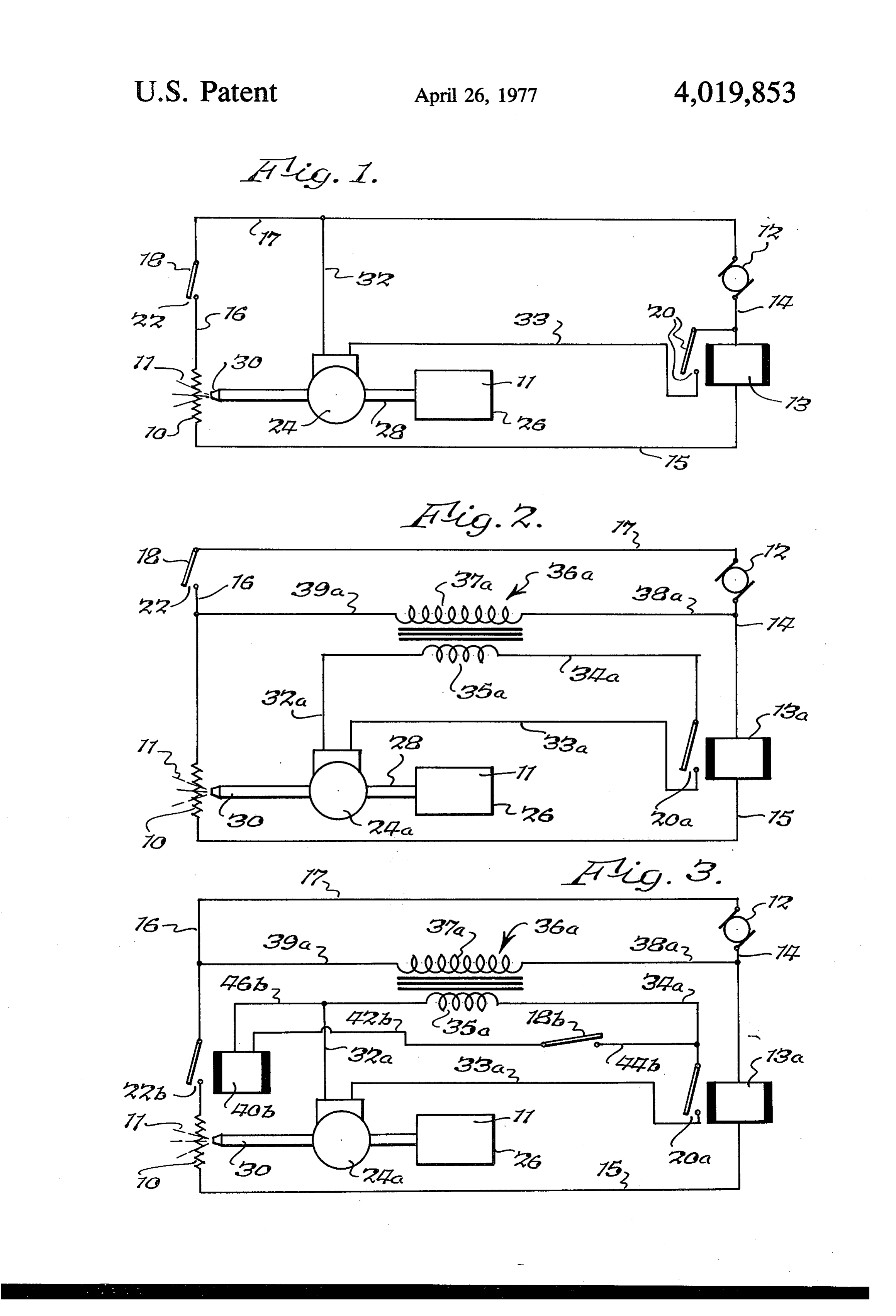
resistance igniter means for igniting fluid fuel; (b) fluid 40 BRIEF DESCRIPTION OF THE DRAWINGS fuel supply means comprising a normally closed fluid fuel valve; (c) fluid fuel flow means for flowing the fuel FIG. 1 is a schematic diagram of the apparatus of the proximate the igniter means when the fluid fuel valve is invention wherein all components of the invention open; and (d) valve opening means comprising a time operate from a single electrical source. delay relay, electrically connected in series to the ig- 45 FIG. 2 is a schematic diagram of an alternative em niter means, for opening the fluid fuel valve after the bodiment of the apparatus of the invention wherein the igniter means is at a temperature above the ignition fuel valve is operated by a low voltage electrical source temperature of the fluid fuel. and the igniter is operated by a high voltage electrical The apparatus of the present invention is simple in SOCC design, utilizes few mechanical parts, yet safely stops 50 FIG. 3 is a schematic diagram of a second alternative the flow of fuel from the fuel source in the event that embodiment of the invention wherein both the primary the igniter ceases to function. The apparatus for auto control means and fuel valve are operated by a low matic fuel ignition in accordance with the present in voltage electrical source and the igniter is operated by vention consists essentially of an igniter which reaches a high voltage electrical source. a temperature above the ignition temperature of the 55 DETAILED DESCRIPTION OF THE INVENTION fuel to be ignited when sufficient electricity from the electrical source passes through the igniter. A time The electrical source may be a high voltage electrical delay relay is provided which is connected to the elec source, i.e., between about 75 and about 600 volts, or trical source in series with the igniter. The time delay may be a low voltage electrical source, i.e., between relay contains a normally open set of electrical contacts 60 about 6 and 75 volts. In addition, the apparatus of the which are closed after a time delay when the relay is invention may operate upon a combination of both activated by an electrical current which flows from the high and low voltage electrical sources. The electrical electrical source through the relay and igniter. To acti source may be an alternating current electrical source, vate the relay the electrical current must be sufficient e.g., 60 cycles per second, or may be a direct current to heat the igniter to a temperature above the ignition 65 electrical source. When both high and low voltage temperature of the fuel. A primary control means, such electrical sources are used they may be either indepen as a thermostat, a manual switch, or relay activated dent or interdependent. For example, the high voltage switch is provided, which has a set of electrical contacts electrical source may be commercially supplied electri 4 cal power or may be a battery of a large number, i.e., cal resistance in the relay to become heated, for the over 50, of direct current cells. The low voltage electri heat to be transferred to the bimetallic strip and for the cal source may be either a low voltage direct current bimetallic strip to bend to close the contacts. In accor electrical source such as would be supplied by a battery dance with the preferred embodiment of the invention, of a smaller number of direct current cells, i.e., from the electrical resistance which heats the bimetallic strip about four to about 50 cells, or may be obtained from is connected in series: with the igniter in the igniter a transformer which steps down the voltage from the circuit and is electrically compatible with the electrical high voltage electrical source. When a combination of current flowing through the igniter circuit so that the high and low voltage electrical sources is used, in gen 10 resistance becomes sufficiently heated to cause bend eral the high voltage electrical source is used in the ing of the metallic strip, but does not become over igniter circuit and the low voltage electrical source is heated so as to cause the electrical resistance in the used to operate the remaining elements of the circuit, time delay relay to melt or burn.
that is, the primary control means and fuel valve. The primary control means having a set of electrical The electrical source which operates the apparatus contacts connected to the electrical source in series whether it is a high voltage electrical source, a low 15 primarywith the igniter and time delay relay is any suitable voltage electrical source or a combination of high and switch, a control means such as a manually operated thermostat, an automatically operated electri low voltage electrical sources, is usually an alternating current. The electrical source may, however, be a di cal switch, or a combination of these such as a manual rect current when there are no components in the ap switch plus a thermostat, as for example in a gas oven. paratus, such as a transformer, which depend upon 20 When the primary control means is an automatically electrical induction for operation. operated electrical switch, it preferably is automati The igniter, which reaches a temperature above the cally operated by an electrical current which may origi ignition temperature of the fuel when sufficient elec nate from either a high or low voltage electrical source. tricity from the electrical source passes through the When an electrical current is used to operate the pri mary control means, it may be a high voltage electrical igniter, is an electrical resistance, preferably of silicon 25. current, carbide, which converts a large portion of the electric rent thusbut is preferably a low voltage electrical cur eliminating high voltage hazards. In the pre ity passing through the resistance to heat. Furthermore, the igniter is capable of continuous operation without ferred embodiment of the invention, the primary con burning up due to its self-generated heat. The igniter trol means comprises a set of electrical contacts which and the source connected with the igniter must be 30 when are controlled by a relay coil which closes the contacts matched so that sufficient current passes through the the relay coil is activated by a low voltage electri igniter to generate a temperature above the ignition cal source. In accordance with the preferred embodi temperature of the fuel and so that insufficient current ment of the invention, a thermostat is preferably con passes through the igniter to cause the igniter to melt or nected in series with the relay coil to the low voltage burn thus creating an electrical gap in the igniter cir 35 electrical source. When the temperature surrounding cuit. Suitable igniters are known, for example, from the thermostat drops sufficiently, the thermostat U.S. Pat. No. 3,372,305 and U.S. applications Ser. Nos. contacts will close thus activating the relay coil which 435,352, filed Jan. 21, 1974 and 477,707, filed June in turn closes the electrical contacts which are in series 10, 1974 now abandoned. in the igniter circuit. When the electrical contacts in The fuel for use in conjunction with the apparatus of 40 the igniter circuit are closed, the igniter circuit is com the invention may be any suitable combustible fluid plete, thus causing the igniter, to become heated to a such as fuel oil, kerosene, alcohol, propane, butane, temperature above the ignition temperature of the fuel. coal gas, gasoline, natural gas, and acetylene. The low voltage electrical source which activates the The time delay relay connected with the electrical 45 relay coil is preferably the secondary of a step-down source in series with the igniter may be any suitable transformer having its primary connected with a high electrically activated time delay relay. In general, the voltage electrical source which is the same as the elec time delay relay preferred for use in conjunction with trical source connected with the igniter. the apparatus of the invention comprises an electrical The normally closed fuel valve connected between a resistance which becomes heated upon the passage of 50 fuel valve supply and a fuel injection means is any suitable which can be electrically activated by the electri sufficient electrical current through the electrical resis tance and a bimetallic strip which becomes heated by cal source to which it is connected. The normally the heat generated by the electrical resistance. The closed fuel valve is generally a solenoid valve which has electrical resistance of the relay does not begin to heat a solenoid coil connected to the activating electrical up substantially until the igniter is heated, however, source in series with the contacts in the time delay due to the series connection of the igniter and the relay. 55 relay. The fuel valve is electrically activated to its open The current first flows through the cold igniter and position when the contacts in the time delay relay are relay in smaller amounts, until the igniter becomes closed. The "normal' mode is when the igniter is cold heated (by the flow of current) sufficiently to lower its and fuel is not flowing.
The fuel injection means is positioned to permit fuel resistance and thereby further allow the current flow to 60 passing increase. After the igniter is thus heated and the cur enough through the fuel injection means to pass close to the igniter to cause the fuel to ignite and is rent flow raised, greater quantities of current flow through the electrical resistance of the relay, generat generally any suitable orifice in or at the end of a fuel conduit. Suitable fuel injection means include nozzles ing heat which causes the bimetallic strip to bend.
As the bimetallic strip bends, a set of electrical and fuelfuelburners having a series of orifices. contacts in the time delay relay is closed. This second 65 anyThesuitable supply which the fuel valve is connected is time delay (the first being the time necessary to build line or a fuel fuel supply and may be a commercial gas container such as a low pressure gas cylin up sufficient current in the igniter to lower its resis tance) results from the time lag required for the electri der or an oil tank.
Page 5scan →
The normally closed fuel valve can be operated by open set of electrical contacts 20 which are closed after either a high or low voltage electrical source. The fuel a time delay when relay 13 is activated by an electrical valve is however, preferably operated by a low voltage current which flows from electrical source 12 through electrical source to eliminate high voltage hazards. The relay 13 and igniter 10.
low voltage electrical source is preferably the secon The primary control means 18 has a set of electrical dary of a step-down transformer having its primary contacts 22 connected to electrical source 12 in series connected with a high voltage electrical source which is with igniter 10 and time delay relay 13 by means of the same as the electrical source connected to the ig electrical conductors 14, 15, 16 and 17. The primary inter. control means causes an electrical current from electri When the switch or electrical contacts in series with O cal source 12 to flow through the igniter 10 and time the igniter are controlled by a relay coil activated by a delay relay 13 when contacts 22 in the primary control low voltage electrical source and when the normally means 18 are closed. A normally closed fuel valve 24 is closed fuel valve is activated by a low voltage electrical connected between a fuel supply 26 by means of con source, the low voltage electrical source for both the duit 28 and a fuel injection means 30. relay coil and the normally closed fuel valve may be the 15 Fuel valve 24 is electrically connected by means of Sale. electrical conductors 14, 17, 32 and 33 to electrical In operation the set of electrical contact in the pri source 12 in series with electrical contacts 20 in time mary control means become closed either manually or delay relay 13. Fuel valve 24 is electrically activated to automatically. Since the electrical contacts of the pri an open position when contacts 20 in time delay relay mary control means are connected to an electrical 20 13 are closed. Fuel injection means 30 is positioned to source in series with the igniter and time delay relay, permit fuel 11 passing through fuel injection means 30 the closing of the primary control electrical contacts to pass close enough to igniter 10 to cause the passing causes an electrical current from the connected electri fuel to ignite. Primary control means 18 as shown in cal source to flow through the igniter and time delay FIG. 1, may be any suitable electrical switch mecha relay. The flow of the electrical current through the 25 nism such as a thermostat or a manually operated igniter soon causes the igniter to reach a temperature switch.
above the ignition temperature of the fuel and the flow In operation, electrical contacts 22 become closed of the electrical current through the time delay relay thus permitting an electrical current from electrical closes a normally open set of electrical contacts in the source 12 to flow through igniter 10, time delay relay time delay relay after a time delay. 30 13 and electrical conductors 14, 15, 16 and 17. The Since the electrical contacts in the time delay relay flow of electrical current through igniter 10 soon are connected to an electrical source in series with an causes igniter 10 to reach a temperature above the activating coil in a normally closed fuel valve, the clos ignition temperature of fuel 11.
ing of the contacts in the time delay relay results in the The flow of electrical current through time delay flow of an electrical current from an electrical source 35 relay 13 causes electrical contacts 20 to become closed through the activating coil in the normally closed fuel after a time delay. When electrical contacts 20 become valve thus opening the fuel valve to permit fuel to flow closed, fuel valve 24 which is electrically connected by proximate the igniter. The heat of the igniter then means of electrical conductors 14, 17, 32 and 33, to causes the fuel to ignite. electrical source 12 in series with electrical contacts If at any time the flow of fuel to the igniter becomes 40 20, becomes electrically activated to an open position interrupted, thus causing combustion to cease, the thus causing fuel 11 to flow from fuel supply 26 igniter will stay heated and will re-ignite the fuel when through valve 24 through fuel injection means 30 to fuel flow again commences. The continuously operat igniter 10 which causes fuel 11 to ignite. The flow of ing igniter therefore prevents the hazardous collection electrical current through igniter 10 is continuous thus of unburned fuel. 45 igniter 10 is continuously at a temperature above the If at any time, for any reason, the igniter circuit fails, ignition temperature of fuel 11. An interruption in the for example by burnout of the igniter, the time delay flow of fuel 11 to igniter 10 will stop ignition. However, relay will become rapidly deactivated, due to the dis the hazardous collection of fuel 11 will not be permit continuance of flow of electricity through the relay, ted since when the flow of fuel again resumes, igniter thus in turn deactivating the fuel valve which will re 50 10 will re-ignite the fuel. If at any time the flow of turn to the closed position to cut off fuel flow. electrical current through igniter 10 stops, for example It is therefore clear that the apparatus of the inven by burnout of igniter 10, time delay relay 13 will be tion is an apparatus for automatic fuel ignition which come deactivated thus opening electrical contacts 20 overcomes the disadvantages of prior art fluid fuel which will cause fuel valve 24 to close thus shutting off ignition apparatus since the apparatus of the invention 55 theFIG. flow of fuel to fuel injection means 30. 2 shows an alternative embodiment of the in is safe, simple and reliable.
Referring now to the drawings as best seen in FIG. 1 vention which operates in essentially the same manner of the invention, in its simplest form, the automatic fuel as the embodiment shown in FIG. 1 except that fuel ignition apparatus of the invention consists essentially valve 24a operates on low rather than high voltage and of an igniter 10, which in general is an electrical resis 60 is electrically connected by means of conductors 32a, tance, which reaches a temperature above the ignition 33a and 34a to a low voltage source 35a in series with temperature of fuel 11 when sufficient electricity from contacts 20a of time delay relay 13a. electrical sources 12 passes through igniter 10. Low voltage source 35a is the secondary of step A time delay relay 13 is connected with the electrical down transformer 36a which has its primary 37a elec source 12 by means of electrical conductors 14, 15, 16 65 trically connected by means of electrical conductors and 17. The time delay relay is connected to the electri 38a, 14, 17, 16 and 39a to electrical source 12 in series cal source in series with igniter 10 and a primary con with primary control means 18 in such a way that when trol means 18. Time delay relay 13 contains a normally electrical contacts 22 in primary control means 18 are 6 closed, the primary 37a of transformer 36a is activated to activate said relay only after the igniter reaches thus activating secondary 35a of transformer 36a. a temperature above the ignition temperature of FIG. 3 shows a second alternative embodiment of the the fuel;
invention which operates in essentially the same way as c. a primary control means having a set of electrical the apparatus shown in FIG. 2 except that the primary 5 contacts connected to the electrical source in se control means comprises a set of electrical contacts ries with the igniter and time delay relay, said pri 22b which are controlled by a relay coil 40b which mary control means causing said electrical current closes contacts 22b when relay coil 40b is activated by from the electrical source to flow through the ig low voltage source 35a. Low voltage source 35a is niter and time delay relay when said contacts in the connected with relay coil 40b by means of electrical 10 primary control means are closed; and conductors 42b, 44b, 34a and 46b. A primary control d. a normally closed fuel valve connected between a switch 18b is connected in series with relay 40b to low fuel supply and a fuel injection means, said valve voltage source 35a. Primary control switch 18b may be being electrically connected to an electrical source a thermostat or a manually operated switch. in series with the contacts in the time delay relay, What is claimed is: 15 said fuel valve being electrically activated to its 1. Apparatus for automatic fluid fuel ignition, com open position when the contacts in the time delay prising: relay are closed, said fuel injection means being a. an electrical resistance igniter means for igniting positioned to permit fuel passing through said fuel fluid fuel; injection means to pass close enough to the igniter b. fluid fuel supply means including a normally closed 20 7. toThe cause said fuel to ignite. apparatus as claimed in claim 6 wherein the fluid fuel valve;
c. fluid fuel flow means for flowing the fuel proximate electrical relay are source to which the igniter and time delay connected in series is a high voltage electrical the igniter means when the fluid fuel valve is open; SOCe.
and d. valve opening means comprising an electrically 25 primary 8. The apparatus as claimed in claim 7 wherein the activated time delay relay, electrically connected control means is a thermostat. in series to the igniter means, for opening the fluid 9. The apparatus as claimed in claim 8 wherein the fuel valve, sufficient electrical current to activate electrical source connected to the valve is a low voltage electrical source.
said relay passing through said relay only after the 30 10. The apparatus as claimed in claim 8 wherein the igniter means is at a temperature above the ignition electrical source connected to the valve is a high volt temperature of the fluid fuel.
2. The apparatus as claimed in claim 1, wherein the age11.electrical
The source connected with the igniter.
apparatus as claimed in claim 9 wherein the time delay relay contains a normally open set of electri electrical source connected to the valve is the secon cal contacts which are closable after time delay, re 35 dary of a step-down transformer having its primary sponsive to electrical current passing through the relay. connected with a high voltage electrical source which is 3. The apparatus as claimed in claim 2, comprising in the same as the electrical source connected with the addition primary control means for causing electric igniter.
current to flow through the igniter means and through 12. The apparatus as claimed in claim 11 wherein the the time delay relay. 40 thermostat is connected in series with the high voltage 4. The apparatus as claimed in claim 3, wherein the electrical source and the primary of the transformer. igniter means, time delay relay and primary control 13. The apparatus as claimed in claim 7 wherein the means are electrically connected in series. electrical contacts in the primary control means are 5. The apparatus as claimed in claim 4, wherein the controlled by a relay coil which closes the contacts in igniter means, time delay relay and primary control 45 the primary control means when the relay coil is acti means are also electrically connected in series to an vated by a low voltage electrical source. electrical source. 14. The apparatus as claimed in claim 13 wherein a 6. An apparatus for automatic fuel ignition consisting thermostat is connected in series with the relay coil to essentially of the low voltage electrical source. a. an igniter which reaches a temperature above the 50 15. The apparatus as claimed in claim 14 wherein the ignition temperature of the fuel when sufficient electrical source connected to the relay coil is the sec electrical current from an electrical source passes ondary of a step-down transformer having its primary through the igniter; connected with a high voltage electrical source which is b. a time delay relay connected with the electrical the same as the electrical source connected with the source in series with the igniter, said time delay igniter.
relay containing a normally open set of electrical 55 16. The apparatus as claimed in claim 15 wherein contacts which are closed after a time delay when electrical source connected to the valve is a low voltage the relay is activated by an electrical current which electrical source and is the same low voltage electrical flows from the electrical source through the relay source which is connected to the relay coil. and igniter, said electrical current being sufficient 60 k is
Provenance
- Collection
- Patents citing this work
- Pages
- 6
- Method
- pdftotext (the PDF's own text layer) + pdftoppm 300dpi page scans
- Patent office record
- patents.google.com →
- Source
- Google Patents citing-documents table
- Assignee
- The Carborundum Company
- Published
- 1977-04-26
- Transcribed from
- patentimages.storage.googleapis.com →