

patent · US4025807A
Electromagnetic motor
24 May 1977
Text
Page 1bibliographic recordscan →
United States Patent (19) 11 4,025,807 Clover, deceased et al. (45) May 24, 1977 (54) ELECTROMAGNETIC MOTOR 3,396,296 8/1968 Esters .................................. 31.0/46 3,426,224 2/1969 Esters .................................. 310/46 (76) Inventors: San
Leonard W. Clover, deceased, late of
Jose, Calif.; by Grace Clover,
administratrix, 19759 Douglas Ave., Primary Examiner-Donovan F. Duggan
Saratoga, Calif. 95070 Attorney, Agent, or Firm-Paul B. Fihe (22 Filed: Jan. 26, 1976 57 ABSTRACT (21) Appl. No.: 652,498 An electromagnetic motor including a rotor having a U.S. C. ................................................. 31046 plurality of permanent magnets on its periphery and a (51) Int. Cl”........................................ H02K 37/00 stator closely encompassing the rotor and having a Field of Search ..................... 31046, 156, 54 plurality of intervening permanent magnets and elec tromagnets positioned for interaction with the rotor References Cited magnets, the electromagnets being cyclically energized UNITED STATES PATENTS to exert forces on the rotor to effect advance thereof in 1,863,294 6/1932 Bogia ................................... 31046 predetermined direction. 2,279,690 4/1942 Lindsey ............................... 310/46 3,331,973 7/1967 McClure .............................. 310/46 5 Claims, 6 Drawing Figures
SNSS St.
SARSAAAAAASS.22 l AsSESS
Riayéal 46
fYES, E.S.NY
YES
Drawings
Page 2drawing sheetscan →
Page 3drawing sheetscan →
Page 4drawing sheetscan →
Page 5drawing sheetscan →
Page 6scan →
more of the electromagnets will be energized to initiate
ELECTROMAGNETIC MOTOR rotation of the rotor in the desired forward direction. FIELD OF THE INVENTION While not essential, it is also preferred in the interest of achieving maximum efficiency to provide a low tem
The present invention relates generally to electro 5 perature environment for the stator and rotor, thus to magnetic motors and more particularly to a motor provide superconductivity in a fashion now well known utilizing permanent magnets as a source of rotary in the field of physics.
power.
Brief description of the drawengs
Background of the invention
The stated objective of the invention and the manner
A number of motors and other electromagnetic de in which it is achieved as summarized hereinabove will vices have utilized permanent magnets together with be more readily understood by reference to the follow electromagnets combined in a fashion to provide out ing detailed description of an exemplary embodiment put rotary power. However, various problems have of the invention shown in the accompanying drawings been encountered such as the moving contact problem 5 wherein:
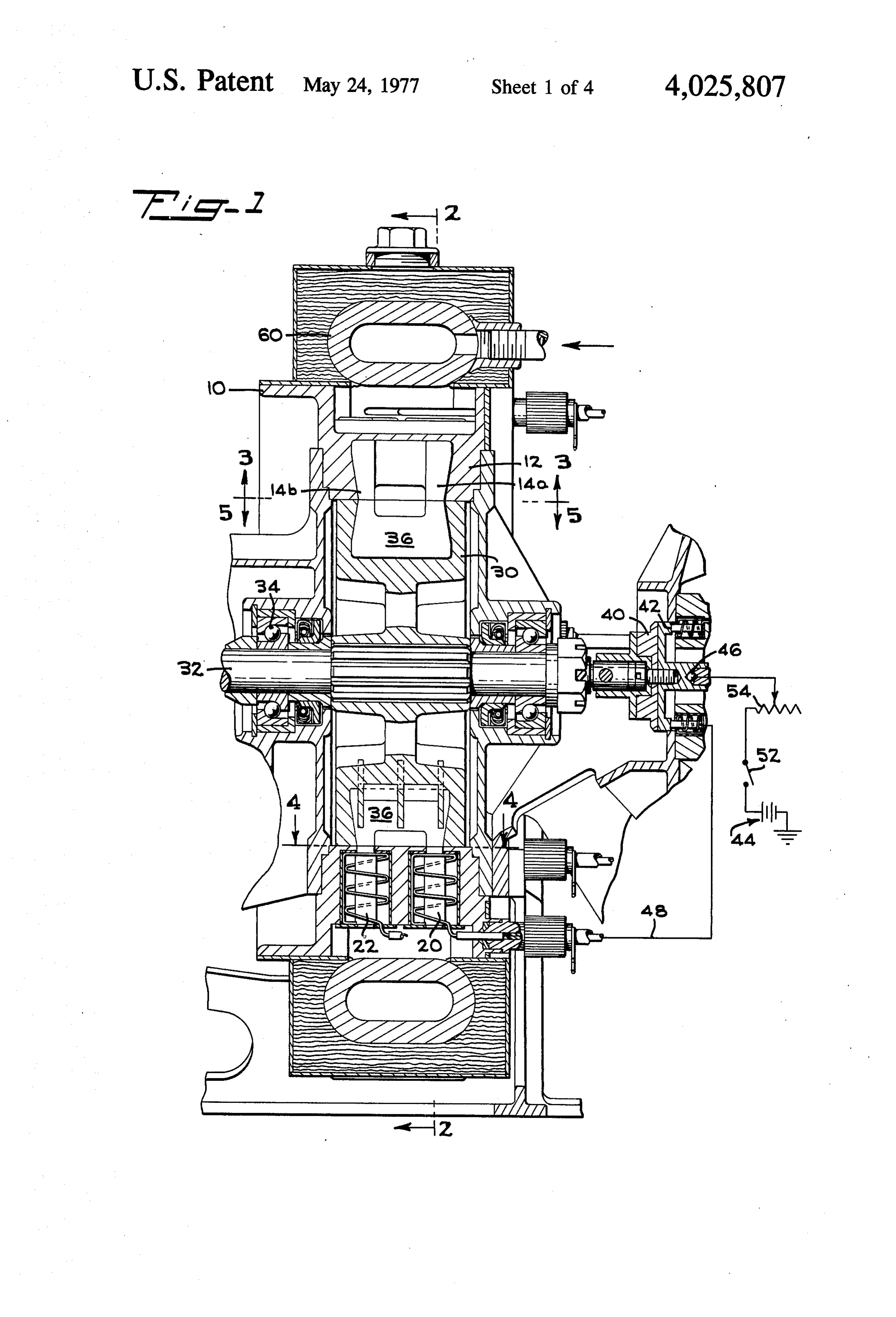
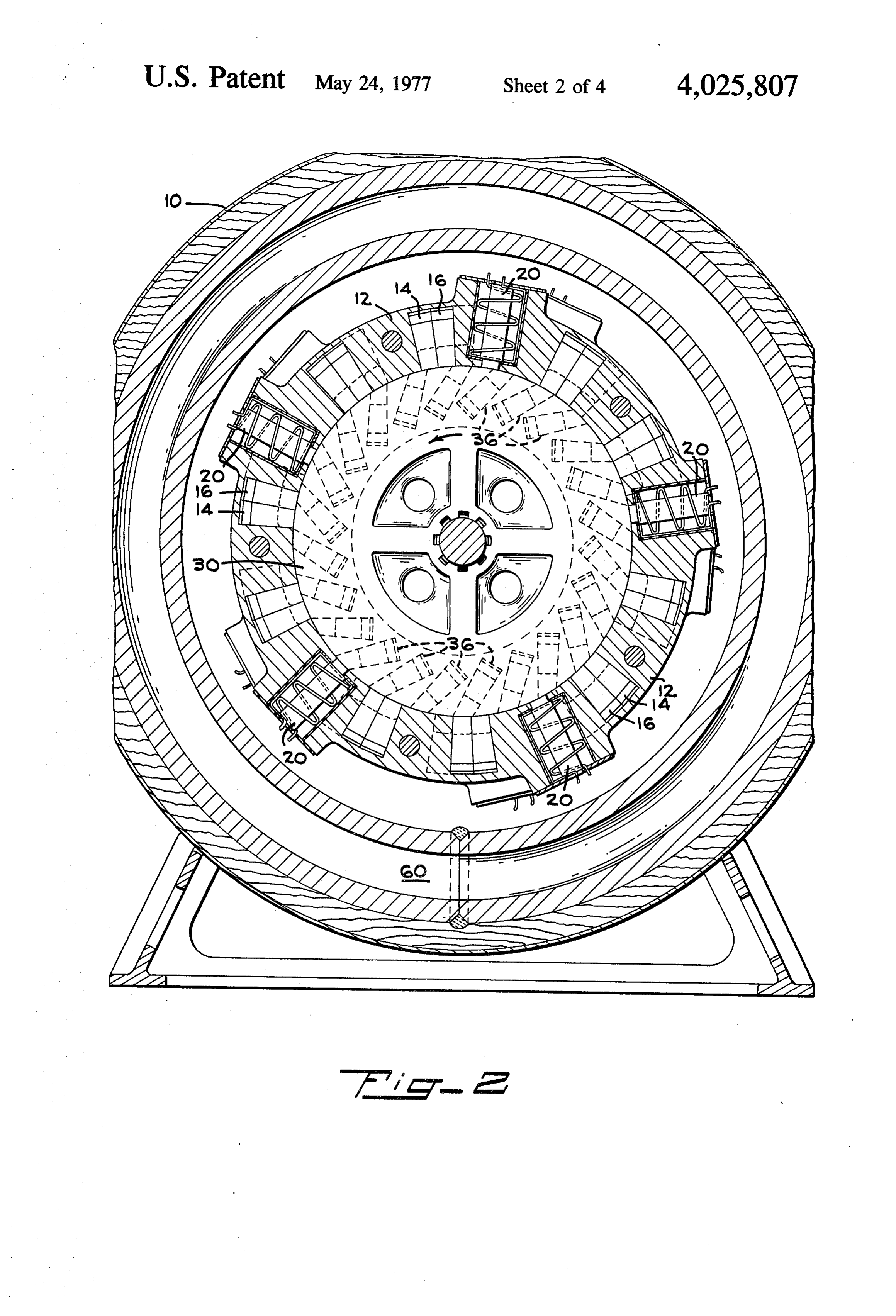
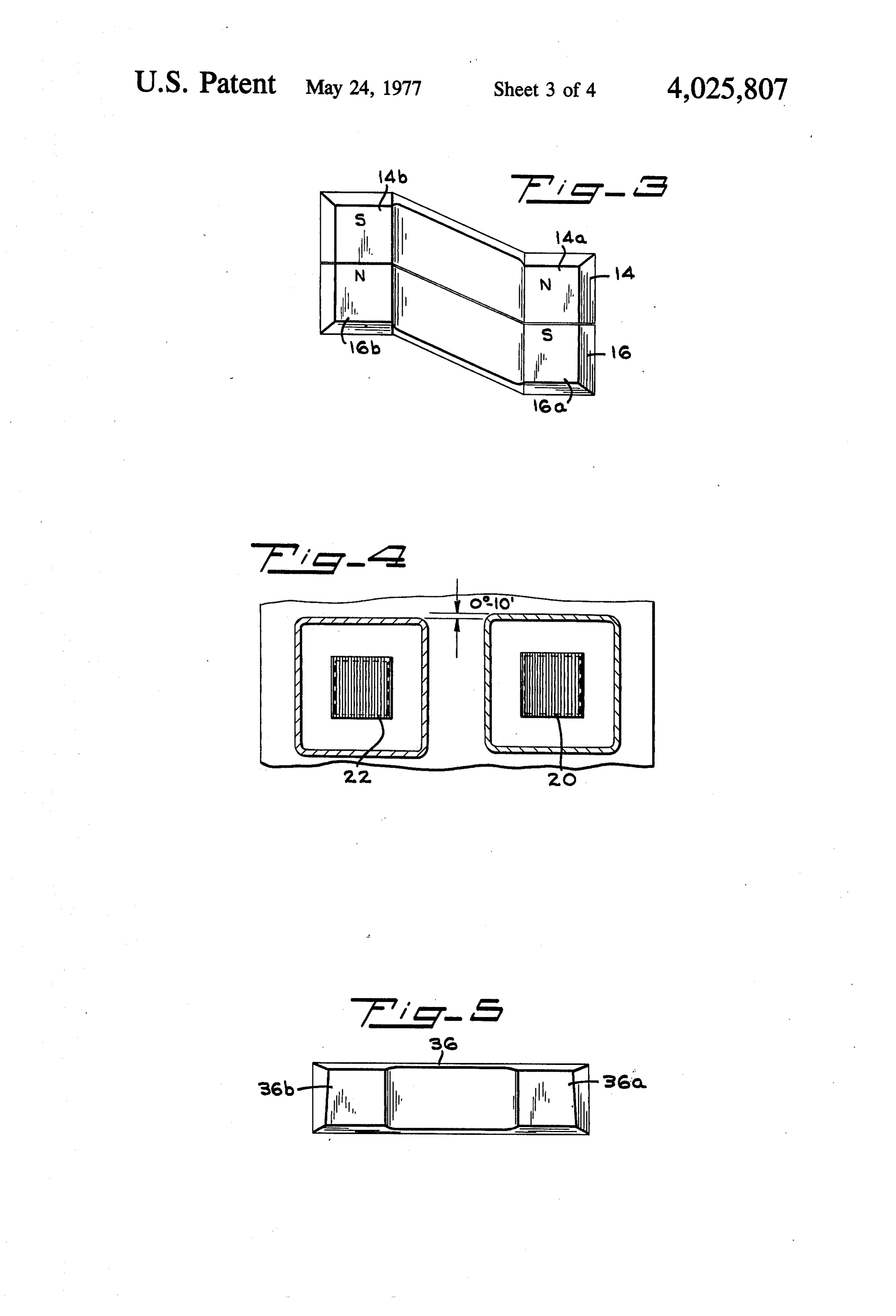
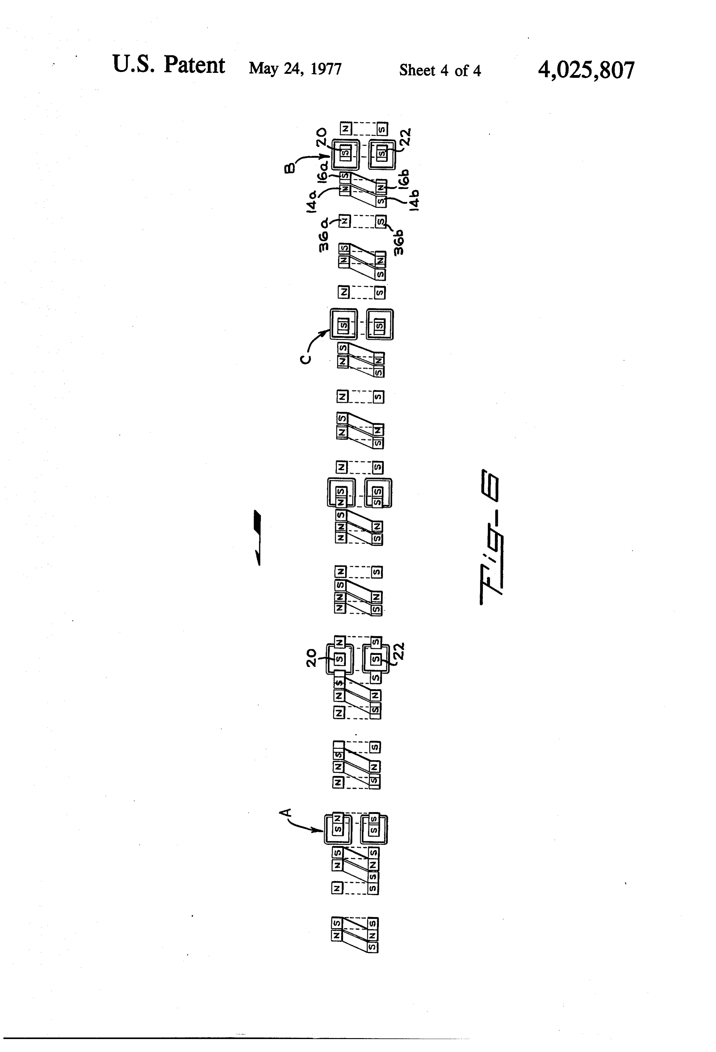
when an electromagnet on a rotor must be supplied FIG. 1 is a central longitudinal sectional view through with appropriate amounts of current. The major diffi an electromagnetic motor embodying the present in culty in all such devices prior to the present invention, vention, however, has been that of efficiency; that is, a relatively FIG. 2 is a fragmentary transverse cross-sectional large amount of electrical power input was required to 20 view taken along line 2-2 of FIG. 1, produce a given amount of rotary power or torque. FIG. 3 is a fragmentary transverse sectional view SUMMARY OF THE PRESENT INVENTION taken along line 3-3 of FIG. 1 indicating the dispo sition of the pole pieces of the permanent magnets of
Accordingly, it is the primary objective of the present the stator, invention to provide an electromagnetic motor which, 25 FIG. 4 is another fragmentary transverse sectional through utilization of permanent magnets in both its view taken along line 4-4 of FIG. 1 illustrating the stator and rotor, simplifies construction and at the disposition of the pole pieces of a pair of electromag same time provides an extremely efficient arrange nets in the stator, ment. In general terms, such objective is achieved by 30 FIG. 5 is yet a third transverse sectional fragmentary providing an electromagnetic motor having a hollow view taken along line 5-5 of FIG. 1 indicating the stator which closely encompasses a rotor. At angularly disposition of the pole pieces of the permanent magnets spaced positions, the rotor mounts a plurality of perma in the rotor structure, and nent magnets whose poles are exposed at the outer FIG. 6 is a diagrammatic linear projection of the periphery of the rotor and are accordingly in close 35 stator and rotor magnets illustrating their precise posi tional relationships at a predetermined instant, thus proximity to the surrounding stator structure. In turn, facilitating the stator also mounts a plurality of permanent magnets explanation of motor operation. at predetermined angularly-spaced positions so that DETAILED DESCRIPTION OF THE EXEMPLARY their separate poles cyclically come into alignment with EMBODIMENT OF THE INVENTION the permanent magnets, to exert magnetic attractive or 40 With initial reference to FIGS. 1 and 2, the electro repulsive forces. Such forces act at certain rotative magnetic motor embodying the present invention in positions of the rotor to exert a sum total of forces in a cludes a generally annular housing 10 formed to sup forward direction, which is that desired for motor oper port adjacent its interior periphery a generally cylindri ation. However, in other positions, the sum total of cal stator structure magnetic forces by the permanent magnets will urge 45 intervals a plurality of12pairs which mounts at 36° angular the rotor in the opposite backward direction and, at nent horseshoe magnets 14, of16closely adjacent perma in a fashion so that the such positions in accordance with the present inven exposed poles 14a, 14b, 16a, 16b of the magnets lie at tion, certain electromagnets also positioned on the stator at predetermined positions are energized so as to the interior surface of the cylindrical stator 12 in later ally-spaced and rotationally offset relationship as best exert magnetic forces in a forward direction in an 50 illustrated in FIG. 3. More particularly, the pairs of amount equal to or in excess of the forces in the back horseshoe magnets 14, 16 are in closely adjacent rela ward direction, thus allowing the rotor to continue to tionship but with reverse polarity, preferably separated revolve in the desired forward direction of motion to provide the ultimate rotary force output or torque. angularly by an air gap of 10 minutes so that a cancella tion of magnetic force exists
To assure the desired timing of the actuation of the 55 direction. The permanent magnets therebetween in a rotary electromagnets, the rotor mounts at the end of its sup 12 have their poles rotationally offset14,a 16 in the stator porting shaft, a timing disk which couples input electri alent to the length of one pole so that the Northequiv distance cal energy to such electromagnets at the desired time. of the oppositely positioned permanent magnet poles pairs Thus, whatever the speed of motor rotation, the desired are laterally aligned in a radial plane encompassing the timing of the electromagnetic actuation is assured. 60 axial center of the stator 12 so that the one South pole Control of the rotative speed is achieved by the sim is in advance of the laterally-aligned North poles and ple adjustment of the power supplied to the electro the South pole of the other permanent magnet lies magnets, and a simple switch will obviously allow the behind the laterally-aligned North poles in the direc motor to be turned “on” or “off”. The electromagnets tion of rotation.
are also positioned at appropriate angular intervals on 65 At intervening positions, five pairs of laterally-spaced the stator differing from the angular intervals of the single-pole electromagnets 20, 22, all of the same rotor magnets so that regardless of the instantaneous South polarity, are disposed at 72 intervals with five rotor disposition when the motor is turned "on', one or poles of electromagnets 20 being circularly aligned 7 with the poles 14a, 16a of the permanent magnets 14, with and this, in turn, mounts adjacent its periphery a 16 and the other five poles of the electromagnets 22 plurality of contacts 42 equal in number to the rotor being circularly aligned with the permanent magnet magnets 36 (i.e. 24) arranged upon rotation of the poles 14b, 16b as indicated both in FIG. 1 and FIG. 6. shaft 32 to provide sequential electrical connection Each right-hand pole of electromagnet 20 in the for from a suitable direct current source 44 through a ward direction of rotor rotation is positioned rear rotary ball contactor 46 to ten lead connectors 48 for wardly by a slight angle of 10 minutes relative to its the ten electromagnets 20, 22. More particularly, the companion electromagnet 22 in the direction of rota contacts 42 on the timer disk 40 each has a circumfer tion for an operational purpose to be discussed in detail ential extent which is correlated with the circumferen hereinafter. 10 tial extent of the electromagnet pole pieces and the ten With continued reference to FIGS. 1 and 2, the rotor lead connectors 48 are circumferentially positioned to 30 of the exemplary embodiment of the invention is sequentially energize the electromagnets. Specifically, mounted on a suitable shaft 32 that is, in turn, rota signal contact is made with respective electromagnet tively supported by conventional bearings 34 for rota lead connector 48 precisely at the position where a tion within the stator 12 with the exterior periphery of 15 rotor magnet pole 36a has centered with the lead the rotor being closely adjacent to the interior cylindri (South) pole of a permanent stator magnet pole 14a cal surface of the described stator 12, a typical clear immediately in advance thereof in the direction of ance being 0.010 inch. This rotor 30 mounts at regular rotor rotation. Thus, the top electromagnet 20 as indi circumferential intervals of 15° a plurality (24) of like cated at A at the left in FIG. 6 is about ready to be horseshoe magnets 36 whose laterally-spaced poles 20 energized thus to exert an attractive force on the adja 36a,36b are exposed at the outer periphery of the rotor cent North pole 36a of the rotor magnet to overcome so as to have strong magnetic interaction with the poles the locking magnetic attraction experienced by the of both the permanent magnets 14, 16 and the electro rotor magnet North pole immediately in advance magnets 20, 22 in the stator 12. These magnets 36 are thereof which lies opposite the leading South pole 14a identical with all of their North poles 36a being aligned 25 of the permanent magnet on the stator 12. The top in one circular plane which is in turn aligned with the electromagnet 20 continues to be energized through adjacent poles 14a, 16a, 20 of the permanent magnets the attracting position indicated at position B at the and the electromagnets for interaction therewith and right of FIG. 6 and until the North pole 36a of a rotor the laterally or axially-displaced South poles 36b of the magnet lies opposite the pole of the energized electro rotor permanent magnets being in a circumferential 30 magnet as indicated at position C, at which time plane which is in turn aligned with the poles of the contact on the timer disk 40 is lost and this electromag other electromagnets 22 and the laterally-displaced net 20 is accordingly de-energized. Simultaneously poles 14b, 16b of the permanent horseshoe magnet with the de-energization of the upper electromagnet pairs. Preferably, the rotor permanent magnets 36 are 20, its companion electromagnet 22 which is adjacent supported in the rotor so as to individually slope ap 35 the South pole 14b of the permanent magnet on the proximately 30 rearwardly and outwardly relative to rotor 30 is now energized. However, since this electro the direction of rotor rotation which, as indicated in magnet 22 is angularly displaced by 10 minutes, the FIG. 2, is counterclockwise. repulsive force between the South pole of the electro Bearing in mind that opposite magnetic poles attract magnet and the adjacent South pole 14b of the rotor and like poles repel, it will be clear from a cursory view 40 permanent magnet creates a repulsive force again tend of the diagrammatic linear presentation of FIG. 6 that ing to move the entire rotor to the left as viewed in FIG. certain of the rotor magnets 36 will be urged in the 6. Such repelling action continues until the South pole forward rotative direction which is, as previously men 14b of the permanent magnet extends beyond the ener tioned, counterclockwise in FIG. 2, and, as indicated gized South pole of the electromagnet 22 at which time by the arrow, is towards the left in FIG. 6 by certain of 45 both the North and South poles of the preceding per the permanent magnets 14, 16 in the stator 12 whereas manent magnets 36 on the rotor are beyond the corre other rotor permanent magnets 36 will experience ei sponding North and South poles of the stator perma ther attractive or repulsive forces so as to be urged in nent magnets 14, 16 whereat the latter will continue to act in a repelling action to continue the advance of the the opposite rotative direction. In accordance with the 50 rotor present invention, the described electromagnets 20, 22 in the desired forward direction or to the left as in the stator 12 are energized at appropriate times to shown in FIG. 6. Thus, in summary it will be seen that overcome magnetic forces urging the rotor 30 opposite the electromagnets 20, 22 are cyclically activated to to the forward direction thus providing continued rota overcome any forces of the stator permanent magnets tion of the rotor in the desired forward direction and 14, 16 which tend to retard rotor rotation or move the the ultimate production of mechanical torque by way 55 rotor 30 in the direction opposite to the desired for of the rotor shaft 32 which can be suitably connected to ward direction, and thereafter the electromagnets 20, any output mechanical load in a conventional fashion. 22 are de-energized to allow the permanent magnets More particularly, and as can be readily visualized by forces 14, 16 to act in a fashion to continue action of magnetic reference to FIG. 6, the angular spacing of the electro so as to advance the rotor 30 in the desired magnets 20, 22 (72) differs from the spacing of the 60 forward While direction.
the precise power requirements for any partic rotor magnets 36 (15') or any multiple thereof, in par ticular, the multiple of five or 75°. Consequently, each ular motor will obviously vary, it is preferred that the electromagnet 20, 22 is in a different position relative exterior source 44 of the D.C. potential be at a rather to each generally adjacent rotor magnet 36, thus allow low value (e.g. 12 volts) where it is delivered to the ing sequential energization of the electromagnets in 65 timer disk 40 and associated contacts but thereafter be appropriate order to advance the rotor. fed to a suitable voltage amplifier 50 so that appropri For the described purpose, one end of the rotor shaft ate excitation of the electromagnets 20, 22 in the 32 mounts an annular timer disk 40 for rotation there timed-cycle relation will be sufficient to overcome any 8 retarding action of the permanent magnets 14, 16 of said stator also mounting a plurality of electromag the stator. nets in predetermined positions to provide attrac Additionally, as indicated in FIG. 1, a switch 52 and tion and repulsion forces on said rotor magnets, a rheostat 54 are preferably connected in the circuit to and the exterior direct current source 44, the switch 52 5 means for periodically energizing said electromag enabling the motor to be turned on or off and the rheo nets to generate forces on said rotor to propel the stat 54 controlling the voltage applied to the electro same in a forward direction when the forces of said magnets 20, 22 to in turn provide for variable speed of stator permanent magnets on said rotor magnets the motor. urge said rotor in a backward direction, Due to the combined application of forces to the 10 said rotor permanent magnets having identical horse rotor 30 by both permanent magnets and electromag shoe magnets similarly mounted on said rotor nets, the overall motor efficiency is very high as com whereby the North poles of said magnets are circu pared to prior art units and can be extended by utiliza larly aligned around said rotor periphery and the tion of the principles of superconductivity wherein, as 15 South aligned, poles of said magnets are also circularly is well known in the field of physics, lowering of the said stator permanent magnets being composed of temperature of electrical conductors and magnets in adjacent pairs of horseshoe magnets whose poles creases their effectiveness through lowering of resis are of opposite polarity and are circularly aligned tance losses. By way of example, in the present in with the poles of said rotor permanent magnets, stance, and as best shown in FIGS. 1 and 2, an exterior 20 said electromagnets having like poles when energized channel 60 is provided around the stator 12 enabling and consisting of first and second laterally-spaced the passage of super-cooled fluid therethrough, thus to sets, each aligned circularly with said rotor and reduce the temperature of motor operation and stator permanent magnet poles, and achieve the desired superconductive effects which in said electromagnets of the first set which attract the and of themselves form no part of the present inven 25 rotor magnets when energized being spaced for tion, although in the combination the ultimate in motor wardly a small amount substantially less than the efficiency is thereby achieved. dimension of one pole in the direction of rotor It is obvious that many modifications in the structur rotation relative to said electromagnets of the sec as described can be made within the spirit of the inven ond set which repulse said rotor permanent mag tion. For example, fewer or more magnets can be uti 30 nets when energized.
lized and, in particular, a group of units as specifically 2. An electromagnetic motor according to claim 1 described hereinabove can be placed in side-by-side wherein relation on a common output shaft to multiply the total said poles of said stator magnet pair are offset in the torque obtainable from a given unit. The described 35 direction of rotor rotation a distance equivalent to stator and rotor arrangements allow such side-by-side the dimension of one pole in such rotative direc utilization of identical units without substantial rede tion.
sign or modification and, of course, are to be encom wherein 3. An electromagnetic motor according to claim 1 passed within the general spirit of the invention. Ac cordingly, with these and other obvious modifications the angular spacing of said stator electromagnets in mind, it is to be specifically noted that the foregoing 40 differs from the angular spacing of said rotor mag nets or any multiple thereof.
description of one embodiment of the invention is not 4. An electromagnetic motor according to claim 1 to be considered in a limiting sense and the actual scope of the invention is to be indicated only by refer wherein said rotor mounts 24 permanent magnets at angular ence to the appended claims. 45 intervals of 15, and
What is claimed is
1. An electromagnetic motor which comprises said stator mounts said permanent magnets in 10 a rotor having a plurality of permanent magnets at pairs at intervals of 36, and said electromagnets in regularly spaced positions on its periphery, 5 pairs at intervals of 72. 5. An electromagnetic motor according to claim 1 a stator closely encompassing said rotor and mount 50 wherein ing a plurality of permanent magnets in predeter said electromagnet energizing means energizes said mined positions to provide cyclical attraction and electromagnets xin predetermined sequence. repulsion forces on said rotor magnets, k is k k
Provenance
- Collection
- Patents citing this work
- Pages
- 8
- Method
- pdftotext (the PDF's own text layer) + pdftoppm 300dpi page scans
- Patent office record
- patents.google.com →
- Source
- Google Patents citing-documents table
- Assignee
- Clover Leonard W
- Published
- 1977-05-24
- Transcribed from
- patentimages.storage.googleapis.com →