

patent · US4026747A
Composite tubing
31 May 1977
Text
Page 1bibliographic recordscan →
United States Patent (19)
DeLorean et al.
(54) COMPOSITE TUBING
(75) Inventors: John Z. DeLorean, Bloomfield Hills;
Chauncey L. Dirks, Metamora, both of Mich.
Assignee: John Z. DeLorean Corporation,
Bloomfield Hills, Mich.
Related U.S. Application Data
52 U.S. Cl. ............................... 156/171; 156/172;
Int. Cl”......................................... B65H 81/00
UNITED STATES PATENTS
2,120,426 6/1938 Herrmann ....................... 186/77 X 3,194,274 7/1965 Griffiths et al. ............... 138/144 X.
3,215,576 1 1/1965 Huff .................................. 1561162 3,562,085 2/1971 Crandal et al. ................ 428/252 X 3,651,661 3/1972 Darrow .......................... 138/144 X 3,728,187 4/973 Martin ........................... 138/144 X
FOREIGN PATENTS OR APPLICATIONS
Primary Examiner-David A. Simmons
Attorney, Agent, or Firm-Reising, Ethington, Barnard, Perry & Brooks
The invention relates to the fabrication of composite rigid tubular structures which include a rigidified tubu lar core member, an initially open-cell resilient foam material helically wrapped about the core member, a layer of reinforcing elements helically wrapped about and radially compressing said foam material, and a thermoset resinous matrix filling the compressed open cells of said foam material and encapsulating said rein
2 Claims, 6 Drawing Figures
Drawings
Page 2drawing sheetscan →
Page 3drawing sheetscan →
Page 4drawing sheetscan →
Page 5scan →
foam layer whereby the resin matrix is distributed
COMPOSITE TUB ING throughout the various layers.
More specifically, the invention contemplates form ing,
This is a division, of application Ser. No. 545,683 5 formed as by extrusion, a continuous tubular core element filed Jan. 30, 1975. of a plastic material such as polyvinyl chloride which has alternate layers of resin impregnated open
BACKGROUND OF THE INVENTION cell foam and reinforcing filaments alternately wrapped The present invention relates to the manufacture of thereabout. The open-cell foam may be of resilient reinforced plastic pipe of high strength and which pipe polyurethane strips wherein the cells are in open com can be fabricated in relatively continuous lengths. 10 munication with each other. The reinforcing elements Rigid pipe fabricated in accordance with this invention may be made of fiberglass either stranded or of mono is intended for use in transmitting high pressure liquids filament construction. The impregnating resin is of a or gases and under conditions where metal pipes would thermosetting variety and typically can include epoxy be subjected to corrosion both by the material being or polyester resins.
transmitted and the ambient operating environment. 15 foam In order to fill substantially all the open-cells of the It is a further objective of the invention to provide a layer with the thermosetting resin and also to rigid pipe that is substantially lighter in weight than encapsulate the filaments with the resin, means is pro metal pipe of corresponding capacity for greater ease vided for forcing the filaments radially inwardly to of handling and the unique construction of which per compress the foam layer and to maintain said com mits fabrication in substantially longer lengths than 20 pressed condition while applying heat to harden the heretofore known types of metal or reinforced plastic resin matrix.
pipes. Such radial compressing function may be achieved through the use of a sizing die means which additionally
PRIOR ART DEVICES enhances the impermeability of the resin matrix, re Reinforced high strength pipes have heretofore been 25 moves excess resin and controls the external smooth made in relatively short lengths due to the method by ness of the finished pipe.
which they are formed. Such pipe is normally made by In providing a unique high strength plastic pipe de wrapping alternate layers of resin coated high strength sign which avoids the need to use a rotatable and re materials or filaments, such as fiberglass, about a man movable mandrel in its fabrication, it is possible to drel and with adjacent filament layers being laid on 30 make long or substantially continuous pipe lengths at opposite helical leads. After sufficient pipe thickness is the site where the pipe is to be used and thereby greatly achieved through the application of alterriating layers, reducing the number of pipe couplings required and the pipe must be removed from the mandrel. Normally, associated labor.
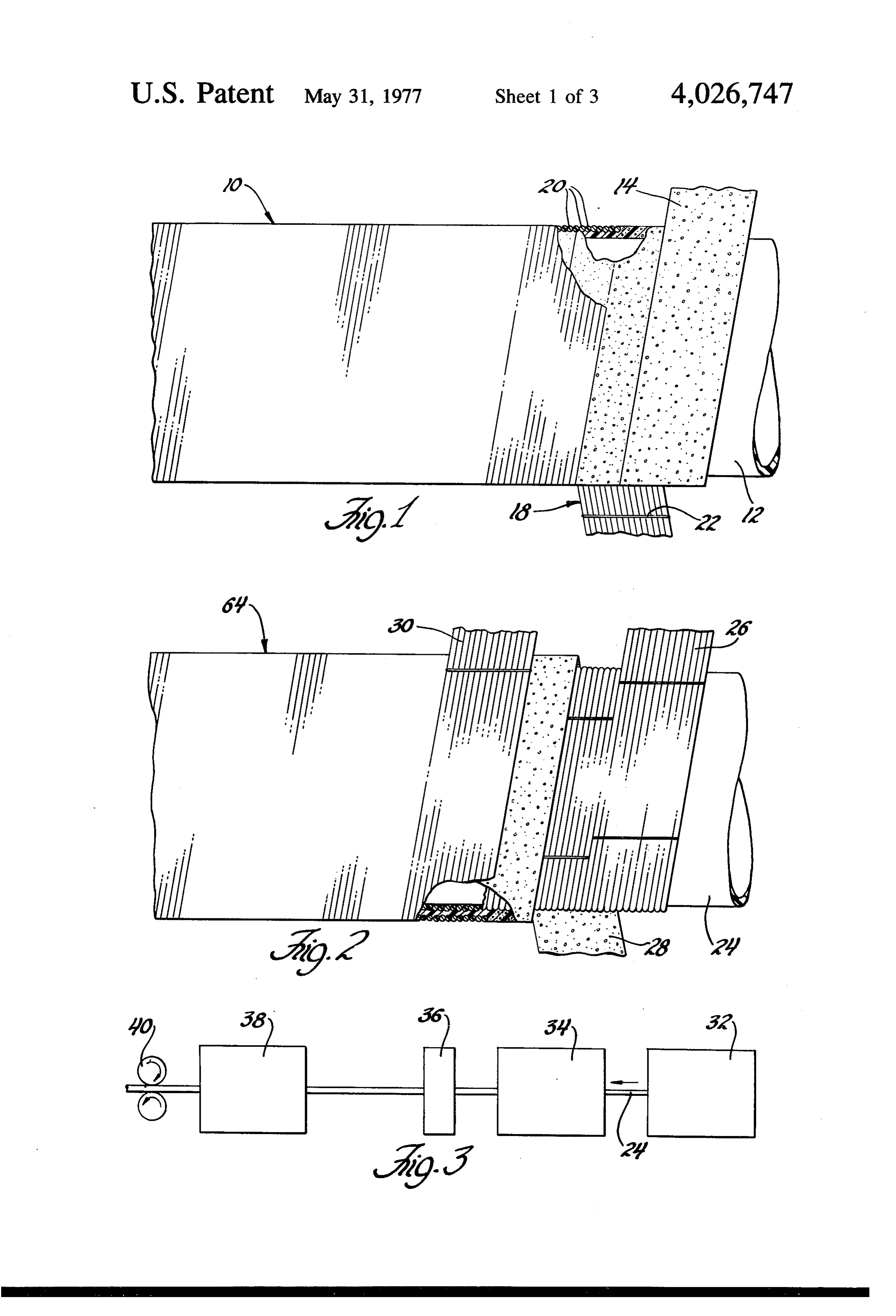
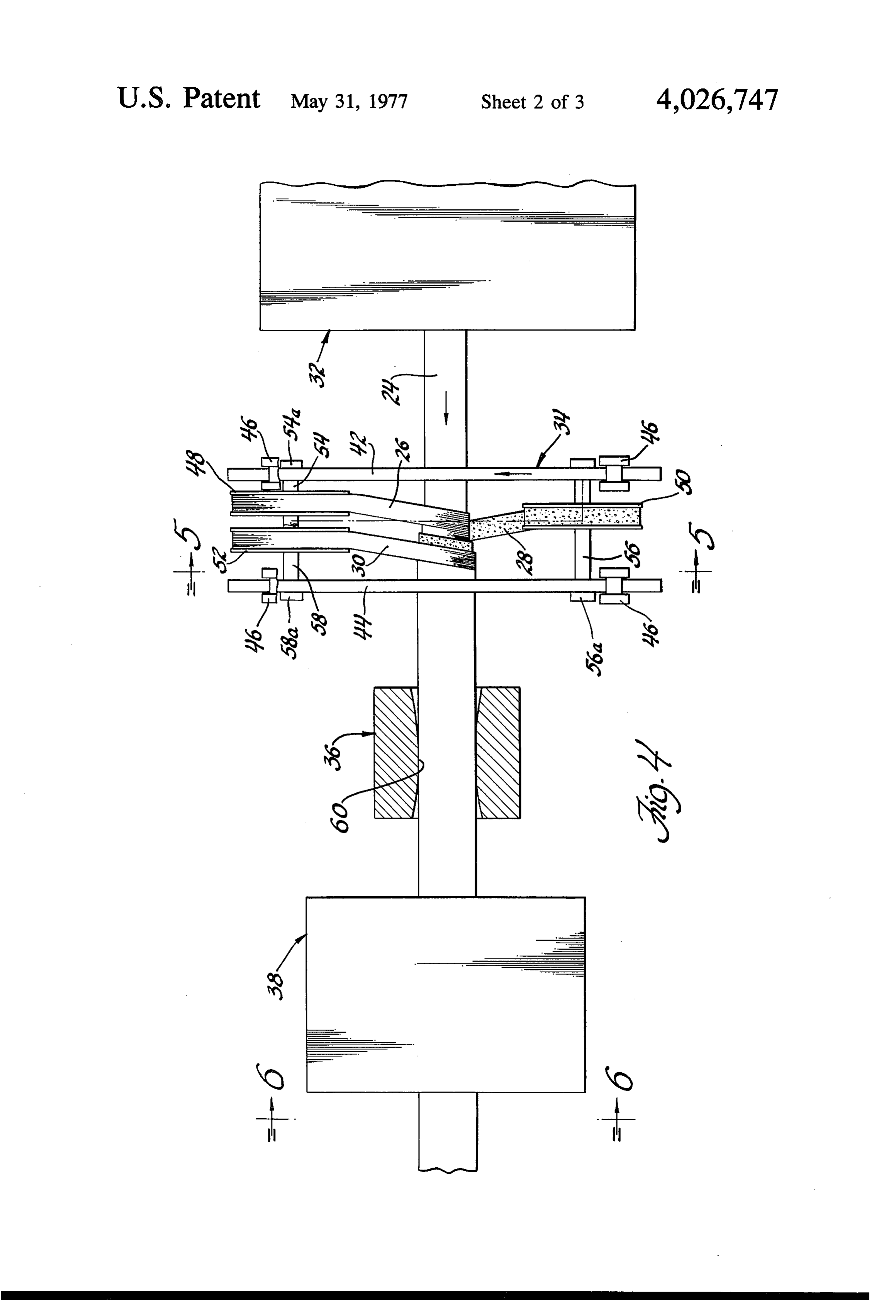
the high strength filaments of each layer are pre-coated Referring now to the drawings: with thermosetting resin by passing the same through a 35 FIGS. 1 and 2 are partially sectioned views showing resin bath just prior to wrapping the filaments about the two modifications of reinforced pipe made in accor mandrel. By normal practice the mandrel is rotated and dance with the invention.
the filaments applied by traversing along the length of FIG. 3 is a block diagram showing the various steps in the mandrel with the direction of travel being reversed 40 the method of making pipe in accordance with the invention.
as the filaments approach each end of the mandrel.
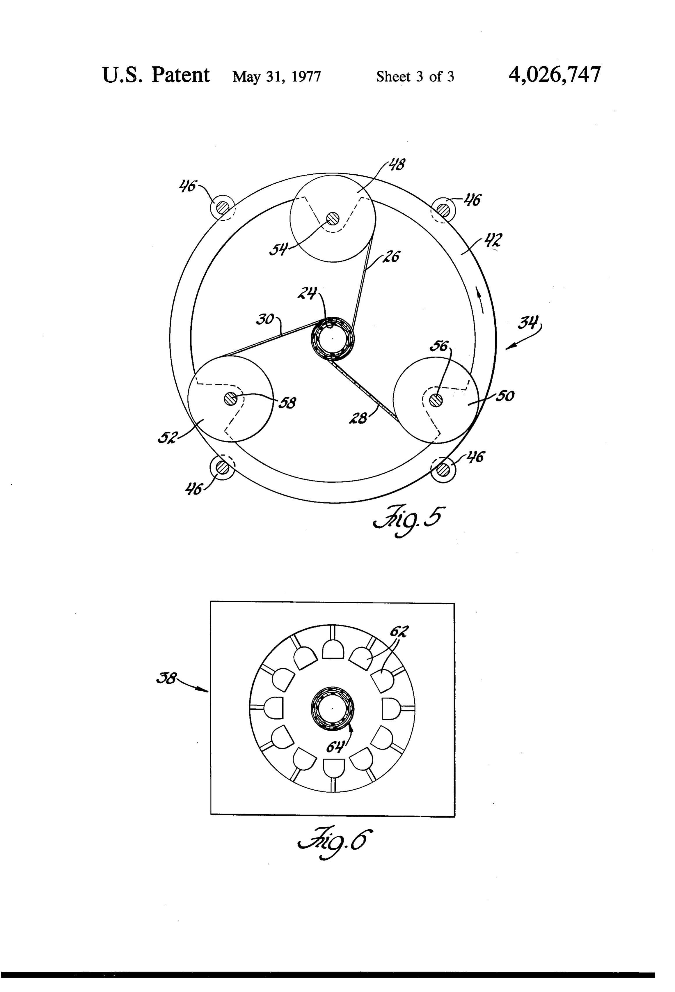
With the use of a rotating mandrel and criss-crossing FIG. 4 shows in greater detail an illustrative appara reinforcing layers, the length of pipe sections which can tus for making pipe in accordance with the invention. be made has been limited. FIGS. 5 and 6 are views along lines 5-5 and 6-6 of
PRESENT INVENTION 45 Referring to FIG. 1, a composite reinforced plastic High strength reinforced plastic pipe made in accor pipe made in accordance with the invention is indi dance with the present invention avoids the use of a cated generally at 10. A rigidified tubular member 12 rotating mandrel and thereby enables the pipe to be provides a core element which, while forming an inte made in relatively long or continuous lengths. The gral part of the composite pipe, also provides a mandrel present invention utilizes a continuously formed rigidi 50 function about which subsequent layers of reinforcing fied tubular core member overlaid with alternate layers materials are wrapped. Tubular core member 12 may of thermosetting resin-impregnated open-cell foam be formed by any continuous process, such as extrud strips and reinforcing filaments applied in such a way as ing, from any suitable thermosetting material, such as to radially compress the impregnated foam to force the polyvinyl chloride. It is important that core element 12 resin to fill the open-cell structure and to expel excess 55 be formed with a sufficient wall thickness so as to be resin so as to encapsulate the reinforcing filaments. relatively rigid and not subject to collapsing as subse While maintaining the composite in the radially com quent layers of material are wrapped thereabout. In this pressed condition, heat is applied to cure the resin and modification of the invention, a first layer of a resilient thereby provide an impervious hardened resin matrix open-cell foam material 14, such as polyurethane, is extending throughout the foam and reinforcing layers. 60 wrapped about core element 12. Prior to mounting on The number of alternate layers of reinforcing elements a storage drum or reel such as shown in FIG. 5, the and open-cell foam utilized in fabricating pipe in accor open-cell foam material 14 is partially, e.g. 50%, im dance with the invention can be varied depending on pregnated with a thermosetting resin material such as structural strength and permeability requirements. epoxy or polyester. To impregnate the open-cell foam Basic to the inventive concept is the use of a rigidified 65 material 14, an open-cell polyurethane strip is run tubular core member overlaid by at least one resin through a suitable tank filled with the thermosetting impregnated open-cell foam layer and a layer of rein resin and thereafter passed through doctoring rolls to forcing filaments applied so as to radially compress the squeeze out excess resin and leave the strip only par 6 tially impregnated and, therefore, relatively dry at the mechanism 40. The various devices constituting the outer surfaces and storable on reels or drums. . composite pipe forming apparatus will now be de As indicated at the right hand side of FIG. 1, the scribed in greater detail and by reference to FIGS. 4 impregnated foam layer 14 is laid on core element 12 in through 6.
an uncompressed condition and with the cells thereof 5 theReferring first to FIG. 6, it should first be noted that various devices making up the pipe forming appara in open communication with each other and partially tus are disposed in line to facilitate the forming of a filled with the thermosetting resin. A layer of reinforc straight length of composite pipe and can be mounted ing fiberglass filaments is indicated generally at 18.
Depending on the ultimate strength required for the on a common bed or platform, not shown, so that the composite pipe, the reinforcing layer may be either of 10 apparatus may be moved as a single entity facilitating a woven cloth configuration, a mat swirl or unidirec its movement from site to site.
tional filaments 20 as shown in FIG. 1. The unidirec Extruder 32 is of a conventional screw or helix type tional filaments are preferred in that they provide whereby tubing may be extruded in a continuous length greater hoop strength to the finished pipe. The unidi therefrom. Inasmuch as it is necessary that tubular core rectional fiberglass filaments 20 can be provided in 15 elements 12 or 24 be rigid prior to entering the wrap strip form as shown in the drawings and wherein the clude ping device 34, extruder 32 would probably also in filaments are lightly held together by suitable cross a suitable chilling or cooling device not specifi thread elements 22 spaced along the length of the strip. cally shown.
Filament strip 20 is mounted on a suitable reel which As the rigidified tubular core element 24 leaves the is, in turn, maintained under a tension load whereby in 20 extruding station, it next passes through the wrapping being wrapped about the impregnated foam layer 14, device 34. In describing wrapping device 34 particular filament strip 20 is moved radially inwardly against the reference should be made to FIGS. 4 and 5. Wrapping resilient foam layer so as to compress the latter to ap device 34 includes a pair of axially spaced disc mem proximately one-half of its original thickness. In thus bers 42 and 44 suitably interconnected for rotation on compressing the foam layer 14, the resin contained 25 supporting rollers 46. Discs 42 and 44 are concentri therewithin is extruded throughout the open-cell foam cally disposed relative to the axis of tubular core ele structure so as to fill substantially all of the now com ment 24. One or more of the supporting rollers 46 is pressed cells with the thermosetting resin and with the connected to a drive mechanism, not shown, whereby excess of said resin being expelled radially outwardly the discs may be rotated relative to the tubular core through the reinforcing layer so as to encapsulate the 30 element 24. Incidentally, the speed of rotation of discs individual filaments in said resin. Thus, the thermoset 42-44 is coordinated with that of pipe driving mecha ting resin is squeezed to provide a matrix extending nism 40 to regulate the manner in which the various throughout the foam and filament layers. helical layers are applied to core element 24. Wrapping Where a higher strength composite pipe is required, device 34 includes a plurality of storage reels 48, 50 additional layers of reinforcing elements may be uti- 35 and 52 respectively mounted on shafts 54, 56 and 58 lized, as shown in FIG. 2. In this case, the rigidified and which are, in turn, rotatably supported between the plastic core element 24 is wrapped with a first strip of disc members 42 and 44. While shown as being sub reinforcing elements 26 which is overlaid with a layer stantially parallel to the axis of tubular core element of resin impregnated resilient foam 28 which, in turn, is 24, the axes of shafts 54, 56 and 58 may be slightly wrapped with a second strip of reinforcing elements 30. 40 inclined to the core element axis if necessary to facili Once again, the reinforcing strip 30 is maintained tate wrapping layers 26, 28 and 30 upon the core ele under sufficient tension or drag to substantially reduce ment.
the thickness of foam layer 28 thereby filling substan Reel 48, which is axially disposed closest to extruder tially all the open-cells thereof and to expelling excess 32, contains a first supply of unidirectional reinforcing resin so as to encapsulate layers 26 and 30 therein. 45 filaments 26. Reel 50 contains a supply of the partially In both of the modifications of FIGS. 1 and 2, addi resin-impregnated resilient open-cell foam strip 28 and tional means may be provided, infra, to create an addi is disposed axially intermediate reels 48 and 52. Reel tional radial compressive force on the various pipe 52 contains the second supply of unidirectional rein layers to insure that all the foam cells are filled and forcing filament strip 30. By reference to FIG. 5, it will reinforcing elements encapsulated prior to heat curing 50 be noted that reels 48,50 and 52 are circumferentially the resin. spaced at approximately 120 from each other. For The process and an illustrative apparatus for forming ease of illustrating the laying of strips 26, 28 and 30 the composite pipe will now be described. about core element 24, the reels 48, 50 and 52, as FIG.3 is a diagrammatic representation of an appara shown in FIG. 4, have been circumferentially displaced tus for forming the composite pipe in accordance with 55 from their actual and symmetrical positions on discs 42 the invention and specifically the modification of FIG. and 44, as properly shown in FIG. 5. 2. The details of the various devices included in the Each of the reel shafts 54, 56 and 58 includes a apparatus of FIG. 3 are shown in FIGS. 4 through 6. breaking device 54a, 56a and 58a to create a drag or Referring first to FIG. 3, the in line apparatus in tension load to adjustably control the tightness with cludes an extruder 32 for continuously forming the 60 which each of the various layers is laid down upon rigidified tubular core element 24, a wrapping device tubular core element 24. Thus, as discs 42-44 are ro 34 for applying reinforcing filament layers 26 and 30 as tated relative to the axially moving tubular core ele well as an intermediate resilient open-cell foam layer ment 24, layer 26 of reinforcing elements is wrapped 28. After leaving the wrapping device 34 the wrapped about the core element and is, in turn, overlaid with core element passes through a sizing die 36 prior to 65 resin impregnated foam layer 28 which is then overlaid entering a heating device 38 wherein the thermosetting by the second layer of reinforcing elements 30. resin is hardened. The composite pipe is drawn through The drag or frictional load on reel 52 is suitably ad the aforementioned apparatus by a suitable driving justed to insure that the outer layer of reinforcing ele 7 ments 30 is drawn radially down against the subadja 1. The method of making a composite tubular struc cent foam layer 28 to compress the same to approxi ture comprising longitudinally moving a rigidified con tinuous tubular core member, impregnating a strip of mately one-half of its original thickness, as best seen in open-cell resilient foam material with a thermosetting the cut-away section of FIG. 2. resinous material, wrapping said impregnated foam The strength and impermeability of the resultant strip about said core member, wrapping a layer of rein composite pipe is importantly effected by the distribu tion of the hardened resin matrix throughout the vari forcing elements about said foam material, urging said reinforcing elements radially inwardly to compress said ous layers overlaid on the tubular core element 24. foam material thereby causing said resinous material to Accordingly, sizing or compressing die 36 is provided.
Die 36 is concentrically disposed about tubular core 10 fill the cells of said materials and to expel excess resin element 24 and includes an inner bore 60 of such a size ous material therefrom to encapsulate said reinforcing as to insure that outer reinforcing layer 30 suitably elements in said resinous material, and applying heat to compresses foam layer 28 to extrude the thermosetting hardened said resinous material while maintaining said resin matrix throughout the layers as described. The foam in a compressed condition.
sizing die performs the additional functions of renov 15 ture2. The method of making a composite tubular struc ing excess resin, which can be suitably collected, and comprising longitudinally moving a rigidified con smoothing the exterior pipe surface. tinuous tubular core member, impregnating a strip of Following passage through the compressing or sizing open-cell resilient foam material with a thermosetting die 36, the wrapped pipe now passes through heating resinous material, wrapping said impregnated foam device 38 where the resin is hardened. Referring more 20 strip about said core member, wrapping a layer of rein specifically to FIG. 6, heating device 38 may be com forcing elements about said foam material, urging said prised of any suitable heat source such as infra red reinforcing elements radially inwardly to compress said lamps 62 circumferentially disposed about the compos foam material thereby causing said resinous material to ite pipe 64. fill the cells of said material and to expel excess resin It is to be understood that various modifications may 25 ous material therefrom to encapsulate said reinforcing be made to the structures, apparatus and process within elements in said resinous material, circumferentially the intended scope of the invention as set forth in the compressing and wiping the wrapped and encapsulated hereinafter appended claims. reinforcing elements to remove excess resinous mate The embodiments of the present invention in which rial, and applying heat to harden said resinous material an exclusive property or privilege is claimed are de 30 while maintaining said ck foam in ak compressed condition.
fined as follows:
Provenance
- Collection
- Patents citing this work
- Pages
- 7
- Method
- pdftotext (the PDF's own text layer) + pdftoppm 300dpi page scans
- Patent office record
- patents.google.com →
- Source
- Google Patents citing-documents table
- Assignee
- John Z. Delorean Corporation
- Published
- 1977-05-31
- Transcribed from
- patentimages.storage.googleapis.com →