

patent · US4029080A
Thermal collector of solar energy adapted for high temperature operation
14 June 1977
Text
Page 1scan →
United States Patent (19)
Warren
54 thermal collector of solar
Energy adapted for hgh
Temperature operation
(75 Inventor: Roger W. Warren, Pittsburgh, Pa.
(73) Assignee: Westinghouse Electric Corporation,
Pittsburgh, Pa.
(52) U.S. Cl. ................................ 126/270; 126/271
I51) Int. C.’............................................ F24J 3/02 58 Field of Search ............................ 126/270, 271
United states patents
679,451 7/1901 Baker ................................ 126/27
2,213,894 9/1940 Barry ................................. 126/271 2,918,709 12/1959 Corcoran ........................... 126/270 3,250,269 5/1966. Sherock ............................. 126/27 3,893,506 7/1975 Laing................................. 126/271 3,894,369 7/1975 Schmitt et al. .................... 126/270 3,918,430 1 1/1975 Stout et al. ........................ 126/271
Primary Examiner-Lloyd L. King
Attorney, Agent, or Firm-E. F. Possessky
A thermal collector of solar energy that is adapted for installation in the roof structure of a building includes a cover plate to transmit sunlight, a backing, and an energy-absorbing material carried by the backing, to absorb energy of the transmitted sunlight and to trans fer heat of such absorbed energy to the backing. A heat transfer medium delivers heat from the backing to a heat using apparatus such as a building heating or air conditioning system or a heat pump. The backing is designed to limit the weight of the collector and to improve its rate of thermal response upon reappear ance of the sunlight. For purposes of limiting heat losses from the backing to the cover plate, the collector is evacuated and components that connect the backing with the cover plate are designed for low heat flow. Thus heat is delivered to the heat using apparatus at an elevated temperature of the heat transfer medium for improved efficiency of such apparatus.
15 Claims, 9 Drawing Figures
Drawings
Page 2drawing sheetscan →
Page 3drawing sheetscan →
Page 4drawing sheetscan →
Page 5drawing sheetscan →
Page 6scan →
tive and convective heat losses from the backing
THERMAL COLLECTOR OF SOLAR ENERGY through such space to the window, whereby the operat ADAPTED FOR HGH TEMPERATURE ing temperature of the backing is raised. OPERATION BRIEF DESCRIPTION OF THE DRAWINGS
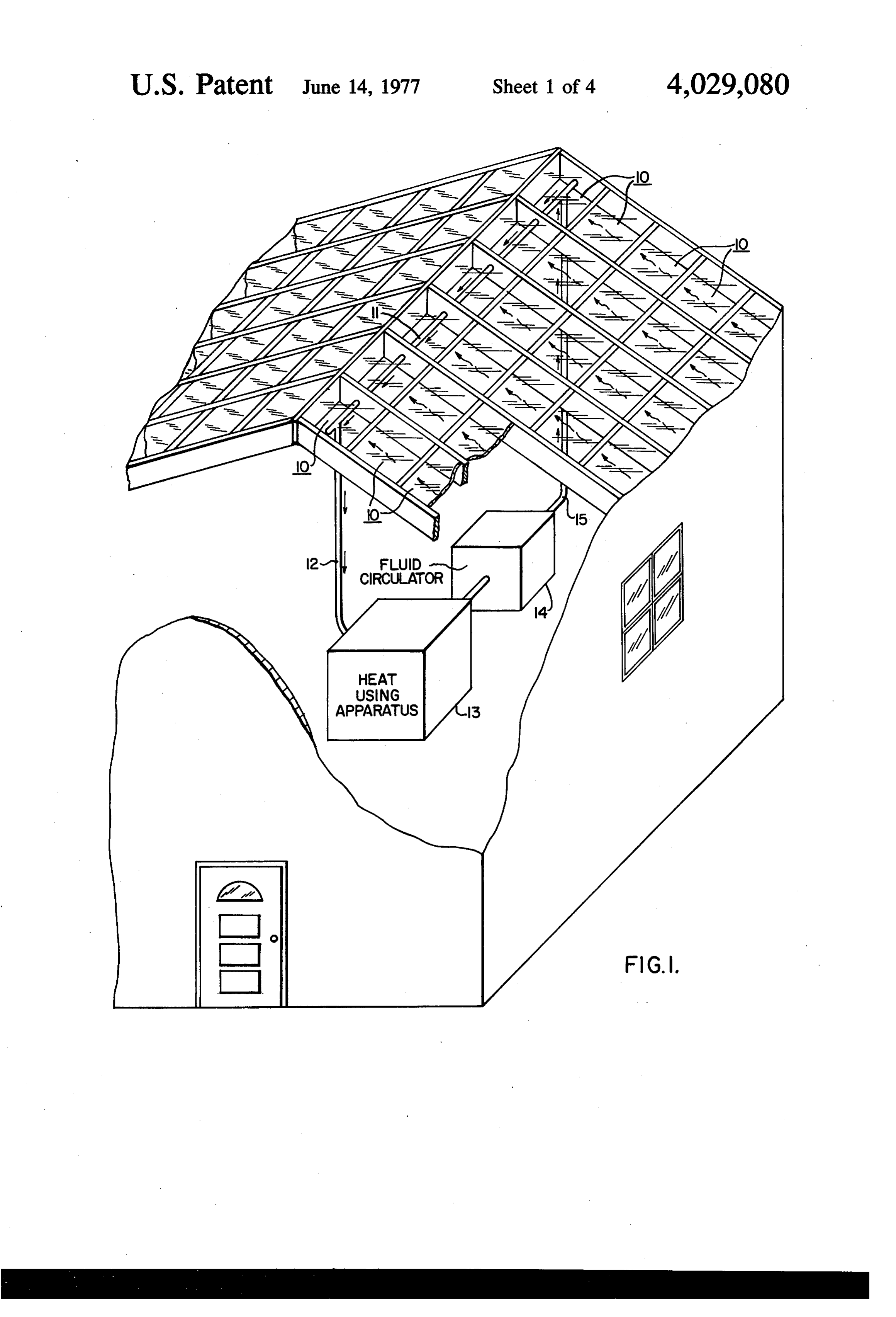
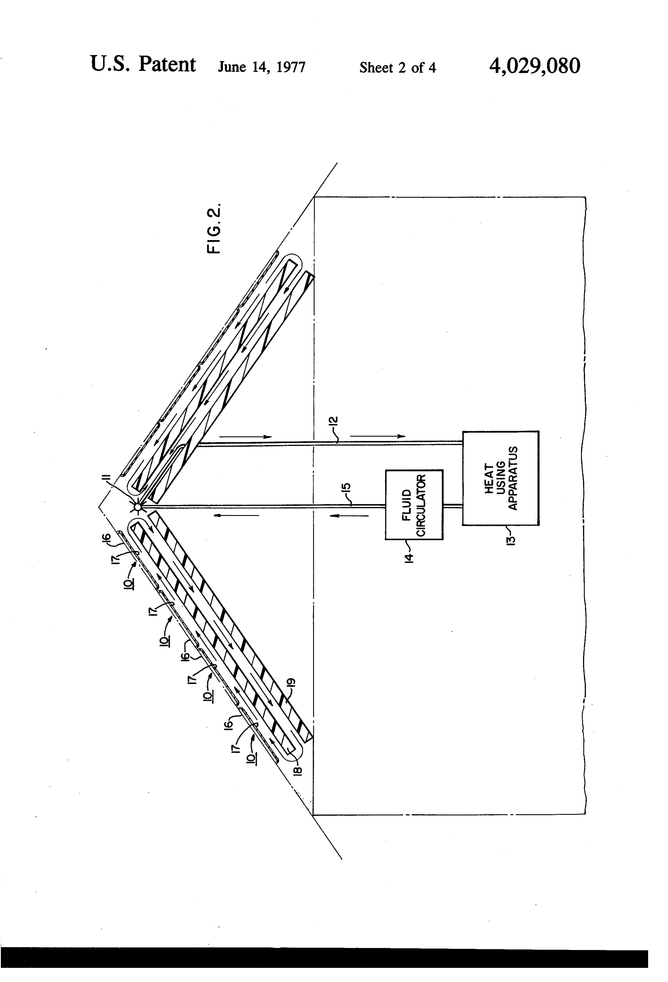
BACKGROUND OF THE INVENTION FIG. 1 shows a cutaway view of a building with ther The present invention relates to thermal collectors of mal collectors of solar energy according to the present solar energy, and more particularly to such collectors invention installed in the roof thereof, and means to that are adapted for installation in the roof structure of deliver heat from the collectors to a heat using appara a building. 10 tus,
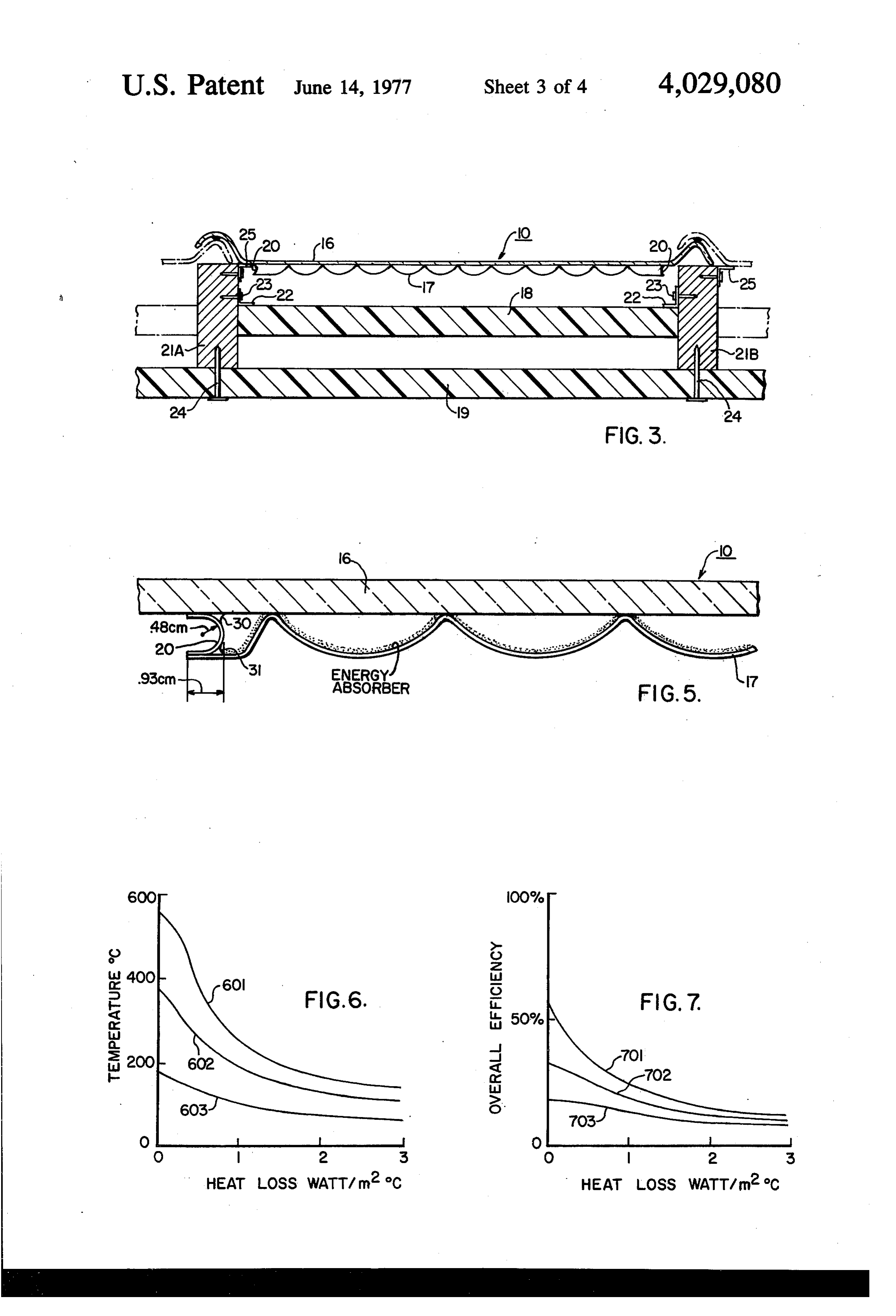
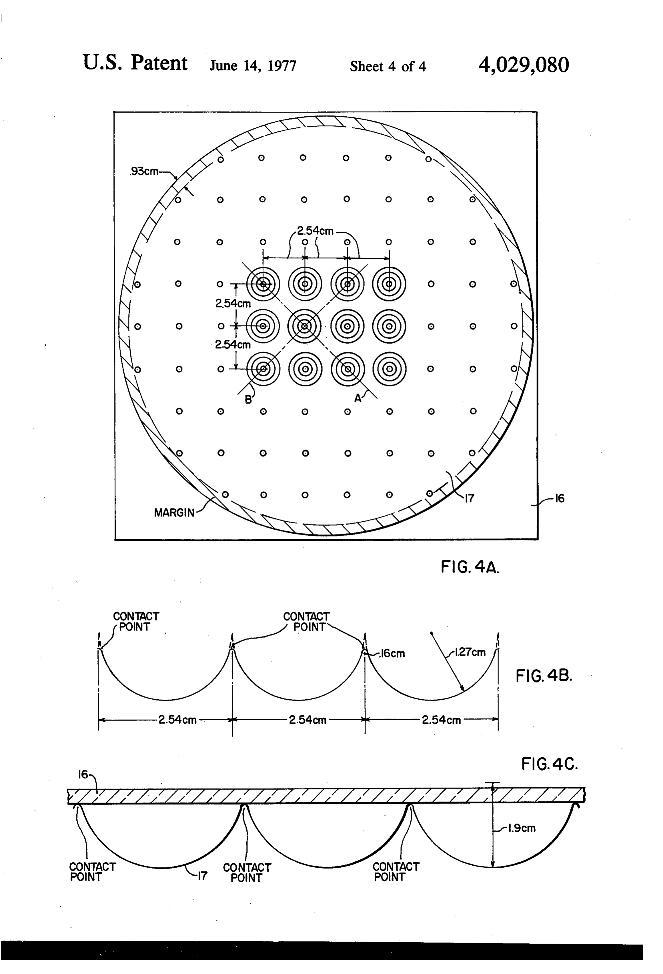
A thermal collector of solar energy collects energy of FIG. 2 shows thermal collectors according to the the sunshine that is incident upon the collector. The present invention as viewed transversely between adja collected energy is transferred as heat to a heat using cent rafters of the roof shown in FIG. 1; apparatus such as a heat pump, a home heating or air FIG. 3 shows a thermal collector according to the conditioning system, or steam generating equipment in 15 present invention as viewed longitudinally of adjacent a power plant. rafters of the roof shown in FIG. 1; Typically, a number of thermal collectors is required FIGS. 4A-4C show details of a backing that is in to collect an amount of energy that satisfies the heat cluded in a thermal collector according to the present input requirement of the heat using apparatus, and invention;
such number usually increases when the heat input 20 FIG. 5 shows details of an assembled thermal collec requirement is increased. To satisfy the heat input re tor according to the present invention; quirement of power plant steam generating apparatus, FIG. 6 graphically illustrates one aspect of the per for example, a large number of collectors is required, formance of a thermal collector according to the pre covering a substantial area on which sunshine is inci sent invention; and dent. To satisfy the heat input requirement of a home 25 FIG. 7 graphically illustrates another aspect of the air conditioning system, as another example, may re performance of a thermal collector according to the quire a number of collectors so great that the area present invention.
occuplied by the collectors exceeds the roof area of the DESCRIPTION OF THE PREFERRED home. The number of collectors is reduced, however, EMBOOMENT by raising the efficiency at which heat is used by the 30 heat using apparatus. Referring to FIG. 1 a portion of the roof structure of Various collector designs have been proposed. In a building is shown. A plurality of thermal collectors of some designs moisture may condense within the collec solar energy is installed in the roof structure shown, tor, limiting the efficiency of collection and diminishing each such collector being indicated by the reference the operating lifetime of collector elements. In other 35 number 10. Each collector 10 is adapted to fit over and designs a medium which delivers heat to the heat using to attach to adjacent rafters, as later described. The apparatus may freeze under various low temperature collectors are adapted to form weatherproofjoints with conditions. Still other designs require extensive modifi another both longitudinally and transversely of the cation of the roof structure in which the collectors are rafters, along the lines shown. Solar radiation is trans installed. In one class of proposed collectors, air may 40 mitted through a translucent window of each collector leak into the collector, corroding collector elements 10, and energy of the transmitted radiation is collected and diminishing the efficiency of collection. (by means not shown) as heat.
There appears to be a need for a thermal collector Between each pair of adjacent rafters, a flow of cool which is adapted to operate at elevated temperatures, ant air passes beneath the associated collectors and to increase the efficiency of the heat using apparatus 45 acquires collected heat. In this instance, heated coolant and thereby to decrease the number of collectors re air passes upwardly between adjacent rafters and gives quired to satisfy the heat demand of such apparatus, up heat to a fluid-filled tube 11, that is positioned near and which is adapted for installation in a roof without the ridge of the roof and runs transversely of the raf. extensive modification of the roof structure. It is desir ters. A heat transfer fluid passes through the tube 11 able to provide such a collector whose operating life 50 and acquires heat from the flows of heated air that pass time and efficiency remain undiminished in the face of upwardly between the pairs of adjacent rafters. Thus, widely changing conditions of climate to which the the heat transfer fluid becomes increasingly hotter as it collector is exposed. flows through the tube 11 in the direction indicated by The description of prior art herein is made on good the arrows.
faith and no representation is made that any prior art 55 Heated fluid passes from an outlet of the tube 11 considered is the best pertaining prior art nor that the through a conduit 12 to a heat using apparatus 13, interpretation placed on it is unrebuttable. which derives heat from the fluid to heat the building, SUMMARY OF THE INVENTION to air condition the building, or to operate a heat pump or the like. A fluid circulator 14 passes cold fluid from
A thermal collector of solar energy includes a ther 60 the heat using apparatus 13 through a conduit 15 to an mally conductive backing which carries an energy inlet of the tube 11, as shown.
absorbing material to absorb energy of solar radiation Typically the thermal collectors are installed to ex that is incident upon the material, and to transfer the tend generally from the eaves (not shown) to the ridge heat of such absorbed energy to the backing. A translu of the roof shown in FIG. 1, in order to deliver as much cent window is disposed in relation to the backing to 65 heat as possible to the heat transfer fluid that flows transmit solar radiation to the energy-absorbing mate through the tube 11. Depending upon factors such as rial. A space between the backing and the window is the geographical location of the building, thermal col hermetically sealed and evacuated to reduce conduc lectors may be installed in the second side of the roof as 7 well as the first, in which case the fluid-filled tube 11 is attached to the backings to improve heat transfer be disposed to acquire heat from air currents on both sides tween the backings and the associated flow of coolant of the roof, or a second fluid-filled tube (not shown) is air, in which the fins are generally parallel to the flow of connected in parallel with the tube 11, between the air. The heat transfer fluid passes through the tube 11 conduits 12 and 15, the purpose of such second tube and carries heat through the conduit 12 to the heat being to acquire heat from the air flows which cool the using apparatus 13, which extracts heat from the heat collectors that are installed in the second side of the transfer fluid. From the apparatus 13 cold fluid passes roof. through a fluid circulator 14 and a conduit 15 to the Each thermal collector 10 is adapted for operation at tube 11, where such cold fluid is reheated. an elevated temperature, as later described. This adap 10 A layer of insulating material 19 is disposed beneath tation permits the heat transfer fluid in the tube 11 to and generally parallel to the insulating layer 18. The reach an elevated temperature before it passes through space between the insulating layers 18 and 19 is a sec the conduit 12 to the heat using apparatus 13. The ond air passageway. Air that has imparted heat to the elevated temperature of the heat transfer fluid im tube 11 is drawn downwardly through the second air proves the efficiency at which the heat using apparatus 15 passageway, in this case by convection. At the bottom 13 uses heat that is collected by the thermal collectors. of the second air passageway, air is drawn into the Such improved efficiency reduces the heat input re lower portion of the first air passageway. Such air then quirements of the heat using apparatus 13. If the heat rises through the first air passageway, where it is re input requirement is satisfied by the thermal collectors heated by heat transfer with the backings of the ther alone, then such a reduced requirement in turn reduces 20 mal collectors, as previously described. It is understood the number of thermal collectors needed. If the heat that such an arrangement of insulating layers, thermal input requirement is greater than the thermal collectors collectors, and air current as described is provided can satisfy when all of the available roof area is used for between each pair of adjacent rafters, to transfer heat installation of the collectors, then the heat using appa from the backings of the associated thermal collectors ratus 13 requires a supplemental heat input (not 25 to the heat transfer fluid that passes through the tube shown) so that the heat collected by the thermal collec 11.
tors and the supplemental heat together satisfy the heat Referring now to FIG. 3, there is shown a thermal input requirement. In that case, the elevated tempera collector 10 as viewed longitudinally of adjacent raf ture of the heat transfer fluid desirably reduces the ters. A ridge is formed on each longitudinal edge of the amount of supplemental heat that is required. 30 glass cover plate 16 to permit overlap of the cover The configuration of the ridge and rafter components plates of thermal collectors that are installed adjacent of the roof structure shown in FIG. 1 is conventional, to the thermal collector 10, as shown by the dotted with the rafters extending downwardly from the ridge lines. Such overlap assists in forming a weatherproof to the eaves (not shown). As will be seen the rafters longitudinal joint between the adjacent thermal collec and ridge are not visible from the exterior of the build 35 tors. The joints may be rendered further weatherproof . ing as shown in FIG. 1, such components being shown by the application of various rubber or plastic sealants. in that figure for clarity of illustration. Similar joints are formed between those thermal collec Referring now to FIG. 2 a view of the roof structure tors that are installed above and below the thermal transverse of the rafters indicates a plurality of thermal collector 10, between the adjacent rafters shown in collectors disposed between a pair of adjacent rafters 40 FG, 3.
(not shown) and extending upwardly from the eaves With further reference to FIG. 3, a continuous rim 20 toward the ridge, each collector being indicated by the joins the backing 17 to the cover plate 16 and hermeti reference numeral 10. The collectors join one and cally seals an evacuated space that is bounded by the another at weatherproof joints at the points indicated. cover plate 16, the backing 17 and the rim 20. Evacua Each collector 10 includes a translucent window 16, in 45 tion of such space greatly reduces loss of heat from the this case a square glass cover plate approximately 1.2 backing 17 to the cover plate 16, which loss otherwise m. by 1.2 m., which transmits solar radiation to a heat would result from conductive and convective heat conductive backing 17, in this case steel, which carries transfer by air entrapped within the space. Elimination on its upper surface an energy-absorbing material (not of such convective and conductive losses raises the shown) that absorbs as heat a substantial portion of the 50 operating temperature of the upper surface of the energy of the transmitted radiation. The heat of such backing 17, which in turn raises the temperature of the absorbed energy flows through the heat conductive heat transfer fluid as such fluid flows through the con backing 17 to its lower surface. duit 12 to deliver heat to the heat using apparatus 13 A layer insulating material 18 is disposed beneath the (see FIG. 1). In accordance with thermodynamic prin backings of the thermal collectors to form a first air 55 ciples, the efficiency at which the heat using apparatus passageway between the backings and the insulating 13 uses heat that is delivered by the heat transfer fluid layer. A flow of coolant air passes through the first air normally improves as the temperature of the heat trans passageway in heat transfer relation with the lower fer fluid increases. In particular, if the temperature of surfaces of the backings, whereby the flow of coolant the heat transfer fluid is represented by T., (Kelvin) air acquires heat from the backings. In this case the 60 and the heat using apparatus 13 exhausts heat at a flow of coolant air passes upwardly through the first air temperature of T, (Kelvin), then the amount of work passageway. At the top of the first passageway heated W that is delivered by the apparatus 13 from an coolant air imparts heat to the fluid-filled tube 11, as amount of heat O that is derived from the heat transfer previously described with reference to FIG. 1. The fluid at temperature T is given by: W/O s to 1 cross section of the tube 11 that is shown in FIG. 2 65 T/T. In the relationship above, the efficiency of the reveals a plurality offins which are affixed to the tube heat using apparatus 13, namely Wh/O, is less than or 11 to improve heat exchange between the air currents equal to an upper limit that increases when the temper (see FIG. 1) and the heat transfer fluid. This may be ture T increases with respect to the temperature T.
Page 8scan →
Thus, the efficiency of the heat using apparatus 13 imately 2.54 cm for a relatively thin backing 17 of normally increases when the temperature of the heat approximately 0.037 cm. If the backing 17 is thicker transfer fluid, T., increases. As previously discussed, than 0.037 cm, the distance between neighboring pro such improved efficiency either reduces the number of jections may be increased, and conversely the distance thermal collectors that is required to satisfy the heat 5 between neighboring projections may be descreased if input requirement of the heat using apparatus 13, or it the thickness of the backing 17 is less than 0.037 cm. reduces the amount of supplemental heat that may be The dots in FIG. 4A indicate that the pattern of projec required by the apparatus 13 in the event that the heat tions generally extends over the entire backing 17, input requirement cannot be satisfied fully by the total except that the outer margin of the backing, shown by ity of thermal collectors. 10 the shaded portion within the periphery, is generally The backing 17 is disposed beneath the glass cover flat and has no projections formed therein. The margin plate 16 and between adjacent rafters 21A and 21B. is used for installation of the rim 20 (see FIG. 3), as The backing 17 is formed from a sheet of thermally hereinafter described.
conductive material, in this case steel. For purposes of FIG. 4B shows a section of the backing 17 that is limiting the weight of the assembly comprising the 15 perpendicular to the cover plate 16 (not shown) and coverplate 16, the backing 17 and the rim 20, the passes through the line A that is shown in FIG. 4A. The weight of the backing 17 is limited by forming the back section generally reveals a series of semicircles, each ing from relatively thin sheet steel, in this case having a having a radius of curvature of 1.27 cm as shown. The thickness of 0.037 cm. Thus, the aforementioned as points at which the backing 17 contacts the cover plate sembly, with a 1.2 m. by 1.2 m. glass cover plate 16 that 20 16 are indicated. in the vicinity of a contact point, the is approximately 0.93 cm thick, weighs about 45 kg. radius of curvature of the section changes from 1.27 The limited weight of the backing 17 correspondingly cm to 0.16 cm. The dotted lines in the vicinity of a limits the total mass of the backing, and thus limits the contact point are extensions of the semicircles that thermal inertia of the backing. The limited thermal form the major portions of the section, and are in inertia of the backing 17 permits the backing to re 25 cluded for purposes of illustration. Because the loca spond quickly to changing sunlight conditions. For tions of the projections of the backing 17 form a grid example, when the sunlight reappears after a duration pattern, as indicated in FIG. 4A, it is evident that a of absence, as on a cloudy day, the temperature at the section of the backing 17 that is perpendicular to the lower surface of a thick backing increases more slowly cover plate 16 (not shown) and passes through the line than the temperature at the lower surface of a relatively 30 B shown in FIG. 4A, reveals a pattern of semicircles thin backing, due to the lower thermal inertia that is and contact points of the radius of curvature indicated associated with the relatively thin backing. Conse in FIG. 4B.
quently, an increase of the temperature of the heat shown FIG. 4C shows the section of the backing 17 that is transfer fluid as such fluid flows through the conduit 12 in FIG. 4B and further includes a section of a to the heat using apparatus 13 (see FIG. 1), in response 35 portion of the glass cover plate 16. It is seen that the to the reappearance of the sunshine, is desirably more projections of the backing 17 extend upwardly to rapid for a relatively thin backing than for a thick back contact the cover plate 16. The area of contact be . tween the cover plate 16 and a projection of the back Because the thermal collector 10 is evacuated and ing 17 is limited by the reduced radius of curvature of hermetically sealed, there is a pressure differential 40 a projection near the contact point (see FIG. 4B). As between the upper and lower surfaces of the backing the thickness of the cover plate 16 is 0.93 cm, the 17, which pressure differential tends to push the back distance from the top of the cover plate 16 to the low ing 17 toward the cover plate 16, especially when the est extremity of the backing 17 is approximately 1.9 cm backing is relatively thin. To prevent such structural 45 as shown.
collapse of the backing 17 due to the pressure differen Because each projection is a path through which tial thereacross, a plurality or projections is formed leakage heat flows from the overall body of the backing integrally in the backing, each projection extending 17 to the cover plate 16, the total flow of leakage heat from the overall surface of the backing to contact the through all of the projections of the backing 17 is desir lower surface of the coverplate 16. A plurality of such ably much smaller than the flow of collected heat projections is shown in FIG. 3. 50 through the backing 17 to its lower surface (see FIG.2) FIG. 4A shows the backing 17 as viewed from di where such heat is acquired by the flow of coolant air. rectly above the cover plate 16 wherein each set of Iferssuch is not the case, the total leakage heat flow low the operating temperature of the upper surface of concentric circles is associated with a projection of the backing 17. Each circle is a cross-section of a projec 55 the backing 17, which in turn lowers the temperature of tion that is taken parallel to the cover plate 16. Because the heat transfer fluid that delivers heat to the heat a projection generally tapers inwardly as it extends using apparatus 13 (see FIG. 1), and the efficiency of from the overall surface of the backing 17 to the cover the apparatus 13 normally is reduced, as heretofore plate 16, sections of a single projection are concentric explained. The small radius of curvature of a contact circles of decreasing diameter as the sections are taken 60 point, in this case 0.16 cm, reduces the contact area closer to the cover plate 16. Thus, each set of concen between a projection and the cover plate 16. The re tric circles corresponds to sections of a single projec duced contact area reduces the flow of leakage heat tion that are parallel to the cover plate 16 as taken at thethrough the projection to the cover plate. In addition, various distances from the cover plate. When viewed relatively thin backing 17, in this case 0.037 cm, from above the backing 17, the projections are located 65 reduces the thermal conductivity of a projection, which in a grid pattern, wherein the distance between the inprojection.
turn reduces the flow of leakage heat through the
A calculation of the thermal conductance center of the concentric circular cross-sections of a given projection and the center of the concentric circu of a projection of the backing 17 appears in Appendix lar cross-sections of a neighboring projection is approx 1, and it is concluded from such calculation that the 9 total leakage heat flow through the projections of the efficients of expansion. When the temperatures of the backing 17 to the cover plate 16 is negligible in com cover plate 16 and the backing 17 change during the parison with a typical flow of collected heat through course of operation of the thermal collector 10, the the backing 17 to its lower surface. difference between such temperature coefficients With reference again to FIG. 3 the layer of insulating causes lateral displacement of the cover plate relative material 18 reduces heat losses from the current of air to the backing, thereby deflecting the mechanically that passes between the backing 17 and the layer 18 compliant rim 20. While a rigid non-yielding rim could (see FIG. 2), and from the backing 17. The insulating break as opposed to deflecting at such times, the flexi layer 18 is disposed generally parallel to the backing 17 ble rim 20 deflects, i.e., changes its radius of curvature, and is supported in such position by the rafters 21A and O to permit such lateral displacement withoutbreaking. It 21B. A plurality of tabs 22 are attached to the insulat is understood that breakage of the rim 20 permits air ing layer 13 at longitudinally spaced intervals, to permit and moisture to enter the otherwise evacuated space attachment of the layer 18 to the rafters. A nail 23, or within the thermal collector 10. Air in such space re a similar fastener, extends through each tab 22 to its duces the operating temperature of the backing 17, associated rafter, to fasten the insulating layer 18 to the 15 which in turn reduces the temperature of the heat rafters 21A and 21B. transfer fluid as it flows through the conduit 12 (see The insulating layer 19 is disposed beneath and gen FIG. 1) to the heat using apparatus 13. Both air and erally parallel to the layer 18. The insulating layer 19 moisture in such space may corrode the elements of the reduces heat loss from the air current that passes be thermal selector 10 reducing its operating efficiency tween the layers 8 and 19 (see FIG. 2). The insulating 20 and lifetime, as hereinafter discussed. layer 19 is affixed to the lower surfaces of the rafters The rim 20 is a path through which a flow of leakage 21A and 21 B by a plurality of nails 24. Attachment tabs heat passes from the backing i7 to the cover plate 16. 25 are affixed to the cover plate 16 and screws or nails If such flow of leakage heat is not small in relation to project through the attachment tab to an adjacent raf the overall flow of collected heat through the backing ter to hold the collector in place. 25 17 to its lower surface, then the operating temperature With reference now to FIG. 5 the rim 20 is joined of the upper surface of the backing is reduced by the with the glass cover plate 16 by an airtight seal 30, and heat flow through the rim, and in turn the temperature with the backing 17 by an airtight seal 31. The seal 30 of the heat transfer fluid at the outlet of the tube 11 is preferably frit seal that is formed by applying a pow (see FIG. 1) is reduced. As heretofore explained such dered glass in a paint solution to the area of contact 30 temperature reductions normally reduce the efficiency between the rim 20 and the cover plate 16. With such at which the apparatus 13 uses heat. The thermal con a solution applied, the assembly of the rim 20 and the ductance of the rim 20 is limited by the reduced thick cover plate 16 is heated until the powdered glass melts. ness of the rim, in this case 0.00254 cm. A calculation The melted glass is permitted to solidify, whereupon of the thermal conductance of the rim 20 appears in the airtight seal 30 joins the rim 20 along its upper edge 35 Appendix 2. The flow of leakage heat through the rim to the glass cover plate 6. Along its lower edge the rim 20 is considered when the performance of the collector 20, in this case of steel, preferably is soldered to the 10 is evaluated, as hereinafter discussed. The heat flow steel backing 17, thereby forming the airtight seal 31. through the rim 20 is reduced further when the rim is With reference again to FIG. 4A, the solder seal 31 formed from a steel of relatively low thermal conduc continuously joins the rim 20 with the backing 17 along 40 tivity, such as stainless steel. the margin of the backing. As previously explained the With further reference to FIG. 5, the upper surface of margin of the backing 17 as shown in FIG. 4A is flat, the backing 17 carries an energy-absorbing material. the projections of the backing 17 being formed within Solar radiation is transmitted through the cover plate the margin. Thus the margin of the backing 17 is 16 to the energy-absorbing material, which absorbs as adapted to be joined with the rim 20 by the solder seal 45 heat a substantial portion of the energy of the transmit 31, which is disposed between the rim 20 and the mar ted radiation. Such heat passes through the energy gin. The rim 20 is itself continuous, and a section of the absorbing material to the upper surface of the backing rim 20 that is parallel to the cover plate A6 is a full 17, and thereafter the heat flows through the backing circle of diameter somewhat smaller than the diameter 17 to its lower surface, where the heat is acquired by a of the backing 17 (see FIG. 4A). The frit seal 31 con 50 flow of coolant air (see FIG. 2). The majority of the tinuously joins the upper portion of the rim 20 (see energy of the transmitted solar radiation is carried by FIG. 5) with the cover plate 16. During manufacture, radiation of wavelengths between 0 and 1.4 micron. At the space bounded by the cover plate 16, the backing wavelengths greater than approximately 1.4 micron, 17 and the rim 20 is evacuated after the seals 30 and 31 the energy level of solar radiation is relatively low. An are formed, and the airtight seals 30 and 31 thereafter 55 ideal energy-absorbing material absorbs all of the en maintain the vacuum. ergy of solar radiation of wavelengh less than 1.4 mi With reference again to FIG. 5, the rim 20 preferably cron (an absorptivity of 1.0 over such wavelength is relatively thin, in this case, the thickness of the rim range), and absorbs none of the energy of solar radia 20 is approximately 0.00254 cm. The cross section of tion of wavelength greater than 1.4 micron (an abosr the rim 20 that is shown in FIG. 5 includes a semicircu 60 ptivity of 0.0 over such wavelength range). Since it lar portion of radius 0.48 cm. The width of the margin absorbs none of the energy of radiation of wavelength of the backing 17, where the rim 20 is joined with the greater then 1.4 micron, the ideal energy-absorbing backing, is typically 0.93 cm as shown (see also FIG. material also reradiates none of the absorbed energy at 4A). Similarly, the portion of the rim 20 that is joined those wavelengths, and such zero reradiation permits with the cover plate 6 is 0.93 cm as shown. 65 the upper surface of the backing 17 to operate at desir An important feature of the rim 20 is its mechanical ably elevated temperatures, whereby the efficiency of compliance. The glass cover plate 16 and the steel the heat using apparatus 13 (see FIG. i.) normally is backing 17 typically possess different temperature co improved.
Page 10scan →
Typical energy-absorbing materials are nickel oxide thermal collector 10 which includes an ideal energy and chromium oxide. Nickel oxide or chromium oxide absorbing material, a curve 702 relates to a thermal preferably is electrolytically deposited on the backing collector which includes the (0.9, 0.01) material, and a 17 after the projections are formed therein, and before curve 703 relates to a collector including the (0.9, 0.1) the rim 20 is joined with the backing 17 by the solder 5 material. A reduction of the heat losses from 4.0 (not seal 3. An actual energy-absorbing material such as shown) to 1.0 by evacuation of the thermal collector nickel oxide or chromium oxide usually absorbs less approximately raises the best efficiency from 15% to than all of the energy of solar radiation at wavelengths 27%, for a collector which includes an ideal energy less than 1.4 micron, and reradiates some of the ab absorbing material (line 701). A similar reduction of sorbed energy at wavelengths greater than 1.4 micron. O the heat losses improves the best efficiency of the col Such differences between ideal and actual energy lector which includes the (0.9, 0.01) material (line absorbing materials affect the operating temperature of 702) and of the collector which includes the (0.9, 0.1) the backing 17 and the efficiency of the heat using material (line 703), but the amount of improvement apparatus 13 (see FIG. 1) as hereinafter described. decreases as the longer wavelength absorbtivity of the Referring to FIG. 6 the best operating temperature 15 energy-absorbing material increases. (centigrade degree) of the thermal collector 10 is The performance of the thermal collector 10 which graphically shown on the vertical axis in relation to the includes nickel oxide or chromium oxide as the energy total heat loss from the collector, shown on the hori absorbing material may be estimated from the curve zontal axis in watts per square meter per centigrade 603 of FIG. 6 and the curve 703 of FIG. 7. Since the degree. The best operating temperature is that temper combined heat loss through the rim 20 and through the ature which maximizes the overall efficiency of the insulating layer 18 is approximately 1.0 (see Appendix thermal collector 10 and the heat using apparatus 13, 2) the best operating temperature of the collector is (see FIG. 1). The total heat loss is the sum of the heat about 150 C and the corresponding best efficiency is losses through the rim 20 and the projections of the approximately 20%. On a bright sunny day the energy backing 17 (see FIG. 5) and from the lower surface of 25 level of solar radiation is about 700 watts per square the backing 17 through the insulating layer 18 (see meter. If the thermal collectors and the heat using FIG. 3). The heat loss through the projections of the apparatus 13 (see FIG. 1) operate at the best tempera backing 17, however, is neglected (see Appendix 1). A ture and efficiency on such a day, then the temperature curve 601 relates to a thermal collector 10 which uti of the heat transfer fluid is about 150°C at the outlet of lizes an ideal enery-absorbing material as heretofore 30 the tube 11, and the energy output of the heat using described with reference to FIG. 5. A curve 602 relates apparatus 13 is approximately 140 watts for each to a thermal collector 10 which utilizes an energy square meter of the surface area of the transparent absorbing material that absorbs 90% of the energy of windows of the thermal collectors that are installed in radiation of wavelength below approximately 1.4 mi the roof of the building shown in FIG. 1. cron, while it absorbs only 1% of the energy of radia 35 With reference to FIG. 6 the vertical separation of tion of wavelength greater than 1.4 micron, and thus the curves 601, 602 and 603 at 1.0 heat loss show that reradiates relatively little absorbed energy at such the best operating temperature of the thermal collector wavelengths. For brevity the energy-absorbing material 10 correspondingly increases when reradiation of ab is referred to as the (0.9, 0.01) material. A curve 602 sorbed energy at longer wavelengths (1.4 micron and relates to a thermal collector 10 that includes an ener 40 greater) decreases. Because a significant part of such gyabsorbing material that absorbs 90% of the energy of energy is radiated from the backing 17 upwardly radiation less than approximately 1.4 micron, while it through the cover plate 16 (see FIG. 2), a coating may absorbs 10% of the energy of radiation of wavelength be applied to the inner surface of the cover plate 16 to greater than 1.4 micron, for brevity the (0.9, 0.1) mate reflect longer wavelength radiation back to the backing rial. The (0.9, 0.1) material thus reradiates more ab 45 17, and thereby to raise the best operating temperature sorbed energy at higher wavelengths than the (0.9, of the thermal collector. Such a coating, however, must 0.01) material. effectively transmit lower wavelength radiation to the With respect to the curve 601, elimination of con backing 17, as the energy of solar radiation is heavily ductive and convective heat losses due to air that is concentrated at such lower wavelengths. Materials that entrapped within the thermal collector 10, changes the SO are suitable for application to the inner surface to the heat loss on the horizontal axis from approximately 4.0 cover plate 16 are gold, tin oxide and indium oxide. (not shown) to approximately 1.0. The best operating When such materials are used, they are evaporated temperature correspondingly increases about 150°C to onto the cover plate 16.
300 C. Reduction of the heat loss from 4.0 to 1.0 also The aforementioned materials that are applied to the improves the best operating temperature for the collec 55 backing 17 and possibly to the cover plate 16 typically tors using the (0.9, 0.01) and the (0.9, 0.1) energy are subject to air and moisture contamination and pos absorbing materials, curves 602 and 603 respectively, sibly to corrosion, which contamination and corrosion but the amount of improvement of the operating tem reduce the lifetime of the materials and diminish the perature decreases as the longer wavelength absorb effectiveness of the thermal collector. Evacuation of tivity of the energy-absorbing material increases. 60 the space bounded by the cover plate 16, the backing Referring to FIG. 7 the best percentage overall effi 17 and the rim 20 not only desirably reduces heat losses ciency of the thermal collector 10 and the heat using due to air that otherwise would be entrapped in such apparatus 13 is graphically shown on the vertical axis, space, but additionally extends the lifetime of the mate in relation to the heat losses from the collector shown rials and thereby maintains the collector in an effective on the horizontal axis in units of watts per square meter 65 operating condition.
percentigrade degree. The best overall efficiency is the The best operating temperature and the correspond efficiency that corresponds to the best operating tem ing best overall efficiency of the thermal collecotr 10 perature, as shown in FIG. 6. A curve 701 relates to a and the heat using apparatus 13 are improved when an 11 energy-absorbing material of considerably reduced Rim Loss longer wavelength absorbtivity is substituted for nickel oxide or chromium oxide, as described in Ser. No. For a rim width W of 1.27 cm and thickness 8, speci 552,834, "An Improved Solar Electric Power Plant and fied below, and a thermal conductivity k of most steels, an Improved Thermal Collector of Solar Energy for 0.12 cal/C cm sec, use Q= kL8/W where L, the perim Use Therein", by Roger W. Warren. eter of the collector, is 16', and find Q = 1.9 x 10' X 5 Although the present invention is disclosed in a spe watt?m C. Now since the rim 20 doesn't afford me cific embodiment thereof, it is understood that various chanical support for the backing 17 but only makes a modifications, changes and substitutions can be made vacuum seal, values of 8 as low as 1 mill give the rim the without departing from the spirit and scope of the in 10 desired flexibility. Using this value of 8 Q = 0.49 watt? vention. C, or expressed in the same area units, Q/A = 0.33
Appendix 1
watt?m C. Since this is a perimeter-related loss, larger collectors have a lower value of O/A.
The heat loss through a projection is composed of claim:
two parts, along the walls of the projection and at its 15 1. A thermal collector of solar energy adapted for contact with the glass cover 16. The first part can be high a temperature operation, comprising, relatively thin thermally conductive backing having estimated by considering the wall of the projection to be a cylindrical tube. Its conductance is given by Q = relatively low thermal inertia and being disposed kat Döll. 8 is approximately the thickness of the backing 20 for transferring collected heat to an external cool 17 which is taken to be 0.037 cm. l is about 1 cm and D ant, has about the same value. Setting k = 0.12 cal/C cm a translucent and relatively stiff window to transmit sec, the conductivity of steel, Q = 0.061 watt/C. solar radiation,
The second part of the projection heat loss is the an energy-absorbing material carried by said backing conductance of the contact. The first contact is nor to absorb energy of solar radiation and transfer the mally at a microscopic sharp corner. If the pressure at 25 heat of such absorbed energy to said backing, this point increases the stress eventually exceeds the first means for supporting said window relative to elastic limit of the weakest material at the contact caus said backing generally about the window periphery ing its plastic deformation. The deformation continues to expose said energy-absorbing material to solar as the pressure increases so that the area of the contact, 30 radiation that is transmitted by said window, means A, is continually given by A = FIP, where Fis the force for sealing an evacuated space between said win applied, and P is the yield strength of the weakest dow and said backing, and second means for sup material. Using this description of the contact the ther porting said window relative to said backing over at mal conductance of the contact is given roughly by Oc least one area within the window periphery so as to as rk = V FlarPk or Q = VP/PX VkfarC be 35 ferentials resulting strengthen said thin backing against pressure dif cause F = PA/C, where P is atmospheric pressure and from evacuation while limiting . C is the concentration of projections in cm. Using for leakage of absorbed heat to said window to a rela k the usual value for mild steel, for P, its yield point of tively low value.
about 25 kg/mm, and for C the value corresponding to the2.weight A thermal collector according to claim 1 wherein a 10 cm separation between projections i.e. 0.01 cm, 40 response ofofthethecollectorcollector is reduced and the thermal is improved by reducing the
Q = 0.057 watt? C. Now the heat flow path in the thickness of said backing to an extent that said backing glass cover 16 at the contact point is similar to that in is subject to structural collapse due to a pressure differ the projection itself, and so the conductance in the ential thereacross, and at least one projection is formed glass is nearly the same as in the projection except for the greatly reduced (s.50 times) conductivity of glass. 45 in said backing to extend from the overall surface of said backing to said window to prevent such collapse.
The glass conductance is estimated to be Q s 0.001 watt? C. Finally, the overall projection conductance in 3.theAroof thermal collector of solar energy for installation structure of a building, and adapted for high
Op is a combination of Ow, Oc and Q and is limited temperature operation, comprising, and roughly equal to.Q. s 0.001 watt? C. Put in area a translucent and relatively stiff cover plate to trans units, this conductance is given by Q/A = 0.1 watt?m 50 mit solar radiation, said cover plate being adapted C, a completely negligible quantity. to fit over adjacent rafters of the roof, APPENDIX 2 a relatively thin thermally conductive backing having relatively low thermal inertia and being disposed
The remaining important heat loss paths are two: for transferring collected heat to an external cool conduction through the rim 20, and through the insula 55 ant, tion 18. These two losses are estimated for the 1.2 m by an energy-absorbing material carried by said backing 1.2 munit and for a reasonable choice of other parame to absorb energy of solar radiation and transfer the ters. heat of such absorbed energy to said backing, INSULATION LOSS first means for supporting said backing relative to 60 said cover plate generally about the cover plate
For a 10 cm thick blanket of rock wool insulation periphery to expose said energy-absorbing material with a conductivity k = 0.03 BTU/hr ft F, use the to solar radiation that is transmitted by said cover formula Q = kA/6, and find a heat conductance given plate, means for hermetically sealing an evacuated by Q/A = 0.51 watt?m C. The actual heat loss is likely space between said backing and said cover plate, to be considerably less than this because the air above and second means for supporting said cover plate the insulating blanket will itself be a fair insulator. This relative to said backing over at least one area is because it is heated from above, and therefore, is not within the cover plate periphery so as to strengthen likely to exhibit serious convective instabilities. said thin backing against pressure differentials re 12 sulting from evacuation while limiting leakage of an energy-absorbing material carried by said backing absorbed heat to said cover plate to a relatively low to absorb energy of solar radiation and transfer the value. heat of such absorbed energy to said backing, 4. A thermal collector according to claim 3 wherein first means for supporting said cover plate relative to the weight of the collector is reduced and the thermal said backing generally about the cover plate pe response of the collector is improved by reducing the riphery to dispose said backing between adjacent thickness of said backing to an extent that said backing rafters and beneath said cover plate, whereby said energy-absorbing material is exposed to solar radi is subject to structural collapse due to a pressure differ ation that is transmitted by said cover plate, means ential thereacross, and at least one projection is formed 10 for hermetically sealing an evacuated space be in said backing to extend from the overall surface of tween said backing and said cover plate, said backing to said cover plate to prevent such col means for transferring heat from said backing to the lapse. heat using apparatus, and second means for sup 5. A thermal collector according to claim 3 wherein porting said window relative to said backing over at said cover plate is a square glass window. 15 least one area within the window periphery so as to 6. A thermal collector according to claim 5 wherein strengthen said thin backing against pressure dif the periphery of said backing is a circle of diameter less ferentials resulting from evacuation while limiting than the separation between opposed sides of adjacent leakage of absorbed heat to said window to a rela rafters, whereby said backing is received by the space 20 12.tively low value.
Apparatus according to claim 11 wherein the between adjacent rafters. weight of the apparatus is reduced and the thermal 7. A thermal collector according to claim 6 wherein response of the apparatus is improved by reducing the said means for supporting and hermetically sealing thickness of said backing to an extent that said backing includes a continuous rim having a first portion that is is subject to structural collapse due to a pressure differ continuously joined with said backing, and a second 25 ential thereacross, and at least one projection is formed portion that is continuously joined with said cover in said backing to extend from the overall surface of plate. said backing to said cover plate to prevent such col 8. A thermal collector according to claim 7 wherein lapse.
the thickness of said rim is reduced to an extent that a 30 13. Apparatus according to claim 11 wherein said flow of heat through said rim from said backing to said heat a transferring means include, layer of insulating material disposed beneath said cover plate, is substantially less than the flow of heat backing to form a first passageway between said from said energy-absorbing material to said backing. layer and said backing, and 9. A thermal collector according to claim 3 wherein means to pass aflow of heat transfer fluid through the said supporting sealing means is mechanically compli 35 first passageway, such flow being in heat transfer ant, to permit said cover plate to move laterally with relation with said backing.
respect to said backing, due to a difference between the 14. Apparatus according to claim 13 wherein said temperature coefficients of expansion of said cover heat transferring means further include, plate and said backing, without breakage of said sup 40 a plurality offins attached to said backing to improve porting and sealing means, which breakage would per heat transfer between said backing and the flow of heat transfer fluid.
mit air to enter the collector and reduce its operating 15. Apparatus according to claim 11 wherein said temperature. heat transferring means include, 10. A thermal collector according to claim 3 wherein a first layer of insulating material disposed beneath said first supporting means comprises a material of low 45 said backing, and extending laterally between adja thermal conductance, whereby a flow of leakage heat cent rafters, said first layer being spaced from said through said connecting means from said backing to backing to form a first air passageway, said cover plate is substantially less than the flow of a second layer of insulating material disposed be heat from said energy-absorbing material to said back neath said first layer and extending laterally be ling. 50 tween adjacent rafters, said second layer being 11. Apparatus for collecting solar energy and deliver spaced from said first layer to form a second air ing the collected energy to a heat using apparatus, said passageway, collecting apparatus being adapted for installation be a circulating current of air convected upwardly tween adjacent rafters of a roof, comprising, through the first passageway and downwardly a translucent cover plate to transmit sunlight, said 55 through the second passageway, said current being cover plate being adapted to fit over adjacent raf in heat transfer relation with said backing as it passes through the first passageway, and ters, means for extracting heat from said air current as it a relatively thin backing of thermally conductive emanates from the first passageway and delivering material adapted to be disposed beneath said cover 60 the extracted heat to the heat using apparatus. plate and between adjacent rafters,
Provenance
- Collection
- Patents citing this work
- Pages
- 12
- Method
- pdftotext (the PDF's own text layer) + pdftoppm 300dpi page scans
- Patent office record
- patents.google.com →
- Source
- Google Patents citing-documents table
- Assignee
- Westinghouse Electric Corporation
- Published
- 1977-06-14
- Transcribed from
- patentimages.storage.googleapis.com →