

patent · US4033118A
Mass flow solar energy receiver
5 July 1977
Text
Page 1scan →
United States Patent (19)
Powell
(54) mass flow solar energy receiver
(76) Inventor: William R. Powell, 10403 May Wind Court, Columbia, Md. 21044
52) U.S. C. ........................... 60.641; 1261270
United states patents
294, 17 2/1884 Calver ............................... 126/271 l,66,473 3/1928 Goddard et al. .................. 126/271 1951,403 3/1934 Goddard ............................ 126/271
Primary Examiner-Allen M. Ostrager
Attorney, Agent, or Firm-Kenneth E. Darnell
A receiver for collecting solar energy at high tempera tures with low reradiation losses, the invention com prises in a preferred embodiment an insulated cavity absorber wherein a temperature gradient exists from the receiving end of the absorber toward the closed end thereof. The closed end exists at a higher temperature than the receiving end due to the cooling effect of a flow of fluid directed into contact with the walls of the absorber from the receiving end toward the closed end, the fluid being additionally utilized to extract heat from the absorber for utilization thereof
18 Claims, 6 Drawing Figures
Drawings
Page 2drawing sheetscan →
Page 3drawing sheetscan →
Page 4drawing sheetscan →
Page 5drawing sheetscan →
Page 6scan →
The present energy receiving apparatus preferably
MASS FLOW SOLAR ENERGY RECEIVER takes the form of either a solar energy absorber or
Background of the invention
energy emitter. The apparatus comprises a hollow member having an open entrance end and a closed,
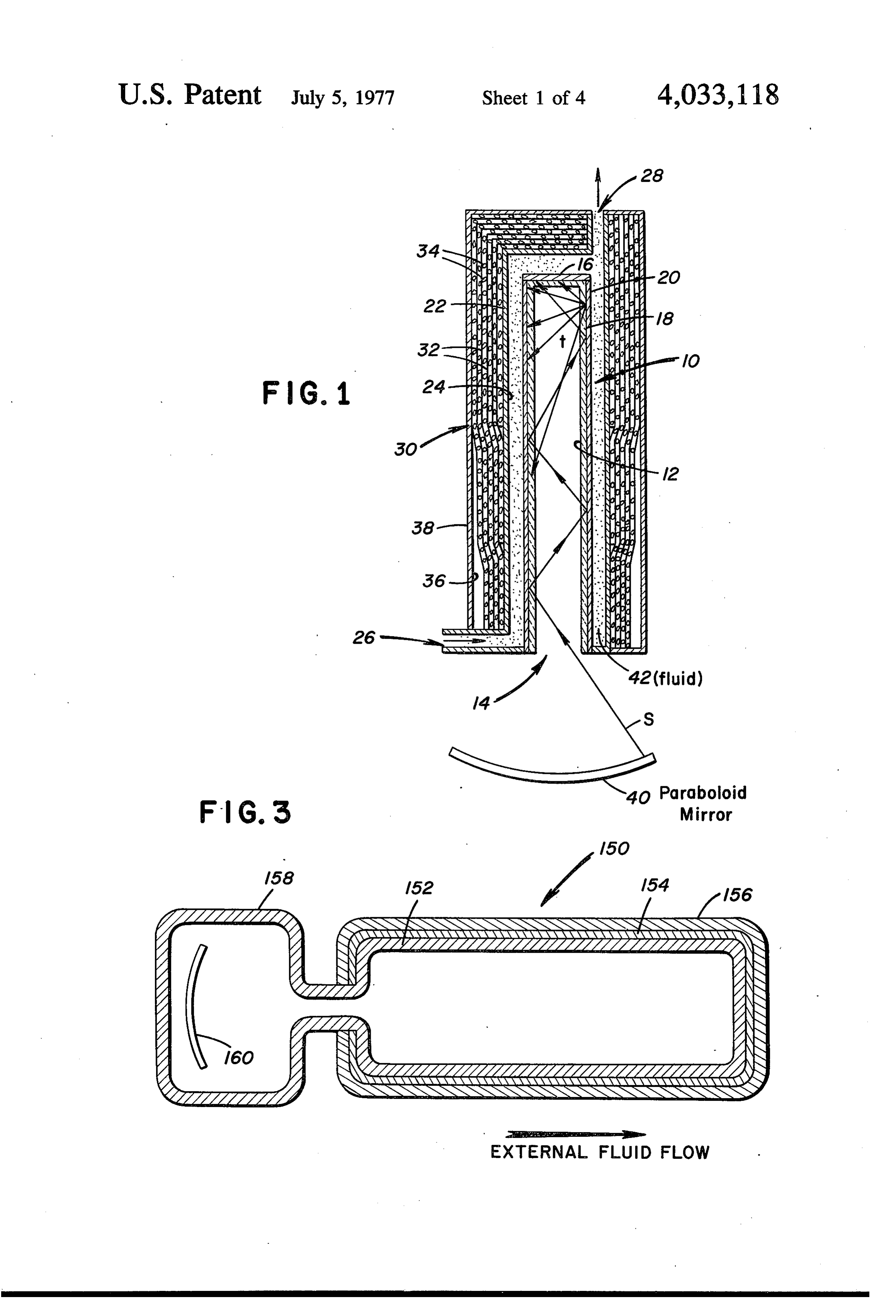
A. Field of the Invention essentially black body end, the entrance end being The invention relates to energy receiving apparatus, located at the focus of any suitable energy concentrat particularly of the collecting type whereby radiation is ing apparatus, such as a paraboloid mirror. The central absorbed by or emitted from the collecting apparatus. longitudinal axis of the member is generally disposed The invention is particularly useful for efficiently col coaxially along the concentrating axis of the mirror or lecting solar energy attemperatures sufficiently high to 10 other concentrating apparatus. Light energy entering permit effective conversion of the collected solar en the absorber, such as from the sun, is absorbed by the ergy to other useful forms of energy. interior walls of the absorber, often after multiple inter B. Description of the Prior Art nal reflections. The interior walls of the absorber being Solar receivers and collectors of the absorbing type comprised of glass, quartz, glass graded into quartz, or are generally limited in their performance at high tem 15 any other absorptive material having the desired ab peratures by reradiation losses which are directly pro sorptive characteristics. The exterior walls of the ab portional to the fourth power of the temperature of the sorber are silvered in a known fashion to promote inter apparatus. Prior art solar energy collecting apparatus nal specular reflections of the non-thermal energy have included "cavity absorbers', such as are disclosed within the cavity of the absorber. The absorber is insu in U.S. Pat. Nos. 3,208,447; 2,793,018; and 2,760,920; 20 lated along its length exteriorly by insulative materials which absorbers are comprised of "silvered' tubular such as metal foils or combinations of metal foils and units having an "entrance' end located at the focus of oxide layers or layers of insulating spheres in a vacuum. an optical system for concentrating the sun's light into A mass flow of a suitably chosen fluid is directed either an absorbing "black body' cavity internal of the tubu externally around the absorbing member or through lar unit. However, reradiation loss from a cavity ab the cavity itself to extract heat from the walls of the sorber of this type at temperatures sufficiently high to member, the flow of fluid acting to induce a thermal be useful in Carnot engines, turbines, or the like is gradient within the member, the entrance end thereof comparable to the energy entering the absorber due to being at a low temperature relative to the closed end of the Teffect mentioned above. Thus, cavity absorbers the member. Thus, the portions of the absorbing mem have proven to be particularly inefficient at the rela ber which are most capable of radiating long tively high temperatures required for efficient Carnot wavelength radiation, i.e., those portions at or near the cycle operation. U.S. Pat. Nos. 3,217,702 and entrance end, are kept relatively "cool' by transfer of 2,872,915 provide means for reducing reradiation loss absorbed heat to the fluid, the fluid being further by reflecting at least a portion of this loss back into the 35 heated during its flow along the member until the fluid cavity. However, the efficiency of cavity absorbers has is removed from contact with the absorbing member at not been appreciably increased until the conception of the closed end thereof.
the present invention wherein reradiation from a cavity Accordingly, it is a primary obect of the invention to absorber is substantially prevented rather than merely cool the entrance end of a high temperature cavity recovered in part. In effect, the present invention pro 40 absorbing apparatus by the flow of fluid along the vides inexpensive apparatus useful with economical length of the cavity to extract absorbed radiation in the solar concentrating apparatus for efficiently converting form of heat from the walls thereof, the fluid flow cre incident solar energy to heat energy at a temperature ating a significant temperature gradient along the ab sufficiently high to perform useful work. sorbing apparatus, the entrance end thereof being cool SUMMARY OF THE INVENTION 45 relative to the opposite, closed end thereof. It is another object of the invention to provide insula
In a simplified form of the invention a cavity absorber tive means for a cavity absorbing apparatus, is cooled at its entrance end by a mass fluid flow It is a further object of the invention to provide a through the entrance end, the fluid extracting heat solar energy utilization system wherein solar energy from the absorbing walls of the cavity absorber during SO collected and concentrated by optical elements is di passing of the fluid through the cavity. The heated fluid rected into a cavity absorbing member for absorption is removed from the absorber at a closed end opposite by the interior walls of the member, the energy thus said entrance end, the energy in the heated fluid then absorbed being extracted as heat by a fluid flow along being either stored or directly utilized for power gener the walls and in thermal contact therewith, the fluid ation or to perform work. The fluid flowing through the 55 flow acting to cool the entrance end of the absorbing absorber is in thermal contact with the interior walls of member to prevent reradiation loss therefrom and to the absorber and creates a temperature gradient in the remove the energy from the member for storage in a cavity thereof, the temperatures being relatively higher thermal or chemical storage unit or for direct use in a at the closed end of the absorber than at the entrance thermal engine or the like. end. Thus, the entrance end of the absorber can be held 60 Further objects and advantages of the invention will at a relatively low temperature which significantly re become more readily apparent in light of the following duces reradiation losses from the absorber. While ten detailed description of the invention. peratures at and near the entrance end of the absorber BRIEF DESCRIPTION OF THE DRAWINGS can be held relatively low, temperatures at the closed end of the absorber can be held relatively high, thereby 65 FIG. 1 is an elevational view in section of a cavity permitting heating of the mass of fluid flowing through absorber according to the invention wherein mass fluid the cavity to a usefully high level while limiting reradia flow is channeled along the exterior walls of the ab tion loss from the cavity. sorber;
Page 7scan →
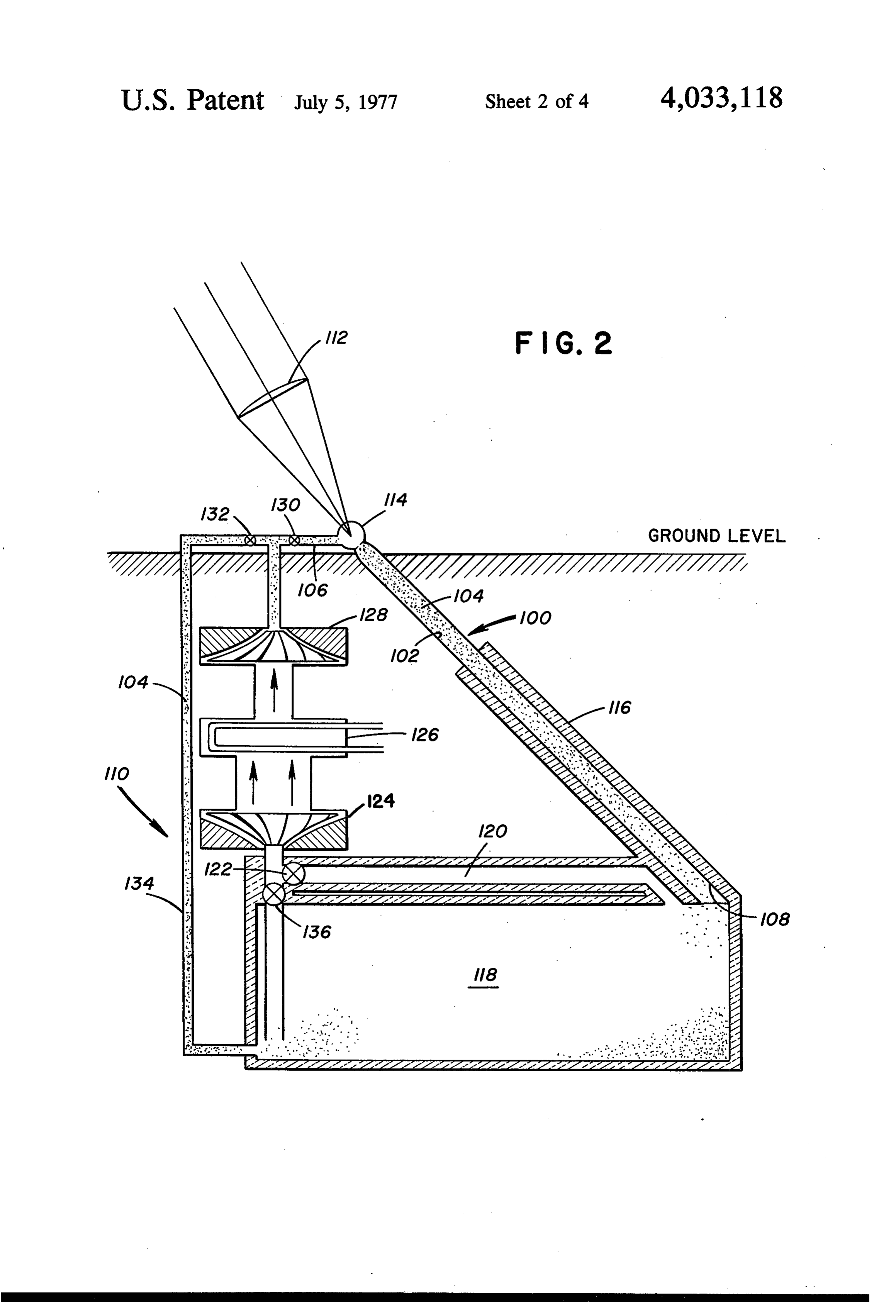
FIG. 2 is an idealized view in partial section of a absorber. A thickness of approximately 1.0 mm in ei thermal energy storage system utilizing a tubular cavity ther case is generally acceptable from an absorptive absorber according to the invention wherein mass fluid standpoint although the wall thickness would normally flow is channeled along the internal walls of the tubular 5 be increased to lend structural integrity. The absorber absorber; 10 is open at its entrance end 14 and sealed with a FIG. 3 is an elevational view in section of an embodi "black' cap 16 at its opposite end. The outer surface ment of the invention illustrating a sealed cavity; 18 of the absorber 10 is coated with a highly reflecting FIG. 4 is a graph illustrating the theoretical model for film 20 such as a silver film or a film of other highly a straight cylindrical tubular absorber with external reflective material such as mercury, nickel, or chro mium. A second member 22 of slightly greater interior fluid flow and a vacuum interior, the overall efficiency 10 dimensions being shown as a function of the absorber efficiency than the external dimensions of the ab which is determined by the ratio of the solar input finite sorber 10 surrounds the absorber 10 and is spaced a energy to the thermal input energy; distance therefrom to define an essentially annu lar circulation chamber 24 between the absorber 10
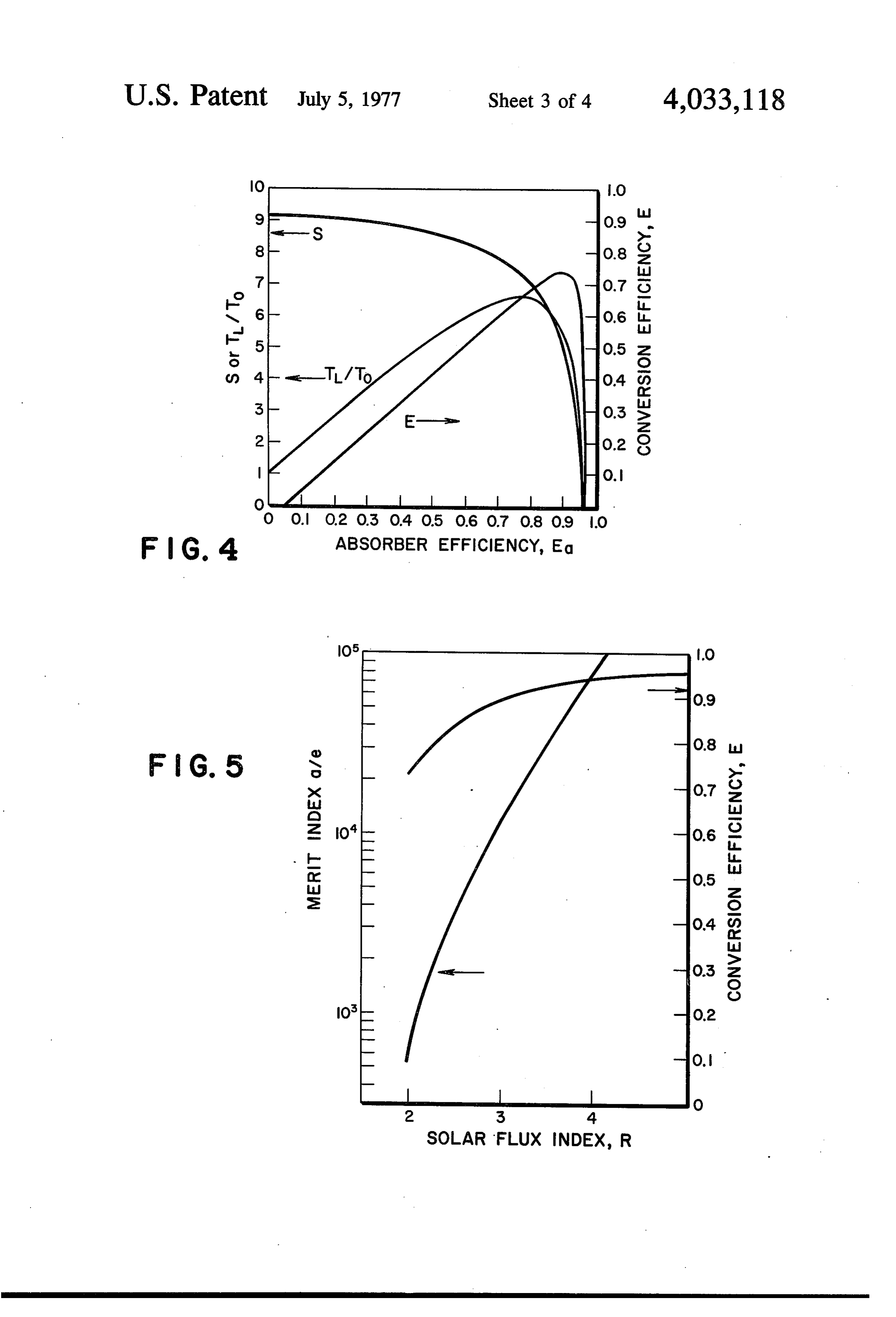
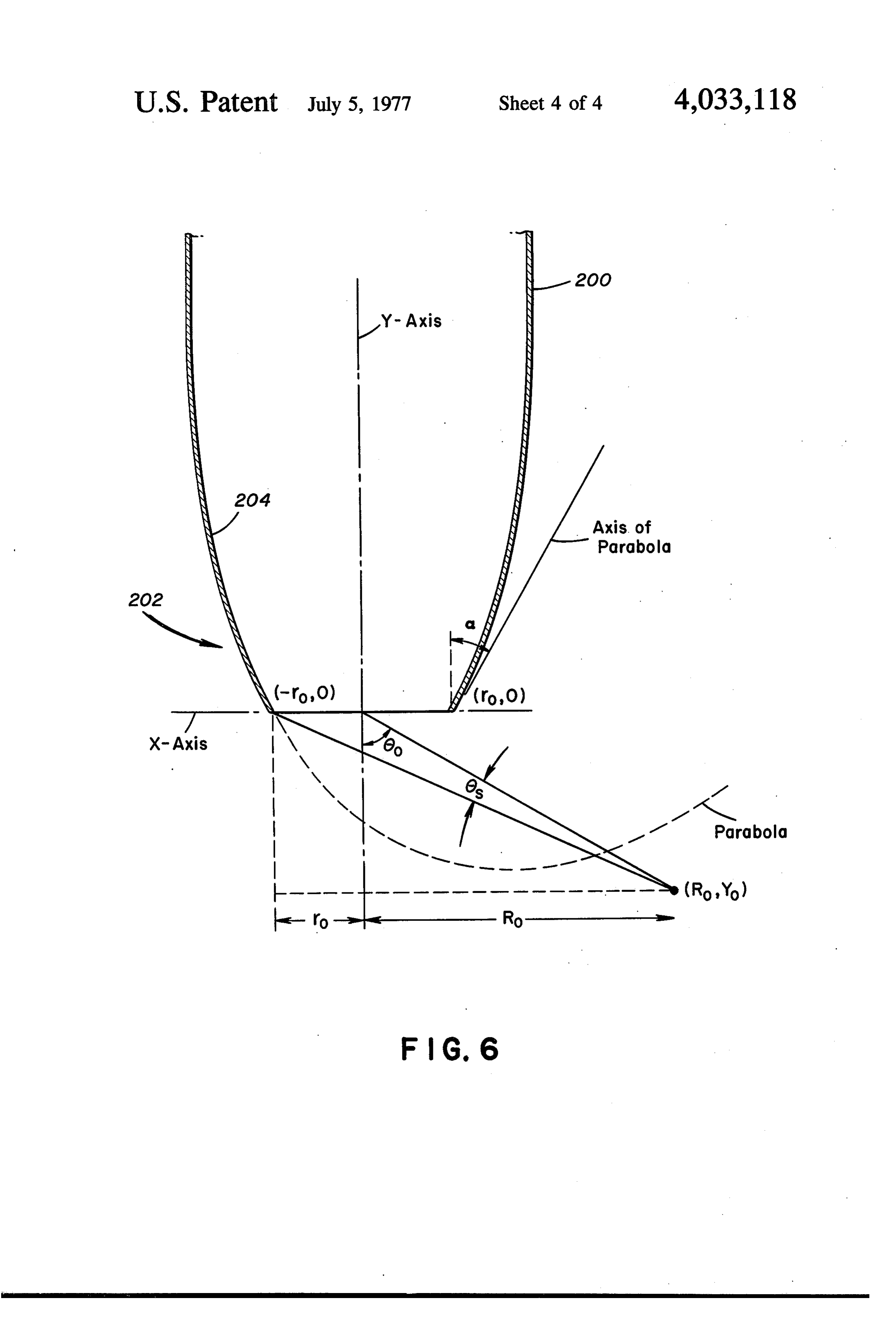
FIG. 5 is a graph illustrating the conversion efficiency and and effective a?e ratio at optimum flow rates for vary 15 may the member 22. The absorber 10 and member 22 each be of a cylindrical, rectangular, or other ing solar fluxes; and, conformation including various cross-sectional geome FIG. 6 is a schematic illustrating the conformation of a particularly efficient absorber entrance end. tries of a tubular conformation as long as the radial dimension is smaller than the longitudinal dimension.
DESCRIPTION OF THE PREFERRED 20 In practice, the longitudinal dimension is at least ten to EMBODIMENTS fifteen times greater than the radial dimension. The The present invention provides in the several em circulation chamber 24 is sealed except for an inlet 26 bodiments thereof apparatus of the energy absorbing near the entrance end 14 of the absorber 10 and an (or emitting) type used as part of an indirect energy outlet 28 near the cap 16 of said absorber. The assem converter, the thermal output of the apparatus being 25 bly thus described is insulated by high temperature converted into power in a thermal engine or the like. In insulation may shown generally at 30, which insulation 30 comprise suitable well-known insulatory materials order for absorbing apparatus to be efficient, black body characteristics have been thought necessary. or which may comprise layers 32 of metal foil sepa However, elevated temperatures necessary for high rated by thin layers 34 of oxide dust, or insulating Carnot efficiency cause loss of absorbed energy by 30 spheres made of hollow glass beads. The layers 32 and reradiation from the absorbing portion of the appara 34 are shown enlarged relative to the remaining struc tus. While selectively absorbing surfaces having high ture for clarification of the structure thereof. The insu absorptivity to emissivity ratios, i.e., a/e, have been lation 30 is held against the exterior walls of the mem fabricated and exhibit values on the order of 10 for ber 22 and within an evacuated chamber 36 defined by temperatures below 500 C, the present apparatus ex 35 vacuum wall 38. The layers 32 of foil may preferably be hibits at its entrance hole (or virtual surface) an effec greater in number at the end of the member 22 oppo tive a?e >500 while producing exhaust temperatures in site the entrance end 14 of the absorber 10, the outer excess of 1000 C. In principle, those portions of the most layer of foil extending the full length of the mem present absorber which would radiate relatively long ber 22 and the innermost layers of foil covering only wavelength radiation are kept cool by transfer of ab 40 reduced portions of the member 22 near the cap 16 of sorbed heat to a mass flow moving through the ab the absorber 10. This insulative design may be utilized sorber from the entrance end thereof toward the oppo to maximize the favorable effect of not only the radial site end of the absorber. The opposite end of the ab temperature gradient which exists inside the absorber sorber is closed and exhibits essentially black body 10, but also of the axial temperature gradient within characteristics, the mass flow reaching its highest tem 45 said absorber. The shorter foil layers at the "hot' end perature at this closed end prior to removal from ther of the member 22 prevent conduction of heat along their lengths back toward the "cold' end of the mem mal contact with the absorber.
A first embodiment of the invention is shown in FIG. ber 22.
1 to comprise a long, thin-walled absorber 10 defining Further discussion of the nature of the member 22 is a central cavity 12, the material comprising the ab 50 believed to be helpful at this point to insure optimum sorber 10 being in the simplest form glass, quartz, or a operation of the absorber 10. The member 22 may be comprised of quartz or fused silica having a continuous combination of the two substances such as will be des, increase scribed in detail hereinafter. The absorber 10 could be of doping-type substances such as NaO (to bored from diamond, sapphire, or quartz as long as about 15%) and CaO (to about 10%) from the closed end thereof toward the entrance end 14, thus forming a transparency is maintained. The absorber 10 could also 55 typical conveniently be formed of a "hollow' rectangular solid soda-lime-silica glass which would absorb infra such as would be formed by two rectangular spaced red radiation particularly well at the entrance end 14, plates enclosed about the perimeters thereof. Practi the member being essentially pure quartz at its hot cally speaking, a glass tube is useful also. Quartz doped portion, i.e., the "closed' end. It is to be understood to yield glass-like properties at the open end portion of 60 that materials other than as specifically described but the absorber and "grading' into a pure quartz at the which exhibit the properties and capabilities described hot portion thereofas will be described is of utility. The herein fall within the scope of the invention due to the teachings herein.
thickness of the walls of the absorber can be as thin as is practically possible as long as infrared radiation can The entrance end 14 of the absorber 10 is disposed at be absorbed thereby. Embodiments of the invention 65 the ing focus of suitable energy collecting and concentrat optics, such as a paraboloid mirror 40. When solar using external flow of a cooling mass are to be made thinner as a practical matter than those embodiments energy is to be collected and utilized with the mirror wherein the cooling mass is flowed internally of the 40, the closed end of the absorber 10, i.e., that end 8 enclosed by the cap 16, is pointed at the sun while the tages brough about by this mass flow in contact with entrance end 14 of the absorber 10 substantially en the walls of the absorber 10, much of the radiation compasses the image of the sun which is formed by the energy entering the absorber 10 will escape as thermal mirror 40. radiation if the wavelength selective properties of the In the embodiment of FIG. 1, the closed end of the walls of the absorber 10 are not properly considered. absorber 10 is pointed at the sun due to the fact that the Only a small fraction of the intense black body radia solar image entering the open end of the absorber is tion filling the closed end of the absorber 10 can escape formed by the single concentrating mirror 40. If a lens directly, i.e., in a direction axially of the absorber. Even is directly used, for example, then the closed end of the so, much of this directly escaping radiation is reflected absorber 10 would be pointed away from the sun as is 10 back into the absorber by the "shadowed' or central shown in FIG. 2. The absorber 10 may be made station section of the mirror 40. It is therefore to be under ary for reasons of economy or may be made to “follow' stood that, for most of the radiation generated by the the sun in a known fashion. In the situation where the walls of the absorber 10 at temperature T or less, the absorber 10 is rectangular in conformation, the en walls are to be opaque. Consequently, the intense wall trance end 4 takes the form of a slit or slot and has 15 radiation at the closed end of the absorber 10 cannot certain inherent "sun-following' characteristics. In “see' the film 20 and “mirror" its way out in a reflect order to maximize overall efficiency, the open end of ing path as did the solar radiation coming into the ab the absorber 10 must encompass most of the sun's sorber. In a known fashion, glass is a convenient mate image. A cooling fluid 42 is directed through the inlet rial for the walls of the absorber 10 due to its opacity to 26, filling the circulation chamber 24, and coming into 20 infrared radiation, this opacity being due to absorption thermal contact with the outer surface 18 of the ab of infrared radiation rather than reflection thereof. In sorber 10. The fluid 42 may be gaseous, such as air, the interest of increased Carnot efficiency, i.e., higher HS, the noble gases, or any heat absorbing gas, or a T, quartz can be used to replace glass at the closed or liquid, such as water, eutectic sodium and potassium, hot end of the absorber 10, the device being more or mercury (in which case the mercury could form the 25 efficient if the glass "grades' into quartz rather than reflecting film 20 as well as the cooling fluid 42. If, as having distinct glass/quartz regions in the absorber 10. in certain embodiments of the invention, the fluid 42 is If quartz is used as the material composing the walls of flowed internally of the absorber 10, the fluid must be the absorber 10, it could be doped with a well-known transparent to light. Otherwise, the fluid 42 may be infrared absorber near the entrance end 14 in order to chosen as desired for properties other than heat ab 30 preserve the selective mirroring action of glass. The sorptive capacity, such as for the ability to chemically walls of the absorber 10 are preferably thin, especially react on exposure to the heat generated at the hot end where heat is to be transferred through the walls, but of the absorber 10 or for heavy atomic mass for driving the walls must be thick enough to be opaque to the wall a turbine, etc. While light flux enters the entrance end radiation. Either quartz or glass is capable of absorbing 14 of the absorber at a multiplicity of incidence angles, 35 most of the heat radiation in the absorber 10, quartz an "average" photon is represented by S in FIG. 1 as being particularly more suitable at higher tempera entering the entrance end 14 and being multiply re tures. However, a grading of these two materials, i.e., flected from the silvered film 20 before being absorbed glass near the entrance end 14 and quartz near the by the walls of the absorber 10 as heat. The thermal closed end of the absorber 10 with a blend or grading of flux incident on the walls of the absorber 10 is much 40 the two materials or with substances approximating the less intense than the flux across the mouth of the en characteristics of the two materials is desirable. For trance end 14. If the absorber 10 be made sufficiently wavelenghts less than approximately 4p, the infrared long such that most of the energy entering the end 14 is transmission "cutoff' for quartz (wavelenghts trans absorbed prior to reaching the end cap 16, then virtu parent to quartz), quartz does not radiate well. Thus, ally all of the energy is absorbed, i.e., a s 1. The fluid 45 even though some black body radiation may be of suffi 42 is contact with the outer surface 18 of the absorber ciently short wavelength to be in the glass transmission 10 absorbs this heat energy from the walls of the ab "window', i.e., s 2p, there is virtually no quartz body sorber 10 and, since the fluid 42 is made to flow from radiation in this region. Thus, the wall material at the the vicinity of the entrance end 14 to the outlet 28 at closed or hot end of the absorber 10 is preferably approximately the same temperature as the closed end 50 formed of a material like quartz having a higher trans of the absorber 10, the closed end of said absorber parent-opaque transition wave length (e.g.,4pithan the being filled with essentially black body radiation char wall material at the entrance end 14, such as glass at acteristic of this temperature which will be referred to 2pu. Further, the two materials can preferably grade hereinafter as T. In practical use, a length to diameter into each other so that for incremental sections of the ratio of approximately 15 is adequate for the absorber 55 absorber 10, a section nearer the entrance end 14, for 10, although it is to be understood that such a ratio is example, will still be a good absorber for the wave not limiting. length that the next section toward the closed end is The flow of the fluid 42 along the walls of the ab "becoming" a “bad” emitter of Stated differently, as sorber 10 removes heat therefrom at a usefully high the transparent-opaque transition wavelength increases temperature, the heat energy in the fluid 42 being 60 with distance from the entrance end 14, any wave thereby utilized in a variety of ways. However, this length radiated well by the relatively hot wall material cooling flow of fluid also serves to prevent reradiation further from the entrance end, and said radiation being loss from the absorber 10 by "cooling' the entrance directed toward the entrance end, will be absorbed well end 14 of the absorber to reduce the reradiation loss by the wall material on which said wavelength is inci which is proportional to the fourth power of the tem 65 dent. Even certain wavelengths not radiated well by the perature. A temperature gradient extending axially more remote hot wall material at the closed hot end of along the absorber 10 thus exists as well as the ex the absorber 10 are still absorbed well by the wall mate pected radial thermal gradient. Even with the advan rial closer to the entrance end 14. Thus, for example, 9 the fact that glass is opaque at 3pu while quartz is trans parent at that wavelength reduces loss of radiation at and, T(x) as T(x) (7) that wavelength when the absorber 10 is structured according to the above description. as the reflected radiation wavelenth distribution is al The following analysis of absorber performance is 5 most identical with the wall radiation and the angular presented to show the improvement over the prior art distribution is nearly blackbody if p - 1. If p - 0, of even the most simple, less efficient embodiment of then the accuracy of Eq. (7) is of little concern. Also the invention. While environmental radiation entering we shall assume that the product of the flow rate of the along with the focused sunlight is neglected in this analysis, such radiation increases the useful output of 10 fluid 42 and the fluid specific heat capacity, Cm, is constant as if the fluid 42 were an ideal gas. If we also the absorber.
The abosrber 10 is assumed to be tubular and to be neglect radial temperature gradients, i.e., assume thin perfectly insulated so that the total energy transport walls, then rate across each cross-section thereof can be taken as C(x) = Cn T(x) (8a) constant. The net power absorber is then seen to be: 15 where:
where S is the ratio of the primary radiation input power to thermal power input, Cn To.
r = distance from the entrance end 14 of the ab 20 Now evaluating Eq. (1) at x = 0 we find, sorber 10;
C(x) = the convective energy rate; -Cn T-F-(1-p)TAT-BT" (0)) (9a) K(x) = the power transported back toward the en = EF (9b) trance end 14 by thermal conduction;
f(x) = the net wall radiation traveling back toward 25 where absorber
EF is the net radiant power captured by the 10 and E is absorber efficiency. Thus at x = the entrance end 14;
F(x) = the short wavelength radiation from the sun 0.
which reaches x without prior adsorption; and, BTT'(0) = F(1 - E)/(1-p) - AT (10a) f(x) = the long wavelength wall radiation escaping from the absorber 10 but reflected back into it and 30 or in general, which reaches x without prior absorption. BTT = Cn(T-T) + F(T, - E) + Gr (10b) Neglecting K(x) due to the low thermal conductivity of the walls of the absorber 10 and, since it increases only linearly with absorber diameter, due also to the 35 where fact that the total cross-sectional area of the absorber G is pF(1 - E)/(1-p) - A T' (Oc) wall and member 22 can be made insignificant com pared to the cross-sectional area of the absorber cavity Thus in dimentionless variables 12, the net wall radiation is:
f(x) = a To" r(x) + BT(x)'T'(x) (2) 40 d(TT) 3.R. -- e.+ where, E.
As (p). (3.a) 45 where and RT is the temperature that a black disk covering
T. E. T(0) (3.c) 50 the entrance end 14 would attain in the cold radiation field of space. Now R, e, p and To are independent and the or is the Stefan-Boltzman constant, D is the parameters but E is dependent on them and S, i.e., Ea, absorber 10 diameter, T(x) is the wall temperature, e isis a monotonically increasing function of Cm. Unfortu the wall emissivity at long wavelengths and t(x) is the nately E(R,ep,ToS) is not known apriori. When Cm is transmission efficiency of the absorber 10 for long 55 large (S small), the temperature achieved deep in the wavelength blackbody radiation. It is also convenient absorber 10, T., (L-D) is low. Hence, even though E. to describe the other radient fluxes in terms of trans is large when Cm is large, the overall efficiency mission factors, (x) and Tr(x).
Thus, E is E.E. (12)
F(x) = F(x) (4) 60 is low because the thermal-to-mechanical power con version is limited by the Carnot efficiency (13) f(x) = pf(0), (x) (5a) E = 1 - TVT where:
(5b) where we have assumed T is also the Carnot exhaust 65 temperature as if the fluid 42 were also circulated through the Carnot engine as the working fluid. Since in Eq. (10b), T, T and T'all approach zero as x - co,
Page 10scan →
E = Cn (T-T) Fo (14a) Eqs. (18), including E, is a few percent too low. Thus, or in terms of S the Carnot efficiency and consequently the overall
(TIT) = 1 - SE (4b) efficiency. E calculated with Eqs. (15) is underesti mated by a few percent if the Cm is taken at the largest and consequently, value permitted by Eq. (18). E = Cn (T-T) (TF) (15a) It iss =possible or in terms of S
E = SE (TFT) (15b) and however, T, and consequently E are also unknown = 0.5 (19b) functions of Cm (or S) assuming the parameters Rep and T are fixed. as plausible values for attenuation coefficients of short In order to find the monotonic function, E. (Cm), and long wavelength radiations propagating in the ab and consequently T(Cm) or Ti(S) via Eqs. (14) and 15 sorber 10. It is also possible to take then E(Cm) or E(S) via Eqs. (15) we first characterize e is 0.9 (9c) the system under study by a set of values for the param eters of Eq. (11), and also for both p, the wall reflectiv ity for the incident short wavelength flux, and f(0), its p = 0.5 (19d) angular distribution, so that r(x) can be calculated. 20
Then we select a particular E of interest, calculate G as a conservative estimate of the fraction of wall radia and guess a test value of Cm wich we shall designate tion which can be reflected back into the absorber 10 C . If C > Cm, then as Eq. (11) is solved for T(x) with a good optical design, e.g., a phocon entrance at increasing x, using the initial conditions, the deriva such as will be described hereinafter or external mir tive T'(x) will remain too large for x 2 0 and in fact T. 25 rors. Next for a particular R, i.e. R-2, we assume vari - Oo. Likewise, if C, < Cm, then T -> -oo as x - o. Consequently, for each physically realistic E there ous values for E and with Eq. (18) calculate the corre is a unique value of C for which T remains finite as spondingE from value of S and then for this S and E calculate
Eq. (15b). The results of this R-2 case are x - oo and the relationship between E. and Cm or S is shown in FIG. 4 and we see that a maximum overall found from this condition. 30 efficiency of 73% results when E = 90%. More rapid But, for a simplified but practical example of this fluid flow produces higher absorber efficiency but low procedure, we assume ers the exit temperature excessively. Likewise less T(x) = et (16a) rapid coolant flow can result in better Carnot effi ciency, but reradiation losses reduce R excessively.
rather than calculate T(x) for some particular but 35 The efficiency at optimum coolant fluid flow rate for equally arbitrarily chosen f(6). Likewise for simplicity other values of R is shown in FIG. 5. in the illustration of this method we take A conventional black absorber-radiator in the same solar flux would have much greater reradiation losses,
T(r) e e-brid (16b) lower E and reach temperatures far less than T. For 40 example, a conventional black absorber in an R=2 flux as a reasonable facsimile of a very complex function. has a peak temperature even with no useful power . Then differentiating Eq. (10b), output of only 2T, thus it's Carnot efficiency would not exceed 50% even if the over all efficiency fell to zero. Thus, the present absorber 10 is three four times
Cr' - (f)F. T - (i)a. (17) more efficient and functions well in poorly concen
We can define an effective emissivity, e, for the sur
If T'(0) 2, 0, then Cm is too large as with uniform face of the entrance end 14 in terms of the exhaust solar reflectivity, the rate of temperature increase must temperature achieved and the reradiation losses, i.e. decrease with length. 50 F (1-E) as e A T. (20) Thus evaluating Eq. (17) at x = 0.
and a = 1 as we have already noted
Thus l (sE - bo) D. (18a) 55 or in terms of the dimentionless variables of our model, s + bp (1 - E)/(1-p) - bR. an 60 1 - SE;
Often the true value of Cm (or S) differs from the equality value given by Eqs. (18) by only a few percent. This effective ale at optimum coolant flow rate is also We will avoid numerical analysis here and continue by shown in FIG. 5. In general, this merit index shows that using the largest value of Cm permitted by Eqs. (18), 65 the present invention is much superior to the prior art. i.e., the equality value. This approximation is conserva This analysis has assume that the absorber 10 was tive as the value of T calculated from Eqs. (14) for deployed in the cold radiation field of space. Because fixed values of all the parameters on the right side of of its high efficiency, relatively little waste heat must be 11 rejected. Thus, in space, with a relatively small waste infrared radiation from the walls of the absorber by the heat radiator located in the shadow of the concentrat water molecules in the air decreases the wall radiation ing mirror 40, To << 300 K would be possible. Then escape probability and further improves thermal effi rather large values of T/To could be tolerated without ciency. Thus, any fluid 104 so used an be chosen for its damage to a quartz absorber. In addition to higher 5 infrared radiation absorptive ability as well as for its predicted efficiency, for units producing several KW or heat transfer capability. Alternately, desireable fluid more, this absorber and advanced turbine generators 104 may be a mixture having one or more components developed for sapce applications offer significantly with infrared absorption ability. The use of water va lower cost and lift off weights compared to either solar por-laden air as the fluid 104 is simply an example of an cells or isotopic power supplies. O inexpensive, non-polluting, non-toxic, readily available On earth To 2 300 K and material problems limit fluid having adequate heat transfer capability and infra the T/To ratio to about 5. Thus for most of the day, red absorbing ability. While not shown in detail, a com even in northern lattitudes, the fluid flow rate would be bination of fluid flow against the external walls of an automatically controlled to maintain the highers possi absorber, such as the absorber 10 of FIG. 1, and ble Carnot efficiency permitted by the construction 15 through the central cavity of a absorber, such as the materials and the absorber 10 would operate at greater absorber 100, is useful, heat being thereby transferred than optimum efficiency. A linear slot absorber (not from such an absorber both internally and externally shown) over a parabolic mirror such as 40 is also at thereof while infrared absorption by the interior fluid tractive and may also be able to produce a materials adds its benefit to the structure. The only significant limited exhaust temperature. 20 requirement of the fluid 104 is that it be transparent to In spite of the fact that E is nearly unity, economic the desired electromagnetic wavelengths of sunlight. considerations would result in a significant part of the Further referring to FIG. 2, a solar power plant is sunlight collected by the concentrating mirror 40 being generally shown at 110 to utilize the energy obtained poorly focused and wasted. However, unlike the uncol from the absorber 100 through thermal storage of said lected waste heat that goes up the chimney of a conven 25 energy. Referring back to the absorber 100, it is seen tional power plant and adds to the local environmental that an optical focusing device, such as a lens 112, heat load, this concentrated sunlight can be reflected focuses solar energy through a transparent dome win so as to escape from the earth at negligible incremental dow 114 into the entrance end or mouth of the ab cost. Thus there need be no change in the local albedo. sorber 100. The lens 112 may be operated by suitable Since this simple, economic, absorber 10 is not danger 30 mechanical apparatus to image the sun into the en ous, does not require intense sunlight, and need not trance end of the absorber 100. The interior of the have any net local ecological impact, it could be lo absorber 100 forms a part of a pressurized flow path for cated in urban power demand areas to avoid transmis the fluid 104 through the plant 110, the walls of the sion losses. It could also be used to make fuel by pro absorber 100 extending to the dome window 114 at the ducing hot steam for known chemical cracking pro 35 entrance end thereof and being insulated by insulation 116 at and near the outlet end thereof.
Ccsscs
The fluid used to extract heat from the absorber 10 A solar energy entering the absorber 100 reflects through the walls thereof may be in the gaseous or deeper thereinto, the temperature of the walls in liquid state. A mixture of gases, such as air, is perfectly creases. The fluid 104 passing through the central cav suitable as well as would a mixture of liquids, such as 40 ity 102 extracts heat from the walls and emerges as a sodium and potassium. While a sodium-potassium mix relatively hot fluid at the outlet 108. The hot fluid then ture would be particularly suited to use for direct drive enters a subterranean thermal energy storage tank 118 of a turbine or the like, any substance in a fluid state is which is suitably insulated. The storage tank 118 can be useful in the practice of the invention since any fluid made of iron and filled with a brick lattice work which substance would have heat transfer capability. 45 permits the fluid 104 to circulate through it with effi As can be seen in FIG. 2, an absorber 100 has a cient energy transfer between the fluid and the con longitudinal cross-section at its inner end, or cold end tents of the tank. The insulation for the tank 118 might which is generated by revolution of a paraboloidal simply be dry and 10 to 20 feet thick surrounding the segment as will be described hereinafter. The absorber iron tank on all sides, the dry sand being contained in a 100 further has a central cavity 102 defined by the 50 vented masonry chamber (not shown) to prevent ex walls thereof. A heat transfer fluid 104 is drawn . cessive intrusion of ground water. The heat and the through the central cavity 102 itself to absorb heat vent assure that the sand remains dry. The inner most from the interior walls of the absorber 100. The heated layers of and adjacent to the tank can provide addi fluid 104 is ducted through the absorber 100 from an tional energy storage. Radial fins can be attached to the inlet 106, substantially through the length of the central 55 iron tank, to facilitate radial heat flow. Longitudinal cavity 102, and through an outlet 108, the fluid 104 fins should not be used as axial heat coduction through absorbing heat from the walls of the absorber 100 on the tank 118 is undesirable as will be explained herein movement therethrough. Thus, transfer of energy after.
through the walls of the absorber 100 is avoided in this Some or all of the hot fluid 104 passes through a tank embodiment. The heated fluid 104 withdrawn from the 60 bypass tube 120 and a tank bypass alve 122 to enter a outlet 108 may be used as desired, one potential man motor (expansion) unit 124 and produce useful work. ner of its use being described hereinafter. The flow of The fluid 104 is still warm when it enters a counterflow the fluid 104 through the absorber 100 acts to over heat exchanger 126 which extracts heat from the fluid come heat loss by conduction within said absorber and so that a relatively cold, low pressure flow of fluid also acts to extend the high temperature region further 65 enters a compressor 128 located in the system. The into the absorber, thereby improving the thermal effi output flow from the compressor 128 is a cool high ciency thereof. If the fluid 104 be taken to be air having pressure fluid which is directed through a day valve 130 water vapor as a component part thereof, absorption of back into the tubular absorber 100 if sunshine is avail 12 able or through a night valve 132 if inadequate sun storage mass within the tank 118, there is less danger shine is available. than in a conventional steam boiler. At night time or during periods of low light levels, Enclosure of the absorber 100 as shown in FIG. 2 to when the night valve 132 is open, the relatively cool protect the device from the elements is desirable. The high pressure fluid from the compressor 128 passes 5 concentrating optics may also be economically and through a night line 134, into the left end of the thermal advantageously enclosed for protection. Use of a fluid energy storage tank 118 remote from the absorber 100 104 having strong absorption capability in the infrared and a "store energy' valve 136 is closed. Thus, the prevents escape of wall radiation as described previ night time flow of fluid 104 through the storage tank 10 ously by internally reabsorbing the energy. This absorp 118 cools an increasing volume of the left end of the tion effectively prevents wall radiation from escaping storage tank but is heated to almost the temperature of and at high temperatures significantly aids in the radial the right end in a relatively short section of the storage transport of energy in the cooling fluid 104 and reduces tank and does not appreciably reduce the temperature radial temperature radients. Unfortunately, the radia of the right end. Thus, the storage tank 118 has a cool 15 tion from the hot fluid 104 partially replaces the wall left region, a relatively short temperature transition radiation it prevents. However, at no wavelength can Zone, and a high temperature right region. During the this hot fluid radiation exceed the essentially blackbody night or other times when energy is extracted from the radiation it replaces. Thus, the net effect is beneficial. storage tank, the transition zone moves into the high With uniform solar reflectivity the thermal flux on temperature region which decreases in volume, and the 20 the walls of the absorber decreases with distance from cool, left region grows in volume. Axial conduction in the entrance end. Because of this fact and the fact that the brick lattice work is undesirable as it tends to make the fluid temperature is steadily increasing, the heat the temperature of the storage tank more uniform and flux into the fluid decreases with distance more rapidly thus lower the temperature of the gasses entering the than the thermal flux ol, the walls. Economic consider expansion motor unit 124. ations related to the insulation cost can make an inten During those daylight hours when more energy is 25 tional reduction in the solar reflectivity with distance available than required, the store energy valve 136 is from the entrance end desirable even though the rera partially open and tank bypass valve 122 is partially diation losses would increase. Thus, shorter absorber closed. Then part of the hot flow of fluid 104 from the tube lengths with the same net solar absorption are tubular absorber 100 is drawn through the energy stor 30 possible.
The conformation shown in FIG. 2 for the absorber age tank 118 and the temperature transition zone is moved into the cool left region which decreases in 100 at its entrance end, or cold end, should now be volume as energy is added to the energy storage tank, described in greater detail due to the great increase in This part of the flow passing through the store energy absorber efficiency which can be attained with the use valve 136 is cool and mixes with the hot flow from the 35 thereof. This particular conformation can be employed tank bypass valve 122 as shown. Under certain circum to advantage with any of the embodiments described stances, it is desirable to avoid excessive reduction in herein, even though paraboloidal sections or any virtu the inlet temperature of the expansion motor unit 124 ally any shape having a longitudinal cross-section and yet also desirable to make the flow through the whereby the absorber increases in section with distance energy storage tank 118 relatively large. This is possi 40 from the inner (or entrance) end thereof. As seen in ble if part or all of the flow through the energy storage FIG. 6, an absorber tube 200, is shown to be formed as tank 118 is forced by a pump (not shown in FIG. 2) a right circular cylinder except at its entrance end 202, backwards through the night line 134 and the night the entrance end 202 having a cross-section which valve 132. If no output power from the motor unit 124 increases with distance from the entrance end 202 is desired, then all of the flow through the absorber 100 45 toward the cylindrical body of the absorber tube 200 so can be pumped backwards through the night line 134 that solar radiation collected by the surface of the con and night valve 132 to achieve maximum storage of centrating optics of radius R associated therewith near energy. the rim of said optics is converted into more nearly During hours of intense sunlight, the flow through the paraxial rays after the first reflection inside the ab absorber 100 is relatively large and maintained to avoid 50 sorber and thus travels much further thereinto before damage to the absorber. At night and at other times being absorbed. The entrance end 202 is formed of a when the flow downward through the absorber 100 is paraboloidal having one segment 204 of rotation, the segment 204 end fixed at the point (-ro) on the Carte inadequate to prevent natural convective heat transfer upwards through the absorber, it is closed off by an sian axis, the parabola of which the segment 204 is internal insulating plug (not shown in FIG. 2). The 55 taken having its focus at the point (r, o) and having its thermodynamic cycle for the plant 110 is closed and axis inclined to the y-axis by the angle o. Thus, the the working gas of the expansion motor unit 124 is the equation for the segment 204 is given by: same as employed in the absorber 100 in the system (x-r) cos a -y sin a) = 4r,(1+sin a) (x sin a +y shown in FIG. 2. Carbon dioxide and/or steam are cos or -- r) attractive for use as the fluid 104 as they are chemically 60 stable at high temperatures, have strong infrared ab Rotation of this curved segment 204 about the y-axis sorption bands, are relatively noncorrosive and have generates the "paraboloidotoridal phocon' which is adequate molecular weight to permit economical tur the shape taken by the entrance end 202. In the pre bo-compressor designs. Further, the energy storage ferred embodiment, the choice of the angle a is usually tank 118 is far below ground level; thus, even a rapid 65 related to the rim angle of the concentrator optics 0, by pressure failure in the high temperature storage tank 118 is unlikely to cause damage at ground level. Since or = t2 - 6 most of energy in the system is stored in the thermal 13 but other relationships between 0 and a are practical. given, it should be recognized that chemical, electrical, The length of this entrance end 202 is arbitrary but may and other mechanical apparatus may be so employed. be usefully limited by its intersection with the line given For example, the hot fluid absorber according to the by: invention could be used for smelting a metal ore by y t an a = - x. direct contact with the hot fluid. Further, the fluid in an This shape acts to decrease the angle by which rays are absorber according to the invention can be chosen so inclined to the axis of the tube 200. It is to be pointed as to be capable of maintaining a net electric charge, out that r is taken to be the radius of a circle contain the absorber being arranged as a thermoelectric gener ing all rays in the focal plane of the concentrating op 10 ator to produce a useful effect either inside or outside (or both) of the absorber. The invention, as described tics and subtends a half angle 6, equal to the source. hereinabove
The relationships described can be used to generate and defined by the following claims, is entrance end conformations suitable to varying uses therefore seen to be useful in a variety of applications depending on the maximum angle of inclination of where radiant energy is to be collected and utilized. those rays which are desired to be focused into the 15 claim:
absorber tube 200. As an example, if the rim angle of a 1. Apparatus for facilitating energy flow, comprising: concentrating mirror is 60 the length of this initial body means having walls which define a cavity and an phocon entrance end 202 required to convert all rays entrance opening to the cavity; to 30' or less inclination to the absorber axis is only a flowable mass of material; at least a portion of 1.15 maintube (tube 200) diameters. The entrance which material is disposed within the cavity and area for this example would be only 28% of the ab 20 comprises a fluid composition capable of undergo sorber cross section and consequently much of the ing a chemical change on exposure to energy; shortest wavelength wall radiation or hot gas radiation means for directing energy into the entrance opening not blocked by the selective mirror action of the walls of the body means;
would fail to escape from this convergent phocon exit. 25 means surmounting the entrance opening of the body Both the increased distance between reflections for the means and sealing said cavity from ambient, said solar radiation propagating into the absorber tube 200 means being transparent to the energy being di and the relatively larger main tube diameter also act to rected into said entrance opening; and, make the thermal wall flux load very much smaller than means for directing a flow of said mass along the the entrance flux. It is to be understood that any in 30 walls of the body means away from the entrance creasing cross-sectional portion at the entrance end of opening thereof to cool certain portions of said an absorber improves performance. The cross-sec body means which are near the entrance opening tional shape may be conical or otherwise than is shown relative to other portions of said body means rela particularly in FIGS. 2 or 6. tively further away from said entrance opening. Referring to FIG. 3, a sealed absorber 150 is shown to comprise an absorber body 152 silvered for reflec 35 2. The apparatus of claim 1 wherein the energy di tive purposes by a silver layer 154 and insulated by an rected into the entrance opening of the body means is insulative layer 156. The body 152 has an integral win non-thermal energy.
dow portion 158 which encloses an optical focusing 3. The apparatus of claim 1 wherein the walls of the mirror 160. In this embodiment of the invention, the 40 body means are at least partially transparent and absor interior of the cavity defined by the body 152 is sealed bent to the energy directed into the entrance opening from ambient and has an internal atmosphere of a de of the body means, the walls being covered over at least sired nature, such as gases which are capable of under a portion of their surfaces opposite those surfaces de going a chemical change on heating thereof by the fining the cavity with a reflective layer, the energy absorbed solar energy. The flow of fluid for cooling the 45 entering the cavity of the body means through the en absorber 150 (not shown) could also be external of the trance opening being reflected by said layer into the absorber body 152 in this embodiment. The window cavity in a direction away from the entrance opening portion 158 may be a focusing optical element itself or for absorption of said energy by said walls, the flow of may be a bundle of optical fibers for concentrating mass along the walls cooling those portions of the body energy into the entrance end of the body 152 by inter 50 means nearest the entrance opening relative to those nal reflection. portions of the body means located relatively more Energy developed in the present absorber structures distant from the entrance opening, thereby to prevent may also be stored chemically such as heating water (or other suitable fluid) either internally or externally (or thermal trance reradiation from the cavity through the en opening.
both) of the absorber structure to produce steam at a 4. The apparatus of claim.1 and further comprising desired temperature, such as 1300 to 1400 K, and 55 insulation disposed about the body means, the insula then directing the heated steam against a substance or tion comprising alternate layers of thin metal and dust mixture of substances to cause a reaction which effec tively stores energy. As an example, an alkali oxide may like particles separating the layers of thin metal. be decomposed in this fashion. On cooling of the steam 5. The apparatus of claim 1 wherein the walls are (to 600 to 700 K) some of the steam could be used to 60 formed of a material more transparent to the energy react with the alkali metal previously produced to pro entering the cavity than to the radiation from the walls duce hydrogen, this substance essentially storing the resulting from energy absorbed by said walls. energy developed in the absorber for later use, such as 6. The apparatus of claim 1 wherein the walls are by burning. The chemistry of such an operation is simi formed of material relatively near the entrance opening lar to that described in U.S. Pat. No. 3,490,871. 65 which is a good absorber of infrared radiation relative As is obvious, many techniques may be employed to to the material of which the walls are formed at por utilize the energy-laden fluid as it exists either one of tions of the body means relatively further away from the absorbers 10 or 100. While one example has been the entrance opening. -
Page 14scan →
7. The apparatus of claim 1 wherein that portion of 12. The apparatus of claim 1 wherein the mass of material is comprised of a substance absorptive of in the walls of the body means relatively near to and de frared radiation.
fining the entrance opening is formed cross-sectionally 13. Apparatus for facilitating energy flow, compris as a paraboloidal segment, the segment being mirror 5 Ing:
imaged across the longitudinal axis of the body means. body means having walls which define a cavity and an 8. The apparatus of claim 7 wherein the paraboloidal entrance opening to the cavity, the walls being segment is defined by the relation: formed of material relatively near the entrance opening which is a good absorber of infrared radia (x-r) cos or -y sin a' = 4r(1 - sin or) sin a -- O tion relative to the material of which the walls are y cos or r) formed at portions of the body means relatively further away from the entrance opening;
wherein: a flowable mass of material; and, r= the distance of a point on the entrance opening 15 means for directing a flow of said mass along the from the longitudinal axis of the body means; and, walls of the body means to cool certan portions of or = inclination of the axis of the paraboloidal seg said body means relative to other portions thereof. 14. The apparatus of claim 13 wherein the mass of ment from the longitudinal axis of the body means. material is comprised of a substance absorptive of in 9. The apparatus of claim 1 wherein the entrance end frared radiation.
is formed into a slot, the slot being aligned with a line 20 15. The apparatus of claim 13 and further comprising focus energy directing means. means for directing energy into the entrance opening of 10. The apparatus of claim 1 and further comprising: the body means, the flow of mass being directed by said mass thermal storage means for receiving the mass of ma opening flow directing means away from the entrance terial after contact of said mass with the walls of 25 16. Theofapparatus said body means.
of claim 13 and further comprising the body means; window means surmounting the entrance opening of means receiving said mass from said thermal storage the body means and sealing said cavity from ambient. means for producing work; and, 17. The apparatus of claim 16 wherein the energy means for returning said mass to the body means directing means are disposed within the sealed confines after work has been produced in the work produc 30 of the window means.
ing means. 18. The apparatus of claim 13 and further comprising 11. The apparatus of claim 10 and further comprising the bodymeans window surmounting the entrance opening of means and sealing said cavity from ambient, means for selectively returning said mass either to the the means for directing a flow of said mass being dis body means or to the thermal storage means after work 35 posed within the sealed confines of the window means. has been produced in the work producing means. sk
Provenance
- Collection
- Patents citing this work
- Pages
- 14
- Method
- pdftotext (the PDF's own text layer) + pdftoppm 300dpi page scans
- Patent office record
- patents.google.com →
- Source
- Google Patents citing-documents table
- Assignee
- Powell William R
- Published
- 1977-07-05
- Transcribed from
- patentimages.storage.googleapis.com →