

patent · US4036012A
Laser powered rocket engine using a gasdynamic window
19 July 1977
Text
Page 1scan →
Monsler
(54) usingagasdynamic
Laser powered rocket engine
Window
75 Inventor: Michael J. Monsler, Reading, Mass. 73) Assignee: The United States of America as represented by the Secretary of the
Army, Washington, D.C.
51 Int. C.’............................................... H05H 1/24 52 U.S.C. ................................... 60/203; 219/121 L
3,083,528 4/1963 Brown .................................... 60/2O3 3,392,527 7/1968 Gilmour et al. ...................... 60/202 3,825,211 7/1974 Minovitch ............................. 60/203 3,885,884 5/1975 Wilkinson .................... a sa saw a 417/65
Propellant
Other publications
Parmentier et al., "Supersonic Flow Aerodynamic Win dow for High-Power Lasers', AIAA Journal, July,
Primary Examiner-Carlton R. Croyle
Assistant Examiner-Robert E. Garrett
Attorney, Agent, or Firm-William G. Gapcynski; Lawrence A. Neureither; Freddie M. Bush
Optics capture and concentrate laser radiation and send it through a gasdynamic window which is formed by supersonic expansion of unseeded hydrogen gas exiting a passageway directly under the opening. Seeded fuel is inserted into the chamber where it is heated by the laser radiation and the energy of the heated gas is converted into kinetic energy of a high velocity by means of a rocket nozzle.
3 Claims, 5 Drawing Figures
Incoming radation
Transparent
Exhaust gas
Drawings
Page 2drawing sheetscan →
Page 3drawing sheetscan →
Page 4drawing sheetscan →
Page 5scan →
LASER POWERED ROCKET ENGINE USINGA DESCRIPTION OF THE PREFERRED GASDYNAMICWNDOW EMBODIMENT
DEDICATORY CLAUSE This disclosure describes a new type of laser powered 5 rocket engine. A laser powered rocket engine is a de
The invention described herein was made under a vice which produces useful thrust for propulsion of a contract with the Government and may be manufac rocket, using the energy provided by laser radiation tured, used, and licensed by or for the Government for which is beamed up to the rocket from a laser located governmental purposes without the payment to me of on the ground. The Laser Powered Rocket Engine any royalties thereon. 10 (LPRE) is the device which converts power carried by BACKGROUND OF THE INVENTION laser radiation (electromagnetic waves or photons) into power in an exhaust jet of high velocity gas. The jet of
Many systems have been tried in the past to use laser gas provides the thrust similar to the operation of an energy to create propulsion for a rocket system. See the ordinary chemical rocket engine. patents to William C. Brown, U.S. Pat. No. 3,083,528; 15 The laser powered rocket engine must have three key William C. Brown, U.S. Pat. No. 3,114,517; and Mi components. These are:
chael Minovitch, U.S. Pat. No. 3,825,211; and the arti a. Some form of optics to capture and/or concentrate cle entitled "Laser propulsion' by Frank E. Rom et al, the laser radiation.
published April 1972 by NASATM X. All of these 20 b. Some way to absorb the laser radiation in the pro prior publications suffer from impracticality of the ar pellant to provide a hot gas or ionized plasma at very rangements of the collection of the laser radiation and high temperature.
the transmission of it to the propulsion medium. c. Some type of rocket nozzle to expand the hot gas to SUMMARY OF THE INVENTION form a supersonic jet useful for producing thrust by the principle of action and reaction.
The invention concerns a new type of laser powered 25 These same processes may be stated in different words rocket engine. The laser powered rocket uses a system in the following three corresponding steps. of optics (mirrors) to concentrate an earth-bound laser a. Energy in the form of a flux of radiation which is at beam in the critical zone of the rocket where the beam a low flux density so that it can be transmitted through energy is absorbed by the propellant. A rocket nozzle is the atmosphere without being absorbed, and is concen provided to expand the hot gas to form a supersonic jet 30 trated by the use of mirrors so that it can be better exhaust. Supersonic expansion of gas is used to create absorbed in the propellant.
sufficiently large pressure differences to form a window b. Energy in the radiation field is converted into heat in the rocket stagnation chamber. The "seed' which is or thermal energy of the propellant gas by absorption. added to the propellant to absorb the laser radiation is 35 c. Thermal energy of a slow moving gas is converted added after the window. The unseeded propellant, hy into kinetic energy of a high velocity jet by means of a drogen or helium, is transparent to CO2 laser radiation rocket nozzle.
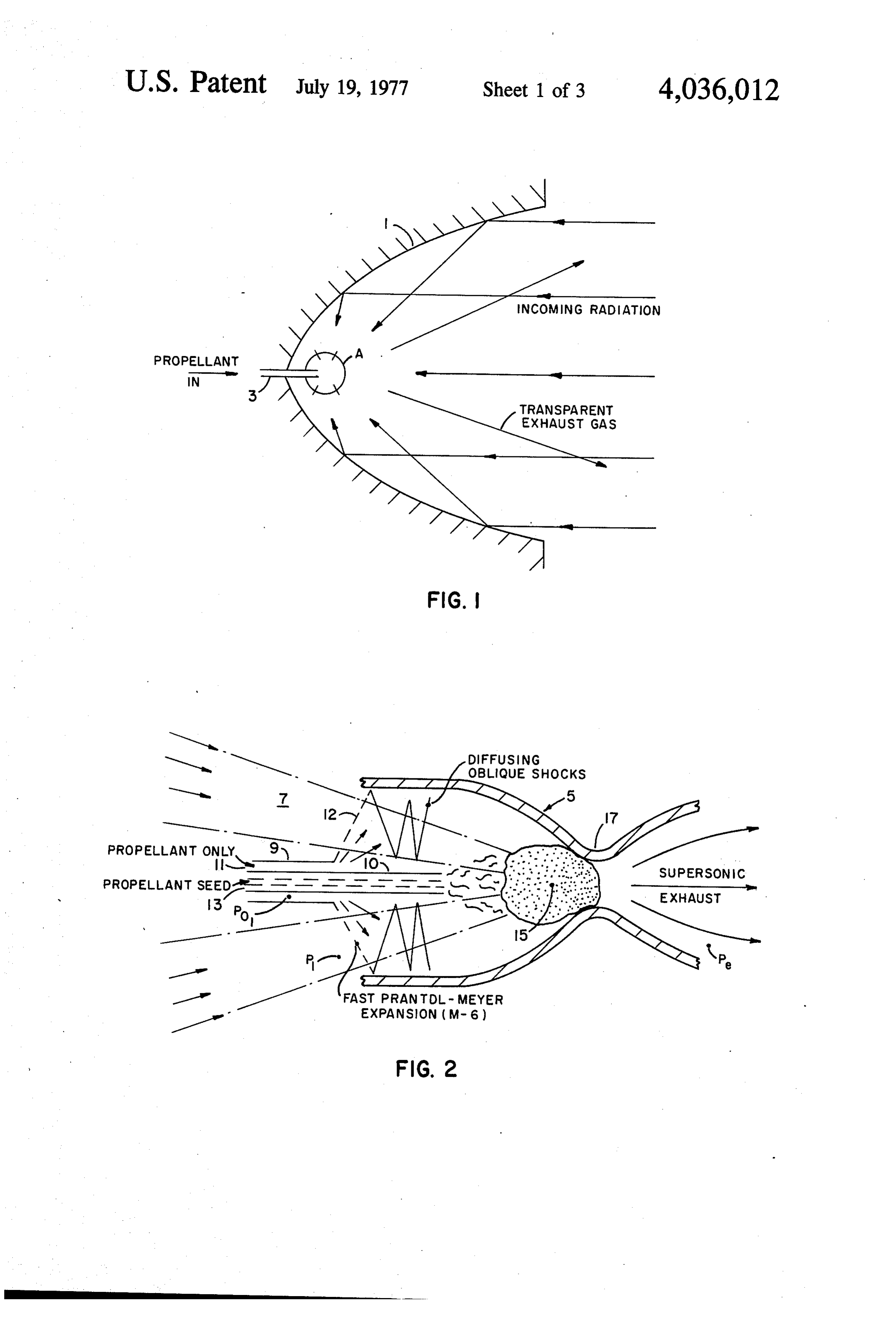
at 10.6 L when the gas is not ionized. An annular ring One way of making a LPRE is illustrated in FIG.1. A mirror or rotatable collecting mirror is arranged exter combination parabolic mirror and rocket nozzle 1 is nal to the rocket for collecting the earth-bound laser used; combining the functions of (a) and (b). The incom radiation and directing it through apertures in the stag ing radiation is reflected off the parabolic mirror to the nation chamber of the rocket engine. An apparent 'win sonic surface A. Propellant is fed in through a nozzle 3 dow” across the apertures is formed by the supersonic to the sonic surface A where it is heated by the incom expansion of unseeded hydrogen gas exiting a passage ing radiation which is focused on the sonic surface A. way directly under the opening. Unseeded liquid hy 45 The propellant expands out and provides propulsion for drogen is forced through oppositely disposed tube-like the rocket and produces transparent exhaust gas to the passages on the outer framework of the engine, begin incoming radiation.
ning at the nozzle. As the unseeded hydrogen pro This system has the advantage of simplicity, but the gresses through the passage, the high temperature cre great disadvantage of requiring the propagation of the ated by the escaping exhaust changes the phase of the 50 laser radiation straight up the rocket exhaust. It is a very hydrogen from liquid to gas. The passage ends directly sensitive and difficult procedure to arrange the geome below the opening in the stagnation chamber causing a try of the mirror-nozzle and the chemistry of the pro rapid supersonic expansion of the pressurized gas across pellant so that there is no absorption of the radiation in the aperture, thus creating the "window" effect. The the supersonic exhaust gases except in a small absorp laser beam can pass freely through the opening without 55 tion zone near the propellant infeed. No steady state absorption. propulsion at high specific impulse (over 500 sec) has BRIEF DESCRIPTION OF THE DRAWINGS been achieved. This is because experiments conducted so far resulted in failure to achieve steady state high
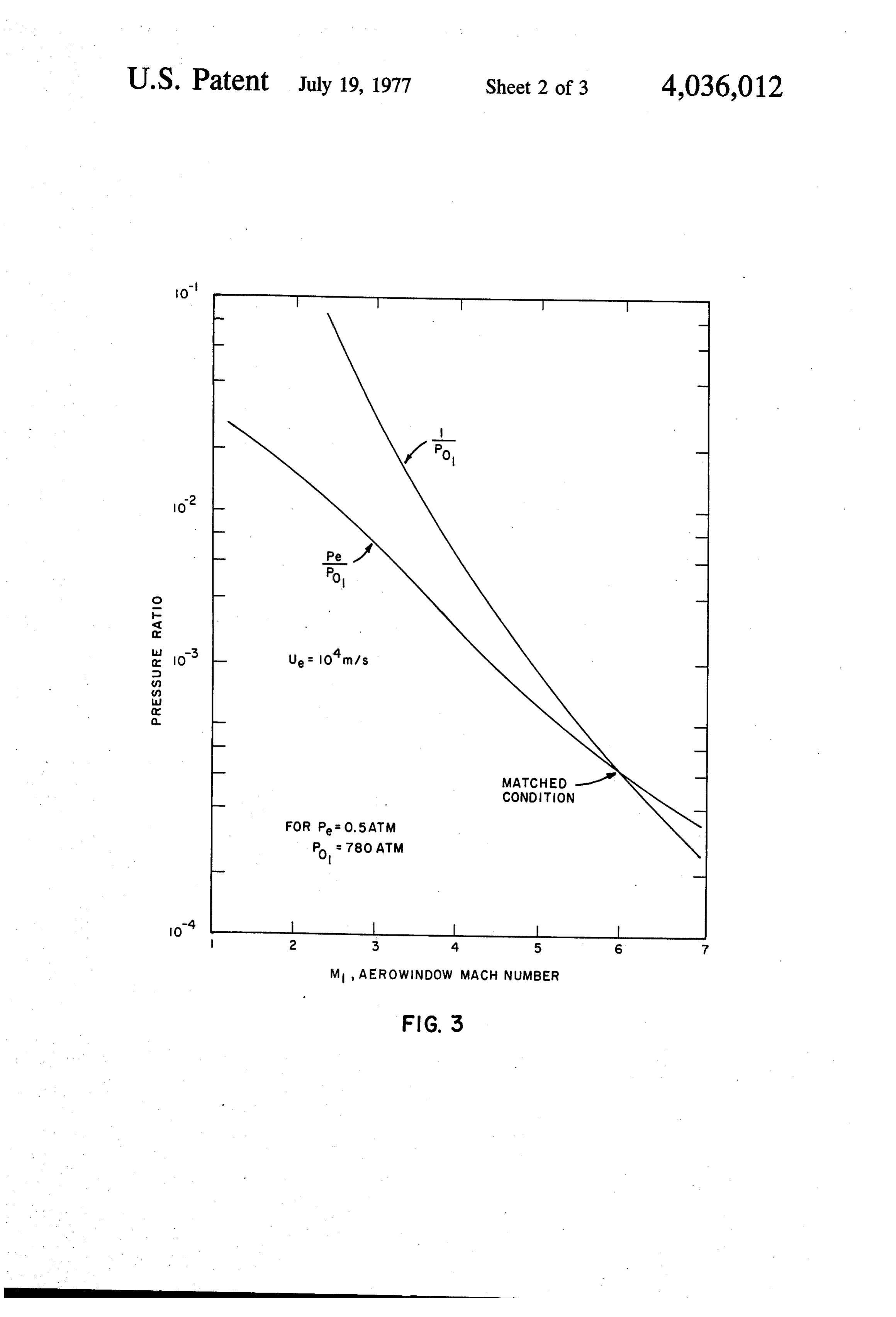
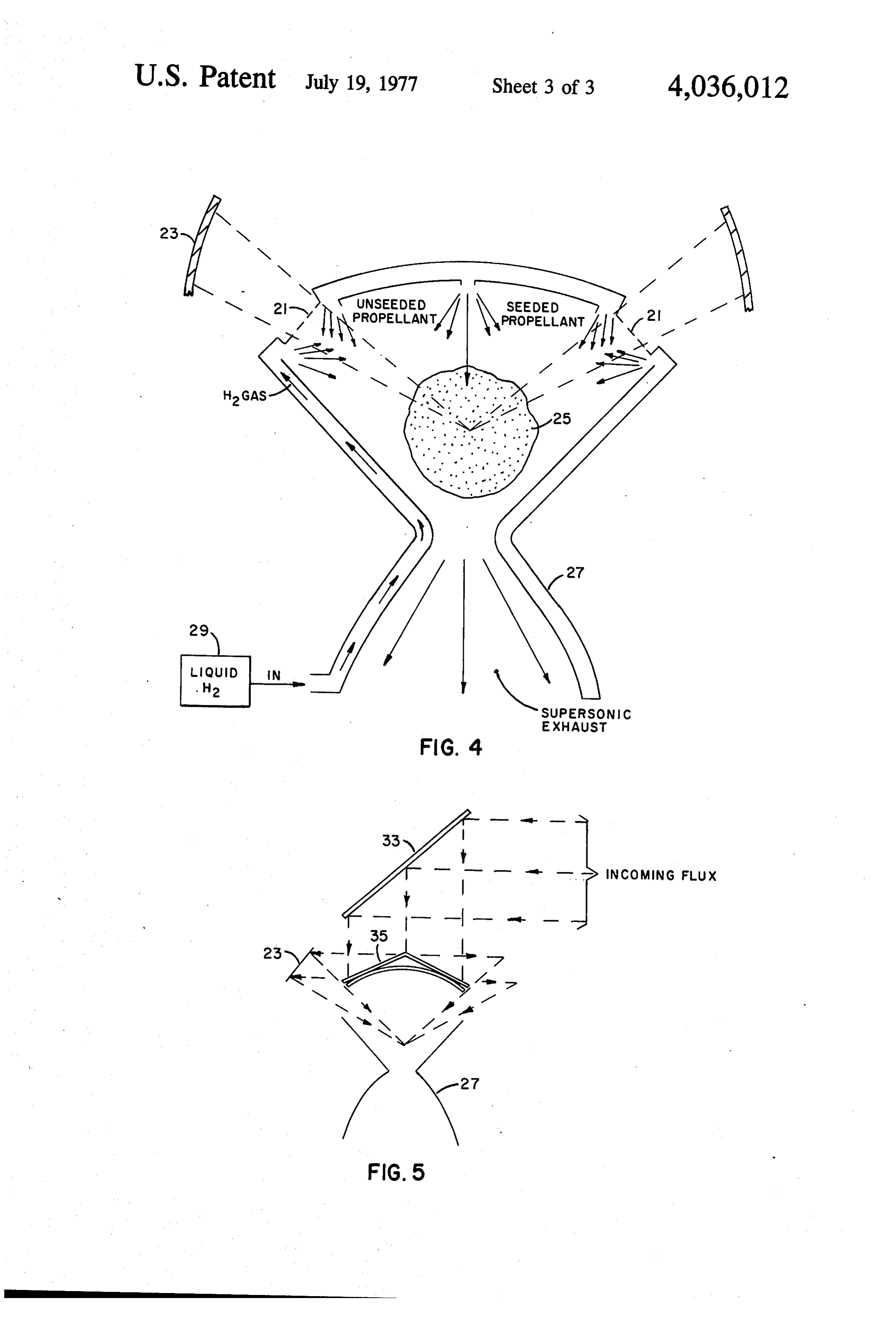
FIG. 1 is a showing of a parabolic nozzle rocket en specific impulse because absorption occurred in the gine; exhaust and shock waves formed which were opaque to FIG. 2 is a showing of a laser powered rocket engine radiation and which traveled up the laser beam. These utilizing the principles of the present invention; laser driven absorption waves prevented the radiation FIG. 3 is a graph of the pressure ratio versus the from reaching the desired absorption zone, and resulted Aerowindow Mach number; in very nonsteady and undesirable, inadequate perform FIG. 4 is a showing of a laser powered rocket engine 65 aC6.
in accordance with the present invention; and Clearly a method of decoupling the influx of radiation FIG. 5 is a showing of a configuration of optics for a from the outflux of exhaust gases is needed to positively laser powered rocket engine. avoid the formation and build up of these laser driven 6 absorption waves which interfere with the desired per are graphed against the window Mach number. Only formance of the engine. for one condition are the pressures equal and will the A second reason for searching for a way to separate rocket engine operate ideally (Mach 6 in the example). the influx of radiation from the outflow of exhaust gases A detailed version of the LPRE is shown in FIG. 4. is that many systems applications of laser propulsion are 5 The gasdynamic window 21 is around the upper perim difficult or impossible when burdened by the constraint eter of the chamber. The seedant is added in the center, that the exhaust vector always be aligned with the laser away from the annular window 21. An annular ring beam. For example, launching a satellite into earth orbit mirror 23 is provided for reflecting the laser beam from using one laser is impossible with the constraint of colin the ground source, not shown, through the gasdynamic ear thrust vector and laser beam and without auxiliary 10 window 21 to the absorption zone 25 where the seeded methods of propulsion. propellant absorbs the laser radiation and becomes a A window in the rocket stagnation chamber is an very hot gas which is fed through the rocket nozzle 27 obvious solution to the difficulty. Unfortunately the to create a supersonic exhaust to propell the missile. solid windows which are currently used to pass high The rocket nozzle is hollow and is fed liquid hydrogen power fluxes of laser radiation (>106 watts/cm2), such 15 from a source 29. As this hydrogen passes through the as crystals of salt or carbon, are either too small, too passageways in the nozzle it provides cooling of the weak mechanically, or too absorbant to consider for a throat and at the same time changes from liquid to gas LPRE of useful size. A useful size. LPRE would be which is combined with the propellant to provide an physically a meter in characteristic dimension and oper explosive or rapidly expanding mixer. The "seed' can ate at a laser power level of 109 watts, as a rough exam 20 be any of the well known "seeds' such as deuterium. ple. FIG. 5 shows a means for collecting the laser radia A window must not only transmit laser radiation at tion from the ground source and feeding it to the annu high flux level, it must be strong enough to withstand lar ring mirror 23. It consists of a rotatable collecting pressure differential across it equal to the chamber pres mirror 33 which is aligned with the incoming laser sure of the rocket engine, approximately 50-100 atmo 25 radiation by conventional means not shown. The laser spheres. A supersonic expansion of a gas can create these large pressure differences. All that is required is to radiation is reflected from the rotatable collecting mir onto dispersing mirror 35 which is an annular use a supersonic expansion as a laser window as well as cone shape mirror attached to the rocket nozzle 27. The the propellant inlet. The "seed' which is added to the laser radiation is reflected from mirror 35 onto the annu propellant to absorb the laser radiation is added after 30 lar ring mirror 23 and through the gasdynamic window. the window. The unseeded propellant, most likely hy I claim:
drogen or helium, is transparent to CO2 radiation at 10.6 1. A power system for a vehicle comprising: a nozzle u, when the gas is not ionized. A LPRE using such a gasdynamic expansion is shown in FIG. 2. This is a having pellant;
a heating chamber and an exhaust outlet; a pro first means for providing said propellant to said cylindrically symmetric rocket engine 5 which is pow heating chamber;
a gasdynamic window in said heating ered by an annular high power laser beam 7. The pro chamber; said gasdynamic window formed by second pellant inflow is on the central axis and comes in via a means which exhausts propellant at supersonic speed spider-like support which is not shown. The concentric across said window; laser radiation annular propellant pipes 9 and 10 carry unseeded pro through said gasdynamic window to saidbeing directed propellant for pellant in the outer pipe 9 and seeded propellant in the heating said propellant; said propellant having an un inner pipe 10. The propellant 11 is a very high pressure seeded portion which is transparent to the laser radia Po1 which causes the gas to expand rapidly in a super tion and a seeded portion which is opaque to said laser sonic (Prandtl-Meyer) expansion, causing the pressure radiation;
to drop by a very large factor to equal the ambient unseeded said second means directing the propellant's portion across said window; an absorption pressure P1 and forming the annular gasdynamic win 45 zone dow 12. The gas is then diffused down to a subsonic dow; inside said heating chamber remote from said win flow via shock waves, raising the static pressure. of theand third means for directing said seeded portion Seeded propellant 13 is added and the laser radiation is ferringpropellant with the to said absorption zone without inter laser radiation until reaching the ab absorbed in the absorption zone 15. The gas is then very sorption zone.
hot and at high pressure. The rocket nozzle 17 again 50 2. A system as set forth in claim 1 wherein said vehi creates a high velocity low pressure supersonic flow, the exit pressure of which P is tailored to equal the cle is a rocket; said nozzle being a rocket nozzle at tached to said rocket; a annuarring mirror attached to ambient pressure.
For a given rocket nozzle shape and desired specific said rocket so as to direct the laser radiation through impulse, there is one ideal condition at which the gasdy 55 said window to the absorption zone in a concentrated fashion; and other mirror means connected to said namic window can operate. The gas has to have a par rocket so as to direct said laser radiation to said annular ticular definite Mach number M or pressure ratio
(P/Poi) so as to have the inlet static pressure P and exit ring mirror.
3. A system as set forth in claim 2 wherein said rocket static pressure P exactly equal. The results of a typical calculation, omitting the details, is given in FIG. 3. The 60 nozzle said is hollow; liquid hydrogen being fed through hollow rocket nozzle so as to absorb the heat calculation was for a specific impulse of 103 seconds, equivalent to an exit velocity of 10 meters/sec. A gas of therein and convert the liquid hydrogen to a gas; fourth a ratio of specific heats of y = 1.4 was taken for conve means feeding the gas across said window to combine nience. An exit Mach number for the rocket nozzle of with said propellant; said window being annular in M = 3.0 was taken. For these conditions the pressure 65 portionshape; and said second means sending said unseeded ratio of the window expansion (P/Pol) and the nozzle of the propellant across the window being annu exit pressure ratioed to the supply stagnation pressure lar in shape. k it k . . . k. (P/Pol) which is dependent on the window expansion
Provenance
- Collection
- Patents citing this work
- Pages
- 6
- Method
- pdftotext (the PDF's own text layer) + pdftoppm 300dpi page scans
- Patent office record
- patents.google.com →
- Source
- Google Patents citing-documents table
- Assignee
- The United States Of America As Represented By The Secretary Of The Army
- Published
- 1977-07-19
- Transcribed from
- patentimages.storage.googleapis.com →