

patent · US4049535A
Electrical treater with a.c-d.c. electrical fields
20 September 1977
Text
Page 1bibliographic recordscan →
United States Patent (19)
Winslow, Jr.
(54 ELECTRICAL TREATER WITH AC-D.C.
ELECTRICAL FIELDS
75 Inventor: Joseph D. Winslow, Jr., Houston,
Tex.
Assignee: Petrolite Corporation, St. Louis, Mo.
Int. Cl. .............................................. C10G 33/02 52 U.S. C. .................................................... 204/305 Field of Search ................................ 204/305, 191
1,978,426 10/1934 Hahn ................................ 204/305 X 2,849,395 8/1958 Wintermute ......................... 204/305 3,252,884 5/1966 Martin et al. ..... ........ 204/302 3,772,180 1 1/1973 Prestridge ......... ... 204/305 3,847,775 11/1974 Prestridge............. ... 204/191 3,939,395 2/1976 Prestridge et al. ...................... 32.3/4
FOREIGN PATENT DOCUMENTS
Primary Examiner-John H. Mack
Assistant Examiner-Aaron Weisstuch
Attorney, Agent, or Firn-Sidney B. Ring; Hyman F.
Glass
An electrical field treater for resolving an emulsion formed of a continuous oil phase containing a dispersed water phase with grading a.c.-d.c. electric fields. The treater comprises a metal vessel having an emulsion inlet and outlets to remove the purified oil phase and a coalesced water phase. Insulated electrode sets are en ergized by an external power source to regulated d.c. potentials between the electrodes and earth ground, and an a.c. current component between the electrodes and earth ground. The earth ground may be a metal elec trode or a body of water maintained in the vessel. 12 Claims, 4 Drawing Figures
Drawings
Page 2drawing sheetscan →
Page 3scan →
separately by an a.c, power source and a d.c. power
ELECTRICAL TREATER WITH AC-D.C. source. However, it has been proposed to employ a ELECTRICAL FIELDS single power source with an electrical field treater to
Background of the invention
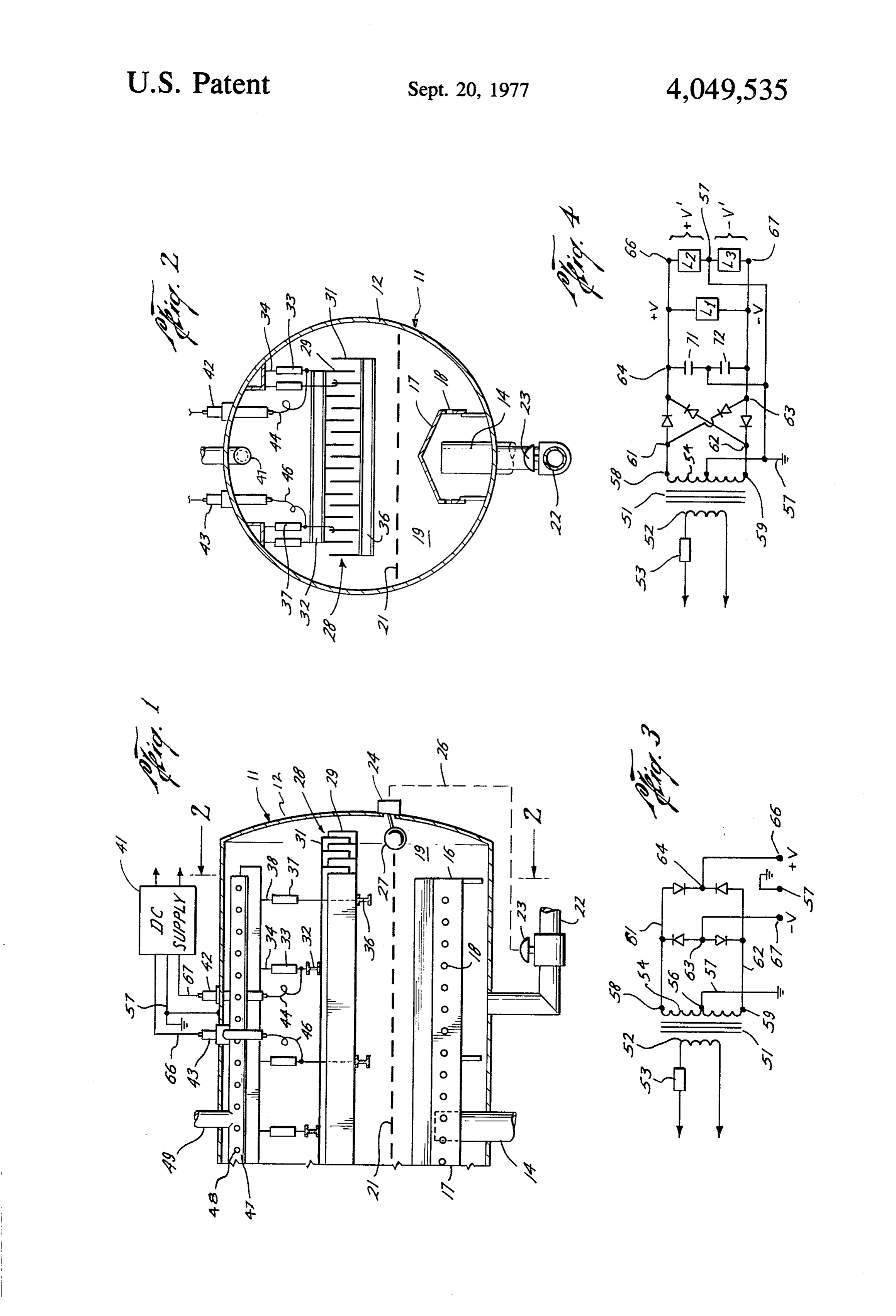
energize simultaneously sets of electrodes to a.c, and d.c. electric fields for emulsion resolution. In U.S. Pat, 1. Field of the Invention No. 2,849,395, there is shown an electrical field treater This invention relates to the resolving of emulsions for resolving an emulsion into a treated oil phase and a having a continuous oil phase containing a dispersed coalesced water phase using a.c.-d.c. electric fields, water phase. More particularly, the present invention Parallel, vertical metal plates are arranged within a relates to electrical field treatment for resolving water O metal vessel with one set of electrodes positioned up in-oil emulsions. stream for energization by an a.c. voltage and a down 2. Description of the Prior Art stream set of electrodes energized by a d.c. voltage, Electrical field treaters have been employed to re which preferably is pulsed. The metal vessel forms a solve emulsions for nearly 70 years. These emulsions subtended grounded electrode beneath these electrode have a continuous oil phase, which terminology in 15 sets. As a result, the grounded electrode (and any water cludes the various hydrocarbons such as crude oil, pe layer) of the vessel serves as a circuit common to both troleum distillates and residuum derived during refining a.c. and d.c. voltages. The power source provides si and other hydrocarbon processing. Also included in multaneously both d.c. and a.c. potentials on the elec this terminology are various organic liquid materials trodes relative to earth ground. The potential gradient which are water immiscible, have a relative low electri 20 (a.c. and d.c.) between electrodes in the upstream and cal conductivity and a low dielectric constant con downstream sets is uniform between adjacent elec pared to water. The dispersed water phase may be wa trodes in each set and also relative to the metal vessel ter, brine, or other aqueous material such as acids or which forms the circuit common reference. caustics. When the continuous phase is crude oil, the Attempts have been made to provide a common a.c.- treater usually employs an a.c. electric field for resolv 25 d.c. power source for energizing separate insulated ing the emulsion. A d.c electric field is preferable for electrode sets with an a.c. voltage component on elec resolving the dispersion where the continuous oil phase trodes upstream of the electrodes energized with a d.c. is a distillate and the dispersed water phase is an acid or voltage. For example, U.S. Pat. Nos. 3,772,180 and caustic. In other instances, it is desired to first apply an 3,847,775 illustrate an electrical field treater with a a.c. electric field to the emulsion, and then, subjecting 30 power source described as providing combined a.c.-d.c. the emulsion to a d.c. electric field to complete the potentials for energizing an insulated set of electrodes. treatment. Reference may be taken to U.S. Pat. No. The power source has a high voltage secondary wind 2,855,356 wherein there is described such a combination ing with one terminal at earth ground and the other a.c.-d.c. electrical field treater for resolving an emulsion terminal common to both electrode sets through half formed of distillate and an aqueous treating material. 35 wave rectifiers. If the current flow to the electrodes is More particularly, the electrical field treater is arranged of similar magnitudes, the system theoretically would for vertical flow of the emulsion and employs two sets be operable. However, a slight unbalance in the current of electrodes. The upstream set of electrodes is ener consumed by either electrode causes current within the gized by an a.c. potential and the downstream set of secondary winding of the transformer. Obviously, a d.c. electrodes is energized by d.c. potential. In addition, 40 current in the secondary winding of the transformer these a.c.-d.c. electric fields are arranged to provide causes magetization of the transformer core leading to potential gradients which change from non-uniform to increase in the primary current. This in turn will lead to uniform character in the direction of emulsion flow. In saturation of the current regulator preceding the trans this treater, each set of electrodes has one electrode former, and the primary overcurrent protection means energized and the other electrode referenced to ground 45 will most likely disconnect the power source from the for defining the electric field. A subsequent improve main supply. Thus, unbalance between the current ment is illustrated in U.S. Pat. No. 2,897,251 employing passed by the rectifiers to their respective loads will a dual output d.c. power source to provide two separate result in the necessity of disconnecting the source from d.c. potentials for energizing separate insulated sets of the main supply or require that components for regula electrodes, one electrode in each set being referenced to 50 tion and transformation be substantially underrated ground. A related combination of a.c.-d.c. electrical with respect to the normal treater loads. field treater is shown in U.S. Pat. No. 2,849,395. In this The full wave and half wave rectifying system em reference, a dual zone electrical field treater has an ployed in conventional power supplies has basically the upstream a.c. electric field zone with a following down same problem as in the aforementioned patents. Particu stream d.c. electric field zone for treating emulsions. In 55 larly, an unbalance in current consumption at the output particular, the d.c. zone employs a novel arrangement terminals causes an unbalanced a.c. component to be of planar, vertically-oriented, metal electrode sets, all of passed through one of the rectifiers. This a.c. compo which are insulated from the metal vessel and energized nent appears as a d.c. current in the secondary winding through separate entrance bushings from an external to magnetize the core of the transformer and results in power source. The external d.c. power source has a full 60 greater losses within the transformer, and leads to satu wave or half wave rectifier for producing the desired ration of conventional current limiting reactors. The d.c. electric field. In this instance, both electrodes are electrical field treater of the present invention provides energized relative to earth ground at a first potential a novel power supply which is capable of producing gradient, and the sets of electrodes are energized at a simultaneous energization of an insulated set of elec second potential relative to one another. 65 trodes with both a.c. and d.c. voltage components In the foregoing references, it is noted that the a.c. wherein the d.c. components are regulated at a first electric field and the d.c. electric fields for the com potential between the electrodes and at a second poten bined a.c.-d.c. electrical field treaters were provided tial relative to earth grounds in the treater. In addition, 4 either electrode can consume more current than the DESCRIPTION OF SPECIFIC EMBODIMENTS other, creating a substantially severe current unbalance and not magnetizing the transformer employed in the Referring now to FIGS. 1 and 2, there is an illustra power source. In addition, the magnitude of the a.c. tion of an electrial field treater 11 which includes a component present between the sets of electrodes and pressure vessel 12 having metal sidewalls and ends. The earth grounds is arranged to a selected value. vessel may be cylindrical with exterior insulation (not It is usual to employ current limiting reactors in the shown) and disposed with its longitudinal axis in the primary circuits of electric treater power sources. The horizontal. The treater 11 receives an emulsion through a pipe 14 into a distributor 16 which has a longitudinal transformers normally employed for full wave rectifica 10 section tion must be derated to approximately 35% output cur ably the17distributor carrying a plurality of openings 18. Prefer 16 is arranged in accordance with rent rating when supplying loads at half wave rectified U.S. Pat. No. 3,458,429. The emulsion should be uni d.c. The danger is that the regulator means will be set to formly discharged from the openings 18 into the vessel protect the transformer assuming balanced secondary 12. The dispersion passes upwardly through a body of operation, thus leaping to excessive (X3) overload op 15 water 19 which is maintained within the lower portion eration should one of the half wave d.c. load fields of the vessel 12. Then, the emulsion emerges from the collapse in the treater due to insulation failure or in interface 21 and moves into the a.c.-d.c. electric field creases in localized demand. established by electrode sets 28 carried about the mid SUMMARY OF THE INVENTION line of the vessel 12. The interface 21 of the body of 20 water 19 is held at a suitable horizon by the regulated
In accordance with the present invention, there is withdrawal of water through an outlet 22 in which flow provided an electrical field treater for resolving water is controlled by a motor valve 23. The motor valve 23 in-oil emulsions by grading a.c.-d.c. electrical fields. is actuated by controller 24 through an inner connection The treater system includes a vessel having an emulsion indicated by chain line 26. The controller 24 is operated inlet, an oil phase outlet and a water phase outlet. Elec 25 by a float 27 which monitors the horizon at which the trodes are mounted within the vessel in the flow path of interface 21 resides within the vessel 12. fluid moving between the inlet and oil phase outlet. The The electrode sets 28 are energized by a power source electrodes, which include first and second sets, are insu to produce an electric field with a.c. voltage compo lated from the vessel and adapted for simultaneous ener and nents between the interface 21 and these electrode sets, additionally, an electric field with d.c. voltage con gization by an external power source to d.c. potentials 30 ponents relative to each other and earth ground, and to a.c. between these electrode sets and the vessel 12 potential components above earth ground for resolving or other adjacent earth ground. As a result, the emul sion is subjected to grading a.c.-d.c. electric fields in the emulsion into a treated oil phase and a coalesced succession, and at non-uniform and uniform voltage water phase. The external power source includes a 35 gradients for resolution into the purified oil phase and power transformer connectable to an a.c. source of coalesced water phase. The electrode sets 28 may take current for providing elevated a.c. potentials at end any suitable form but preferably are arranged by mount terminals of a secondary winding in electrical isolation ing rigid planar metal electrodes 29 and 31 in a vertical to the a.c. source of current and earth ground. In addi orientation and aligned lengthwise parallel to the longi tion, the secondary winding has a center tap connected tudinal axis of the vessel 12. More particularly, the to earth ground and rectifiers forming a floating, full electrodes 29 and 31 can be equally spaced, longitudi wave bridge which is connected at opposite arm junc nally extending strips of metal equal in surface area tions to the end terminals of the secondary winding and disposed at substantially the middle line of the vessel 12. at the remaining arm junctions connected as positive The electrode sets 28 and 29 may thus have substantially and negative d.c. source terminals to the first and sec 45 the same surface area exposed for current flow to fluid ond sets of electrodes, respectively. A grounded elec within the vessel 12. The electrodes 29 are supported trode is disposed in spaced relationship from the first from transverse "I'beams 32 which are suspended from and second sets of electrodes. A body of treated oil is the vessel 12 by insulators 33 and support rods 34. The maintained about the first and second sets of electrodes electrodes 31 are mounted upon "I" beams 36 which are 50 suspended by insulators 37 from support rods 38 con by a control means, and this body of oil extends towards the grounded electrode. As a result, emulsion entering nected to the vessel 12, The electrodes 29 have bottom edges below electrodes 31 (as seen in FIG. 2), but both the vessel is subjected to grading a.c.-d.c. electrical electrodes fields during resolution and substantial unbalance of d.c. from a power are arranged separately for energization source 41 carried externally of the vessel current consumption in the first and second sets of elec 55 12. For this purpose, trodes fails to disrupt the a.c.-d.c. electric fields. entrance bushings 42 and 43 are provided through the sidewall of the vessel 12 with
DESCRIPTION OF THE DRAWINGS their lower terminals connected by leads 44 and 46, respectively, to electrodes 29 and 31. Externally of the
FIG. 1 is a partial vertical longitudinal section taken vessel 12, the bushings 42 and 43 connect respectively through an electrical field treater connected to a power 60 to the positive and negative d.c. potential terminals of source arranged according to one embodiment of the the power source 41. The earth ground 57 is connected present invention; between the power source 41 and the metal sidewall of FIG. 2 is a cross-section of the treater taken along line the vessel 12 to provide a "ground” reference for the 2-2 of FIG. 1; electrical system of the treater 11. FIG. 3 is an electrical diagram illustrating the basic 65 Energization of the electrodes 29 and 31 provides the elements of the power source shown in FIG. 1; and a.c.-d.c. combination electric fields for resolving the FIG. 4 is an electrical diagram illustrating the pre emulsion introduced through the pipe 14. The co ferred embodiment of the power source of FIG. 2. alesced water phase falls through the interface 21 and 5 merges into the body of water 19. The treated oil phase tive to ground 57. However, the load Li present be passes upwardly and is gathered into the collector 47 tween the electrodes 29 and 31 is referenced only be through the openings 48 and then it is moved through tween the terminals 66 and 67. As a result, the loads, Lt, an oil outlet pipe 49 from the vessel 12 to a suitable L2, and L3, can have different potential magnitudes and utilization. 5 different current demands, as long as the total current Refer to FIG. 3 for an illustration of the basic config consumption is within the capabilities of the trans uration for the power source 41 employed with the former 51. Irrespective of these different d.c. potentials present invention. A step-up transformer 51 has a center applied to these various loads, they can have different tap 56 connected to earth ground 57 for reference pur current demands. The function of the full wave floating poses. The end terminals 58 and 59 of the secondary 54 10 bridge and center tapped secondary 54 of the trans are connected to a full wave rectifier bridge. The trans former 51 permits a.c. components arising from unbal former 51 has a primary 52 connected through a control anced current demands to be returned through respec circuit 53 to suitable a.c. current sources which may be tive rectifers of the bridge so that the current flow a 220/440 volt circuit. The rectifier bridge is floating within the secondary 54, to each side of the center tap relative to earth ground and connects at opposite arm 15 56, remains balanced and free of d.c. current compo junctions 61 and 62 to terminals 58 and 59, respectively. lets.
The remaining arm junctions 63 and 64 connect to the The result is that any of all loads may be dropped, positive and negative d.c. source terminals 66 and 67 of shorted and/or combined without the need to consider the power source 41. The filtering capacitors of the dic what the effect might be on rating, disipation and/or supply source 41 have been omitted from FIG. 3 to 20 magnetization of the power source or supply compo simplify the present description. It will be apparent that nents. This system also exhibits 100% utility in the re the positive d.c. potential is present as a first voltage spect that process upsets which lead to collapse of the between terminals 57 and 66. A second voltage of equal fields within the treater can be sought out and corrected magnitude but of negative polarity is present between while maintaining power system continuity and pre terminals 57 and 67. Thus, the positive and negative 25 paredness for "picking up' the load when restored to potentials relative to earth ground 57 (at low current normal value.
demands) are essentially one-half of the a.c. potential In addition, the power source 41 provides a certain appearing between terminals 58 and 59 of the secondary magnitude of a.c. potential components between the 54. However, the full potential of the secondary 54 electrode sets 28 and earth ground 57 or the interface 21 between the terminals 58 and 59 appears as the d.c. 30 as the grounded electrode. For this purpose, capacitors potential component between the terminals 66 and 67. 71 and 72 are placed between the terminals 66 and 67 A current unbalance in either the positive or negative and earth ground 57 at the arm junctions 63 and 64 of terminal of the power source 41 will return the resulting the full wave bridge rectifiers. These capacitors are a.c. component through the other arm of the rectifier selected to have reactances inducing a certain magni bridge into the secondary 54 between one of terminals 35 tude of "ripple' in the d.c. voltage --V and - V ac 58 or 59, and earth ground 57 (terminal 56). For exam cording to conventional design criterions. The trans ple, should the terminal 66 pass more current than the former 51 operates generally from 60 Hz a.c. power terminal 67, an a.c. component is returned into the sec sources so that the output voltage at arm junctions 63 ondary 54 between the terminals 56 and 59 to exactly and 64 has a ripple frequency of 120 Hz. The capacitors balance the current demand of the secondary 54 be are selected so that a certain "ripple' is obtained which tween terminals 56 and 58. As a result, no d.c. current is the Rms value of the a.c. potential component relative components can appear in the secondary 54 of the trans to the total d.c. output across load L1. For example, former 51. Thus, either of the d.c. potential output ter these capacitors are selected so that there is at least minals 66 and 67 can provide a separate d.c. potential about a 5% ripple in the d.c. current at the terminals 66 and current flow relative to ground 57 and the secon 45 and 67. Thus, if the d.c. potential between the terminals dary 54 is immune from the deleterious effects of unbal 66 and 67 is 50kv d.c., then the a.c. component between ance current consumption in the treater 11. In accor these terminals relative to earth ground will be 2.5 kV. dance with the present invention, the power source 41 is As a result, the a.c. potential field of 2.5 kv is applied arranged so that there is an a.c. component which also between the electrode sets 28 and the interface 21 or is present between the terminals 66 and 67 relative to 50 other related "grounded' electrode inerposed between earth ground 57. the electodes and the incoming emulsion, i.e., upstream In reference to FIG. 4, the preferred embodiment of from said electrode sets 28, relative to the direction of power source 41 of FIG. 3 is illustrated with like com flow of the emulsion. Preferably, this grounded elec ponents bearing like numerals. The floating full wave trode structure is horizontal relative to the vessel 12. rectifier bridge has been redrawn to illustrate graphi 55 It will be apparent that the power source 41 provides cally the return path of a.c. potential components when a unique energization of the electrical field treater 11. If an unbalance in current appears at the output terminals desired, the electrodes 29 and 31 may be energized to 66 and 67 relative to earth ground 57. The terminals 66 the same d.c. potential, one being negative and one and 67 connect to the electrodes 29 and 31, respectively. being positive, relative to earth ground. Alternatively, The electrodes 29 have a current demand indicated as 60 the d.c. potentials of energization of these electrodes load L2; the electrodes 31 have a current demand indi may be adjusted to a different magnitude or so that both cated as load Li; both loads being relative to earth electrodes consume identical current. Thus, the opera ground 57. The current demand (a.c. and d.c.) between tor of the electrical field treater 11 may determine the electrodes 29 and 31 is indicated as load L. The whether he wants to treat by uniform potential gradi load L1 is energized by d.c. potentials --V and - V, and 65 ents or uniform current demand in the d.c. field between the loads L2 and L3 by +V' and - V'respectively. the electrodes 29 and 31 and also to earth ground 57. It will be apparent that the voltages +V' and - V' are In summary, the power source 41 permits insulated both referenced between the terminals 66 and 67 rela electrodes to be selectively energized to positive and 6 negative d.c. potentials of selected magnitudes and cur 2. The electrical treater system of claim 1 wherein rent demands, whether equal or different, and to pro said grounded electrode is disposed horizontally within vide an a.c. potential component between the electrodes said vessel means, and ground. Also, the transformer 51 may be used at its 3. The electrical treater system of claim 1 wherein full rated current capacity even if current demands by 5 said control means for maintaining said body of treated the loads are varied. Thus, the d.c. potential and current oil phase is adapted to provide an oil phase-water phase demand of each of electrodes 29 or 31 is separate and interface as said grounded electrode. apart from the other, and the a.c. component can be 4. The electrical treater system of claim 1 wherein selected irrespective of the d.c. potentials and current said first and second sets of electrodes are provided by demands. A single power source provides a plurality of O at least a pair of parallel rigid planar metal electrodes d.c. potentials and currents, and a.c, potential compo mounted vertically in said vessel means, nents and currents, separately from one another without 5. The electrical treater system of claim 1 wherein interference, and without any danger of a current unbal said first and second sets of electrodes have substan ance destroying the utility of the power source 41. tially the same surface area exposed for current flow to From the foregoing, it will be apparent that there has fluid within said vessel means.
been provided a novel electric field treater employing a 6. The electrical treater system of claim 1 wherein single unitary supply source capable of energizing elec said first and second sets of electrodes are provided by plurality of equally-spaced parallel straight metal trodes with both d.c. and a.c. potentials and unbalanced plates mounted vertically in a supporting framework currents in a manner not previously found in the arts. 20 suspended by insulators
Various changes and modifications may be made to the said plates are positionedwithin said vessel means, and alternately between said first structure of the present electric field treater without and second sets of electrodes whereby uniform gradient departing from the spirit of the invention. It is intended d.c. electrical fields exist between that the present description be taken in illustration of nonuniform a.c.-d.c. electrical fieldsadjacent plates and exist between the the present invention, the appended claims define the 25 edges of said plates and said grounded electrode. scope of the present invention. 7. The electrical treater system of claim 1 wherein What is claimed is:
said full wave rectifier bridge outputs to said positive 1. An electrical treater system for resolving water-in and negative oil emulsion by grading a.c.-d.c. electrical fields, com able voltage potential terminals have separately adjust capabilities whereby d.c. current unbal prising: 30 ance in demand between said first and second sets of a vessel means having emulsion inlet means, and oil electrodes and earth ground can occur without effect phase and water phase outlet means; ing changes in elevated d.c. potentials applied thereto. b. electrode means mounted within said vessel means arranged to be in the flow path of fluid moving d.c.8. potentials
The electrical treater system of claim 7 wherein applied to said first and second sets of between said emulsion inlet means and oil phase 35 electrodes can be selected independently from the total outlet means, and said electrode means including d.c. potential applied between said first and second sets first and second sets of electrodes insulated from . of electrodes.
said vessel means and adapted for simultaneous 9. An electrical treater system for resolving water-in energization by an external power source to d.c. oil emulsion by grading a.c.-d.c. electrical fields, com potentials relative to each other and a.c. potential 40 prising:
components above ground for resolving the emul a. vessel means having emulsion inlet means, oil phase sion into a treated oil phase and a coalesced water outlet means and water phase outlet means; phase; b. electrode means mounted within said vessel means c. said external power source including power trans including first and second sets of electrodes insu former means connectable to an a.c. source of cur 45 lated from said vessel means and ground, and a rent for providing elevated a.c. potentials at end grounded electrode disposed in spaced relationship terminals of a secondary in electrical isolation to the to said sets of electrodes and arranged to be up a.c. source of current and earth ground, and said stream from said sets of electrodes relative to the secondary having a center tap connected to earth direction of flow of the emulsion; ground with a floating full wave rectifier bridge 50 c. said first and second sets of electrodes provided connected at opposite arm junctions to the end with electrical bushing means and conductors for terminals of said secondary and at the remaining simultaneous energization by an external power arm junctions as positive and negative d.c. source source to elevated d.c. potentials; and terminals to said first and second sets of electrodes, d. an external power source providing elevated d.c. respectively; 55 potentials to said first and second sets of electrodes d. said electrode means including a grounded elec at substantially the same potential magnitude rela trode disposed in spaced relations to said first and tive to ground but opposite in d.c. polarity, and also second sets of electrodes and arranged to be up providing at least about a 5% ripple in the d.c. stream from said sets of electrodes relative to the current between said first and second sets of elec direction of flow of the emulsion; and trodes and an a.c. voltage component between said e. control means for maintaining a body of treated oil sets of electrodes and ground, said a.c. voltage com phase about said first and second sets of electrodes ponent being a percentage of the d.c. voltage be and extending toward said grounded electrode, tween said first and second sets of electrodes, said whereby emulsion within said vessel means is sub percentage being the same as the percent of ripple jected to grading a.c.-d.c. electrical fields during 65 in said d.c. voltage; whereby emulsion within said resolution and substantial unbalance in d.c. current vessel means is subjected to grading a.c.-d.c. electri demand in said first and second sets of electrodes cal fields during resolution and substantial unbal fails to disrupt the a.c.-d.c. electrical fields. ance in d.c. current demands in said first and second 7 sets of electrodes fails to disrupt the a.c.-d.c. electri 11. The electrical treater system of claim 10 wherein cal fields. said secondary has a grounded center tap wherein said 10. The electrical treater system of claim 9 wherein full wave bridge outputs to said positive and negative potentials have separate voltage capabilities whereby said d.c. power source includes a power transformer 5 d.c. current unbalance between said first and second means energized by a.c. current and having elevated a.c. potentials at end terminals of a secondary in electri sets of electrodes and earth ground produces no simul taneous change in elevated d.c. potentials applied cal isolation to the a.c. source of current and earth thereto.
ground, rectifier means comprising a floating full wave 12. The electrical treater system of claim 10 wherein bridge circuit connected at opposite arm junctions to 10 d.c. potentials applied in said first and second sets of the end terminals of said secondary and at the remaining electrodes can be regulated independently from the arm junctions as positive and negative d.c. source termi total d.c. potential applied between said first and second nals to said first and second sets of electrodes, respec sets of electrodes. s s k st tively.
Provenance
- Collection
- Patents citing this work
- Pages
- 7
- Method
- pdftotext (the PDF's own text layer) + pdftoppm 300dpi page scans
- Patent office record
- patents.google.com →
- Source
- Google Patents citing-documents table
- Assignee
- Petrolite Corporation
- Published
- 1977-09-20
- Transcribed from
- patentimages.storage.googleapis.com →