

patent · US4061463A
Combustion system and method
6 December 1977
Text
Page 1bibliographic recordscan →
United States Patent (19)
Bennett
54 COMBUSTION SYSTEM AND METHOD
Inventor: Henry J. Bennett, Palos Park, Ill.
73 Assignee: Burdett Manufacturing Company,
Bridgeview, Ill.
51 Int. Cl’............................................... F23M 9/06 52 U.S.C. .......................................... 431/9; 431/11;
(58) Field of Search ................... 431/9, 115, 116, 285,
2,688,360 9/1954 Haynes et al. ....................... 431/115 3,146,821 9/1964 Wuetig .......... ... 431/15 3,361,183 1/1968 Reichhelm .... ... 431/16 3,620,657 11/1971 . Robinson ................................. 431/9
3,705,784 12/1972 Reichhelm et al. .................. 431/16 Primary Examiner-Edward G. Favors
Attorney, Agent, or Firm-Allegretti, Newitt, Witcoff & McAndrews
A combustion system and method for liquid fuels in cludes atomizing the liquid fuel, withdrawing heated air from an enclosure which is to be heated by the fuel, contacting the atomized liquid fuel with the heated air which is at a temperature sufficient to instantaneously vaporize the fuel and in a quantity sufficient to form a combustible mixture with the vaporized fuel, and burn ing the combustible mixture to heat the enclosure. In addition, a dual fuel system is disclosed which is capable of using either the aforementioned liquid fuel system and method or a natural gas combustible mixture.
13 Claims, 1 Drawing Figure
M7 varia
Drawings
Page 2drawing sheetscan →
Page 3scan →
countered in the first described system, it is essentially
COMBUSTION SYSTEMAND METHOD still as uneconomical, cumbersome and space consum ing as the first described system. In addition, special
BACKGROUND OF THE INVENTION burners are needed in the air heating chamber because This invention relates to a combustion system and of the elevated pressures in that chamber. method and, more particularly, to a combustion system Systems have also been employed in the past in an and method utilizing heated air from an enclosure attempt to improve economy. These systems, by and which is to be heated to form a combustible mixture for large, have utilized economizers or heat exchangers for heating the enclosure. transferring some of the sensible heat from the flue Both liquid and gaseous fuel systems are widely used O gases escaping from the oven or enclosure to the air in industry for the heating of processing chambers, such which forms the combustible mixture. Although such as drying and curing ovens. These systems generally fall economizers or heat exchangers do improve the econ into one of two broad categories. One category includes omy of the system, they are cumbersome, expensive, the nozzle mixing systems in which the fuel is intro and space consuming.
duced through the burner tip where it is then mixed at 15 The present invention overcomes each of the above the burner with air supplied from a separate source, mentioned disadvantages. The present invention is eco such as a blower, to form a combustible mixture which nomical, not only from the standpoint of improved ignites at the burner. The second category is the premix heat-to-fuel ratios, but also from the standpoint of re type of system in which a combustible mixture of air or duced initial capital expenditure, reduction of auxiliary other oxidizing gas is mixed with the fuel before reach 20 equipment and reduction in space comsumption. The ing the burner and this mixture is pressurized and dis present invention may be readily adapted to the dual use charged from the burner where it ignites. Burners such of alternate fuels of different kinds and phase states in as infrared burners are within the last category, as is the the event that one of the fuels becomes unavailable and present invention. the need for shutdown or changing burners, such as Several premix systems have been employed in the 25 infrared burners, which are otherwise not compatible past which utilize liquid fuels, such as No. 1 and No. 2 with both gas and liquid fuels is avoided. The combus fuel oils. One such system includes an oil superheating tion system and method of the present invention are safe device which includes a tank having liquid fuel oil and minimize explosion hazard. Specially designed aux therein. An auxiliary burner is located in the tank to iliary burners need not be employed in the present in heat the oil and form oil vapors. The vapors are drawn 30 vention, since the auxiliary burners need not discharge from the tank by a Venturi or other vacuum mixing against a back-pressure. Finally, the present invention device and cold air, at ambient room temperature, is may be easily retrofited on existing installations. blown through the Venturi where the vaporized oil and In one principal aspect of the present invention, a air are mixed to form the combustible mixture. This combustion system which is adapted to heat an enclo mixture is then conducted to the burners where it is 35 sure includes combustion burner means for supplying burned. " . heat to the enclosure, conduit means connected to the That system suffers several disadvantages. One disad burner means for supplying a combustible mixture of an vantage is that the room temperature air in the combus oxidizing gas and a fuel to the burner means, injection tible mixture consumes sensible heat upon ignition of means for discharging a finely atomized liquid fuel to the mixture, thus resulting in low efficiency and econ 40 the conduit means, second conduit means between the omy. Another disadvantage is that the system is cum enclosure and the first conduit means for supplying bersome and requires the provision of substantial quan heated oxidizing gas from the enclosure to the first tities of auxiliary equipment which is both expensive conduit means adjacent the injection means, and control and space consuming. Another significant disadvantage means for controlling the temperature and quantity of is that of safety, since the auxiliary burners which are the oxidizing gas supplied from the enclosure such that employed to heat the oil to vaporize it always present the oxidizing gas vaporizes the liquid fuel atomized by the possibility of explosion of the vapors. In addition, the injection means and forms a combustible mixture. since the vapors are mixed with air which is only at In another principal aspect of the present invention, a ambient temperature, condensation of the oil may occur method of heating an enclosure includes the steps of in the piping and at the burners which produces soot. SO elevating the temperature of the enclosure, forming an Such soot requires frequent cleaning, reduces efficiency atomized liquid fuel, removing a portion of an oxidizing and may damage the articles being treated in the oven. gas from the heated enclosure, contacting the atomized Moreover, the condensation of the oil prevents the use liquid fuel with the heated oxidizing gas, controlling the of infrared burners which are only operable with gase quantity and temperature of the gas removed from the ous fuels and frequently necessitates a change of burners 55 enclosure so as to form a combustible mixture with the where both liquid and gaseous fuels must be used on fuel and vaporize the atomized liquid, and burning the different occasions. mixture to heat the enclosure. Another system employs an air heating chamber These and other objects, features and advantages of which also contains an auxiliary burner. Air at ambient the present invention will be more clearly understood room temperature is injected under pressure into the air through a consideration of the following detailed de heating chamber where its temperature is elevated by scription.
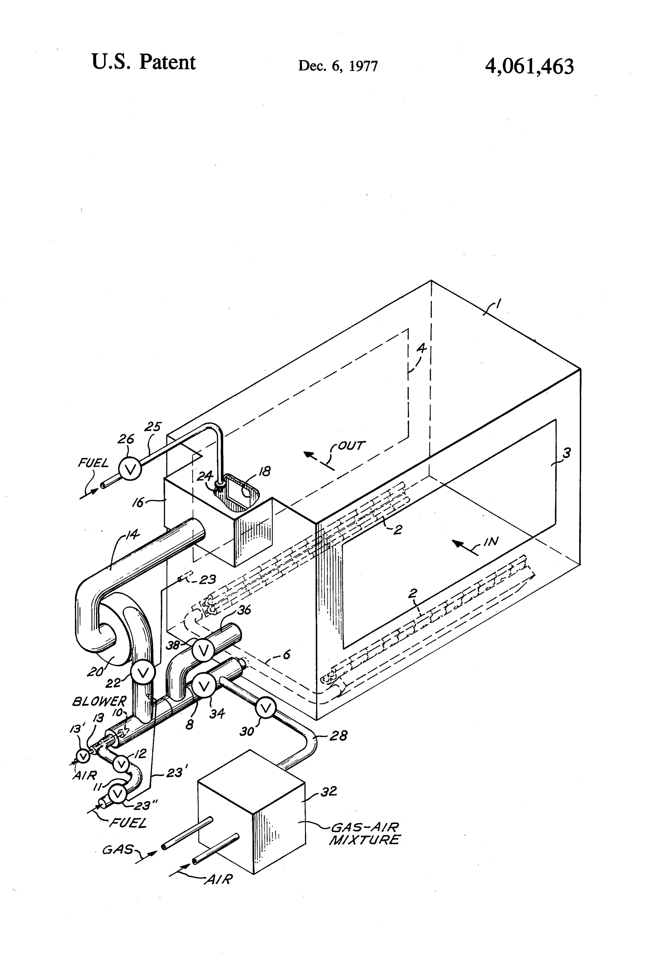
the auxiliary burner to a temperature substantially in excess of the dew point of the liquid-fuel. This heated air BRIEF DESCRIPTION OF THE DRAWING is then brought into contact with atomized liquid fuel to In the course of this description, reference will fre vaporize the fuel and form a combustible mixture which 65 quently be made to the attached drawing in which the is burned at the burners. - sole FIGURE is an overall schematic view of a combus Although the latter system, to a major extent, solves tion system and a system which employs the method the safety and condensation and sooting problems en incorporating the principles of the present invention.
Page 4scan →
mixture, but at a temperature sufficiently above the dew
Description of the preferred
EMBODIMENT point of the atomized liquid fuel to insure instantaneous vaporization of the fuel, not only at the time of mixing,
An overall schematic view is shown in the drawing of but at the time of discharge from the burners 2. a preferred embodiment of combustion system and The quantity of gases passing through conduit 14 may method which incorporates the principles of the present be controlled in any well-known manner, such as by invention. The system and method of the present inven way of a suitable valve 22 between blower 20 and con tion, as shown in the drawing, are utilized in the heating duit 8. Valve 22 is preferably controlled by means of a of an enclosure 1, such as an industrial processing cham temperature sensor 23 which senses the temperature in ber, drying or curing oven having premix burners 2 for 10 enclosure 1 and controls valve 22 to adjust the pressure heating the enclosure. The enclosure may include suit and volume of hot gases delivered from blower 20 to able entrance and exit apertures 3 and 4 through which conduit 8 in accordance with the heat demand of the articles to be treated are conveyed into and out of the enclosure. In turn, the fuel flow rate through nozzle 10 enclosure by suitable conveyor means (not shown). is adjusted in response to the pressure in conduit 14 The burners may comprise one or more of a wide 15 between valve 22 and conduit 8 by a pressure transmit variety of premix burners, although infrared burners are ting conduit 23' which is connected to a flow control preferred because of their cleanliness and efficiency. In valve 23' in the fuel line 11.
addition, infrared burners are preferred, since liquid fuel The dew point of No. 1 and No. 2 fuel oils is approxi flames such as fuel oil as contemplated in the present mately 200-300' F. Thus, the oxidizing gas, which is invention, are more susceptible to flame quenching than 20 usually air, gas flames. Upon quenching, soot is produced which is in conduit 8which should is mixed with the atomized liquid fuel exceed that temperature and should detrimental to industrial finishes and other heating pro preferably exceed 400 cesses. Infrared burners minimize the possibility of be vaporized upon exitFfrom to insure that the fuel will still the burners 2 to prevent flame quenching, since combustion occurs against an incandescent surface of the burner which is generally at 25 any condensation of the fuel before it reaches the burn a temperature of 1600" F to 2500' F, well above the ers. If the temperature of the gases in the enclosure 1 will exceed 400 F during normal operation, auxiliary quenching temperature.
The burners 2 are connected to a suitable manifold 6 temperature elevating burners or the like in conduit 14 will through which a combustible mixture of fuel and an ing initial be unnecessary during continuing operation. Dur oxidizing gas, preferably air, is conducted to the burn 30 gases passingheat-up, however, it is necessary to heat the es. . . through conduit 14, since the gases from A premix fuel assembly is positioned outside, but only. the enclosure at light-off will be at room temperature adjacent to, one of the walls of the enclosure. The pre For this purpose, an auxiliary burner 24 is posi mix assembly includes a first conduit 8 having a tee tioned in the chamber 16 which may be used during which communicates at one end with the manifold 6. 35 light-off to elevate the temperature of the gases passing One or more liquid fuel injection nozzles 10 are posi into conduit 14 to a temperature sufficiently above the tioned in the other end of the conduit 8 and are con dew point of the fuel being used to insure vaporization nected, by a suitable fuel line 11 and shut off and balanc of the fuel. In the event that the normal operating tem ing valve 12, to a source of liquid fuel supply (not peratures in enclosure 1 do not exceed a temperature shown) such as No. 1 or No. 2 fuel oil. In addition, a sufficient to insure that the dew point of the liquid fuel compressed air conduit 13 is preferably provided hav will be exceeded at the nozzle 10, the auxiliary burner ing shut off valve 13' which connects a source of com 24 will be energized as necessary during continuing pressed air (not shown) to the nozzle 10 to atomize the operation to insure that the proper temperature of the liquid fuel at the nozzle. Although the liquid fuel may gas is maintained in conduit 14.
be injected under pressure without air from conduit 13, Burner 24 is connected to a suitable fuel supply (not the air-liquid nozzle is preferred because such nozzle is shown) by way of conduit 25 and valve 26. If space is at capable of producing a more uniform atomization over a premium, it will be understood that chamber 16 may wide variations in fuel flow rates as ignition is varied to be eliminated and burner 24 may be located directly in control the heat demands of enclosure 1, conduit 14. It should be noted that auxiliary burner 24 A second conduit 14 is mounted so as to remove need not be of special design, since it discharges to heated gases from the top of the enclosure 1 and intro essentially atmospheric pressure.
duce the heated gases to the liquid fuel which has been The present invention may be readily adapted to dual atomized by nozzles 10. Conduit 14 may either commu fuel use which is desirable where certain fuels may nicate directly with the enclosure 1 or, preferably, by become scarce during certain seasons of the year. For way of an auxiliary chamber 16 as shown in the draw 55 example, during most of the year it may be preferred to ing. Chamber 16 opens to the top of enclosure 1 through burn a natural gas-air mixture at burners 2. However, an aperture 18 in the enclosure wall. A blower 20, pref. during some seasons and in certain geographical loca erably of the centrifugal, constant pressure delivery tions, natural gas supplies may become critical andd it type, is located in condiut 14 so as to take suction on the would be desirable to be able to easily shift to a liquid chamber 16 and discharge the gases at a pressure of 60 fuel oil supply, without shutdown of the oven. preferably about 16-32 osig to intimately mix the heated One such dual fuel system is shown in the drawing. gases drawn from enclosure 1 with the atomized fuel. The system includes a gas-air injection system including It is the purpose of the present invention to form a a conduit 28 having a shut-off valve 30 which communi pressurized combustible mixture for burning at the cates with conduit 8 between manifold 6 and nozzle 10. burners 2 by mixing the atomized liquid fuel injected 65 A combustible natural gas mixture is formed at 32 by through nozzle 10 with the hot gases from conduit 14. any suitable apparatus familiar to those skilled in the art Thus, the gases from conduit 14 should be present, not and the mixture is led through conduit 28, conduit 8 and only in a sufficient quantity to form the combustible manifold 6 to the burners. 2.
Page 5scan →
A valve 34 is located in conduit 8 between condit 28 the invention. Numerous modifications may be made by and nozzle 10 so that the liquid fuel system previously those skilled in the art without departing from the true described may be isolated and inactivated when the spirit and scope of the invention. natural gas-air mixture is being burned. In addition, a What is claimed is:
by-pass conduit 36, having a valve 38, communicates 5 1. A combustion system adapted to heat an enclosure, between the enclosure 1 and conduit 8 at location be said system comprising: . .
tween valve 34 and conduit 14. The purpose of the combustion burner means for supplying heat to said by-pass conduit is to preheat the liquid fuel system prior enclosure, . to changover from natural gas to liquid fuel. first conduit means connected to said burner means It is believed that the foregoing description of the 10 for supplying a combustible mixture of an oxidizing system of the present invention is sufficient to under gas and fuel to said burner means, stand the operation of the invention. However, the injection means for discharging finely atomized liquid operation will be briefly described as follows. fuel to said first conduit means, ! The system may be initially lit off on either the natu second conduit means between said enclosure and ral gas or liquid fuel systems, the latter utilizing burner 15 : said first conduit means for supplying heated oxi 24, as previously described. dizing gas from said enclosure to said first conduit It will first be assumed for further description of the means adjacent said injection means, operation that light off has been completed, that enclo control means for controlling the temperature and sure 1 has reached its desired temperature, and that the quantity of the oxidizing gas supplied from said burners 2 are in operation and burning a mixture of 20 second conduit means such that the oxidizing gas natural gas and air. In this condition, valves 12, 13' and vaporizes the liquid fuel atomized by the injection 34 are closed and valve 30 is opened. Gas and air are means and forms said combustible mixture, and mixed at 32 in quantities sufficient to form a combustible heating means for supplying additional heat to the gas mixture and that mixture is conducted under pressure passing from said enclosure to said second conduit through conduit 28, open valve 30, conduit 8 and mani 25 3S.
fold 6 to the burners 2 where it is burned. 2. The system of claim 1 wherein said control means It will now be assumed that it is desired to shift from includes said heating means.
natural gas operation to liquid fuel. Prior to shifting, 3. The system of claim 1 wherein said control means valves 22 and 38 are opened and blower 20 is energized. includes valve means in said second conduit means for The blower 20 will draw gases which are already 30 controlling the quantity of gas passing through said heated by the still functioning natural gas system from second conduit.
enclosure 1 through aperture 18, chamber 16 and valve 4. The system of claim 1, wherein said heating means 22 and will discharge these heated gases into the nozzle comprises at least one combustion burner. area of conduit 8 and through open valve 38 and con 5. The system of claim 1 wherein said combustion duit 36 back to the enclosure. These heated gases will 35 burner means comprise infrared burners. preheat conduit 14 and its blower 20 and the atomizing 6. The system of claim 1 including pumping means in section of conduit 8 of the liquid fuel system in prepara said second conduit means.
tion for changeover. 7. A combustion system adapted to heat an enclosure, After a few minutes, valves 30 and 38 are shut and said system comprising:
valves 12, 13' and 34 opened. In this condition, liquid 40 combustion burner means for supplying heat to said fuel from fuel line 11 will now be atomized at nozzle 10, enclosure, instantaneously vaporized by the heated gases from first conduit means connected to said burner means conduit 14, and mixed with a sufficient quantity of the for supplying a combustible mixture of an oxidizing gases under pressure from blower 20 to form a combus gas and fuel to said burner means, tible mixture which passes through conduit 8 and mani 45. injection means for discharging finely atomized liquid fold 6 to the burners 2 where it is burned. fuel to said first conduit means, Changeover from liquid fuel operation to natural gas second conduit means between said enclosure and is essentially the reverse of the operation just described. said first conduit means for supplying heated oxi To changeover to gas, valves 12, 13 and 34 are shut and dizing gas from said enclosure to said first conduit valve 30 is opened. 50 means adjacent said injection means, It will be seen from the above description that the first control means for controlling the temperature present invention is quite economical, since the oxidiz and quantity of the oxidizing gas supplied from said ing gases which are used to form the combustible mix second conduit means such that the oxidizing gas ture are gases which have already been heated by waste vaporizes the liquid fuel atomized by the injection heat from the system. Moreover, the need for elaborate, 55 means and forms said combustible mixture, cumbersome, expensive and space consuming equip second injection means for injecting a combustible ment is minimized and possible safety hazards are mixture of a second fuel and an oxidizing gas into avoided. It will be seen that the system is easily capable said first conduit means, and of utilizing dual fuels of differing nature and change second control means for selectively supplying either over may be accomplished without placing the equip 60 the combustible mixture of the first mentioned fuel ment out of operation and without changing burners, or the second mentioned fuel to the burner means. and infrared burners may be used with the liquid fuels 8. The system of claim 7 including pumping means in which could not otherwise be used with such fuels. said second conduit means, wherein said control means Moreover, the present invention is capable of easy ret includes valve means in said second conduit means for rofit on existing installations. 65 controlling the quantity of gas passing through said It will be understood that the embodiment of the second conduit and at least one combustion burner present invention which has been described is merely means for supplying additional heat to the gas passing illustrative of one of the applications of the principles of from said enclosure to said second conduit means.
Page 6scan →
9. The system of claim 7 wherein said second injec forming an atomized liquid fuel, tion means injects said combustible mixture into said removing a portion of an oxidizing gas from said first conduit means between the first mentioned injec heated enclosure, tion means and said burner means. contacting said atomized liquid fuel with said heated 10. The system of claim 7 including third conduit oxidizing gas, means for supplying heated gas from said enclosure said oxidizing gas being further heated before contact through said second conduit when said second men with said atomized liquid fuel, controlling the quantity and temperature of the gas tioned fuel is being supplied to said burner means. removed from said enclosure so as to form a com 11. The system of claim 8 including third conduit 10 bustible mixture with said fuel and vaporize said means for supplying heated gas from said enclosure to atomized liquid fuel, and said second conduit when said second mentioned fuel is burning said combustible mixture to heat said enclo being supplied to said burner means. S.
12. A method of heating an enclosure comprising the 13. The method of claim 12 wherein said oxidizing steps of: 15 gas is air.
elevating the temperature of the enclosure,
Provenance
- Collection
- Patents citing this work
- Pages
- 6
- Method
- pdftotext (the PDF's own text layer) + pdftoppm 300dpi page scans
- Patent office record
- patents.google.com →
- Source
- Google Patents citing-documents table
- Assignee
- Burdett Manufacturing Company
- Published
- 1977-12-06
- Transcribed from
- patentimages.storage.googleapis.com →