

patent · US4071004A
Electro-static fuel mixture system
31 January 1978
Text
Page 1bibliographic recordscan →
United States Patent (19)
Ostergaard
SYSTEM
76 Inventor: Neil A. Ostergaard, 3830 S. 43rd St.,
Apt. 10, Milwaukee, Wis. 53220
(51) Int. Cl’............................................. FO2M 27/04 52 U.S. Cl. ................................................. 123/119 E 58 Field of Search .................................... 123/119 E
1,333,838 3/1920 Csanyi .............................. 123/119 E
2,839,037 6/1958 McKeever ... 123/119 E 2,999,485 9/1961 Lundy ............... ... 123/119 3,476,095 11/1969 De Laubarede ..... ... 123/119 3,682,608 8/1972 Hicks ............................... 123/119 E 3,753,304 8/1973 Hughes ............................ 123/19 E 3,761,062 9/1973 King.......... ... 123/119 E 3,955,548 5/1976 Thomas..... ... 123/119 E 3,963,408 6/1976 Youngberg ... ... 123/119 E 3,980,053 9/1976 Horvath ........ ... 123/119 E 3,989,017 11/1976 Reece ............................... 123/119 E
Primary Examiner-Charles J. Myhre
Assistant Examiner-David D. Reynolds
Attorney, Agent, or Firm-Clarence A. O'Brien; Harvey
B. Jacobson
The air and fuel induction passage of a combustion engine is provided with air filtering structure for filter ing the air entering the induction passage and fuel inlet structure for admitting fuel into the induction passage downstream from the air filtering structure. A forami nous panel constructed of conductive material is insula tively supported from the air filtering structure and
disposed for passage of at least substantially all of the air moving through the air filtering structure through the foraminous panel. The fuel inlet structure includes at least a portion thereof constructed of conductive mate rial and a source of high voltage, low amperage current is electrically connected, to the foraminous panel on one side and to the conductive portion of the fuel inlet structure on the other side.
6 Claims, 2 Drawing Figures
2 disf7zo CAP WA-52 so
Drawings
Page 2drawing sheetscan →
Page 3scan →
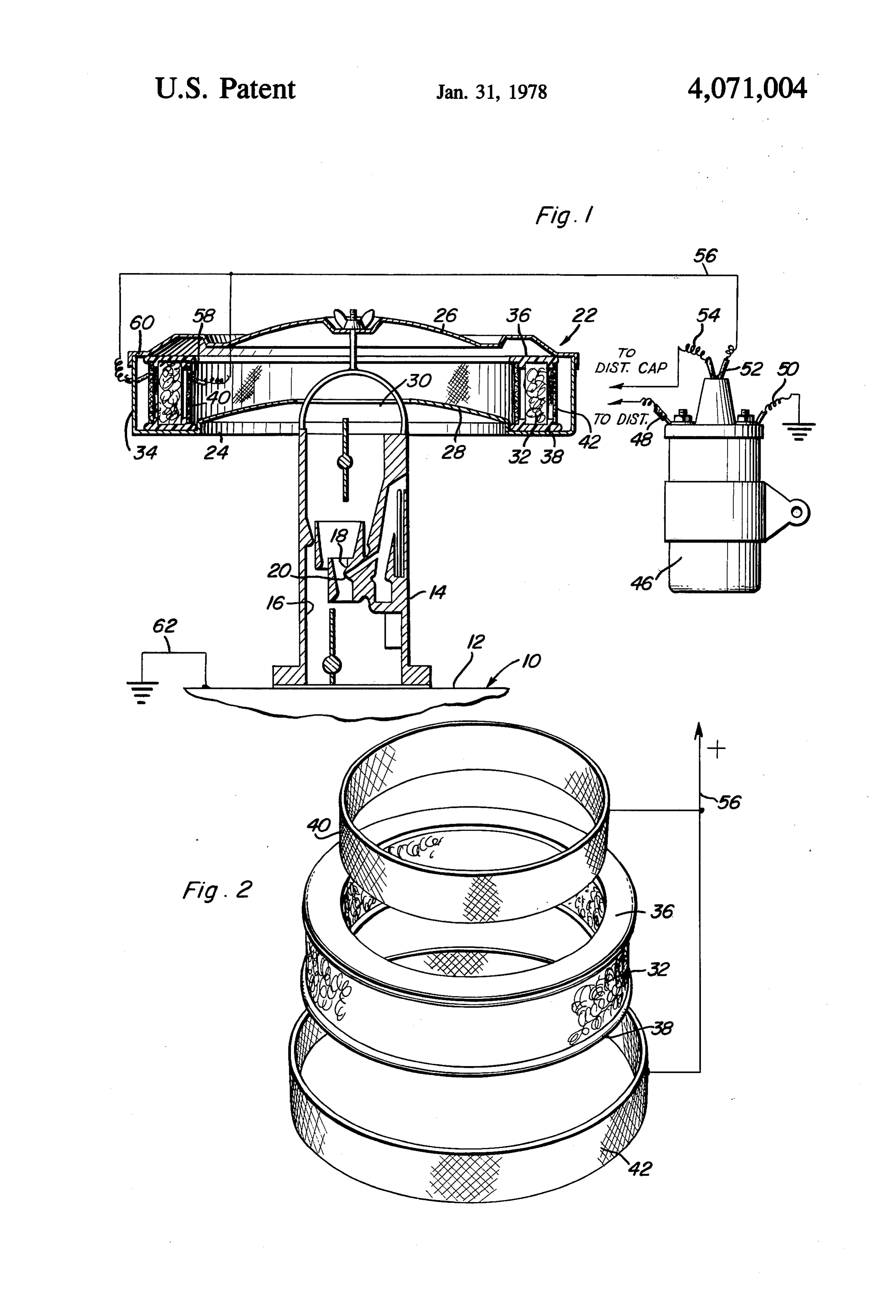
ELECTRO-STATC FUELMIXTURE SYSTEM BRIEF DESCRIPTION OF THE DRAWINGS FIG. 1 is a vertical sectional view taken substantially
BACKGROUND OF THE INVENTION upon a center plane passing through the air and fuel Recently there has been renewed attemps to increase 5 induction system of a conventional automotive-type the efficiency of internal combustion engines of the type combustion engine and with the conductive foraminous which conventionally power motor vehicles in order air charging panels of the instant invention operatively that these engines may afford greater fuel mileage. connected to the secondary voltage of the ignition coil One method pursued in increasing the fuel economy 10 of the associated combustion engine; and FIG. 2 is an exploded perspective view of the air of an internal combustion engine is to provide structure filtering body and inner and outer foraminous panels to whereby the air entering the induction passage of the be operatively engine may be electrically charged, either negatively or housing. associated therewith within the air filter positively, and the fuel discharged into the induction passage may be electrically charged either positively or 15 DETAILED DESCRIPTION OF THE negatively, respectively. By subjecting the air and fuel INVENTION with opposite charges and thus ionizing the initial mix Referring now more specifically to the drawings, the ture of air and fuel, the tendency of the fuel to mix more numeral 10 generally designates a conventional form of thoroughly with the air is increased so as to result in a internal combustion engine utilized to propel present more readily combustible mixture. 20 day motor vehicles. The engine 10 includes an intake The examples of apparatuses previously designed for manifold 12 having a carburetor 14 mounted thereon. this purpose are disclosed in U.S. Pat. Nos. 1,873,746, The intake manifold 12 and carburetor 14 are con 2,839,037, 3,110,294,3,266,783, 3,476,095, 3,537,829 and structed of metal and are thus electrically conductive. 3,761,062. The carburetor 14 defines an air and fuel induction 25 passage 16 extending therethrough and the lower outlet
BRIEF DESCRIPTION OF THE INVENTION end of the passage 16 opens into the manifold 12 in a Conventional automotive combustion engine air fil conventional manner. The carburetor 14 includes an tering systems utilize an annular air filtering body and electrically conductive portion 18 thereof through the instant invention provides a pair of inner and outer 30 which liquid fuels such as gasoline is discharged as at 20 axially short cylindrical foraminous panels for dispo into the passage 16 and the inlet end of the passage 16 sition immediately inwardly and outwardly of the annu has an air filter assembly referred to in general by the lar air filtering body and with the foraminous panels reference numeral 22 operatively associated therewith. insulatively supported from the air filter structure from The air filter assembly 22 includes a circular housing 24 having vertically spaced top and bottom walls 26 and 28 which the annular air filtering body is supported. A 35 and the bottom wall 28 has a central opening 30 formed source of secondary voltage from the ignition coil of the associated vehicle is electrically connected on one side therein from which air entering the air filter assembly pass into the inlet end of the passage 16. The air to the inner and outer foraminous panels and the ground filter assembly terminal of the primary circuit of the ignition coil is filtering body 3222ofisannularprovided with a conventional air configuration and sealingly grounded to the engine and thus the carburetor thereof 40 supported between the top and bottom walls 26 and 28 which admits fuels into the induction passage of the adjacent the outer peripheral portion thereof. The hous engine. In this manner, the foraminous panels are elec ing 24 includes an outer peripheral cylindrical wall 34 trically connected to one side of the high voltage, low spaced outwardly of the air filtering body 32 and ex amperage current source and the associated carburetor tending between the top wall 26 and the bottom wall 28, comprises a ground for that source. 45 the outer peripheral wall 34 having an air inlet opening The main object of this invention is to provide a (not shown) formed therethrough as is conventional. means for oppositely electrically charging the air and The air filtering body 32 is conventionally supported fuel passing through a conventional air and fuel charge between upper and resilient dielectric annular members forming device of a combustion engine. 36 and 38 and the instant invention includes a pair of A further object of this invention is to provide an 50 inner and outer foraminous axially short cylindrical apparatus in accordance with the preceding objects and panels 40 and 42 supported between corresponding which is adapted to utilize the secondary current output inner and outer peripheral portions of the dielectric and a conventional ignition coil as the required source panelsannular members 36 and 38 whereby the foraminous of high voltage, low amperage current. 40 and 42 are insulatively supported from the air filtering assembly 22, the panels 40 and 42 being con
A final object of this invention to be specifically enu 55 structed of conductive material.
merated herein is to provide an apparatus in accordance The engine 10 includes an ignition system including a with the preceding objects and which will conform to conventional ignition conventional forms of manufacture, be of simple con its primary side, to acoil 46 electrically connected, on struction and easy to install so as to provide a device electrical potential as at 48 and source suitable grounded (not shown) of as at 50. The that will be economically feasible, long lasting and rela source of electrical potential for the coil 46 comprises tively trouble free in operation. the conventional storage battery of the associated These together with other objects and advantages motor vehicle and the battery is electrically connected which will become subsequently apparent reside in the to the coil 46 through the conventional distributor of details of construction and operation as more fully here 65 the engine 10.
inafter described and claimed, reference being had to The coil 46 includes a secondary current output 52 the accompanying drawings forming a part hereof, connected by a conductor 54 to the center electrode of wherein like numerals refer to like parts throughout. the center of the cap of the aforementioned distributor 4 and also by conductor 56 to the inner and outer panels 1. In combination with a combustion engine of the 40 and 42 as at 58 and 60, respectively. The engine 10 is type including induction passage for air and fuel includ grounded as at 62 to a ground common with the ground ing air filtering means operatively associated with its 50. If desired the conductor 56 may be connected di inlet end and fuel inlet means for admitting fuel into said rectly to the panel 42 at 60 and a second conductor may induction passage downstream from said air filtering be used to electrically connect the panel 42 to panel 40. means intermediate the inlet end of the induction pas Accordingly, the inner and outer panels 40 and 42 are sage and the outlet end thereof opening into said engine, electrically connected to a source of high voltage, low foraminous panel means constructed of conductive ma amperage current and the air passing through the air O terial means insulatively supported from said air filtering and disposed for passage of at least substantially filter assembly 22 is forced to pass not only through the annular body 32 but also through the cylindrical forami all of the air passing through said air filtering means nous panels 40 and 42 and is thereby electrically through said foraminous panel means, said fuel inlet means including at least a fuel discharging portion charged, at least to some degrees, by the panels 40 and thereof 42. On the other hand, the carbaretor, and specifically 15 voltage, constructed of conductive material, and high the portion 18, is grounded as at 62 to the common cally connected to said current low amperage source means, electri foraminous panel means and ground for the coil 46. Accordingly, fuel being dis grounded relative to said fuel inlet means fuel discharg charged as at 20 into the passage 16 is oppositely ing portion.
charged and more complete mixture of the liquid fuel 2. The combination of claim 1 wherein said current discharged into the passage 16 with air passing through 20 source means comprises the secondary voltage source the air filter assembly 22 and subsequently through the of an induction coil having its primary side electrically passage 16 is increased due to ionization of the air and connected to a suitable source of electrical potential. fuel, the air having attained one electrical charge and 3. The combination of claim 1 wherein said combus the fuel having attained the opposite electrical charge. tion engine includes an ignition system to which sec The more efficient mixing of air and liquid fuel within 25 ondary spark voltage is supplied from said secondary the passage 16 results in more complete combustion of voltage source.
the air and fuel mixture within the engine 10 and thus 4. The combination of claim 3 wherein said air filter results in increased fuel economy of the engine 10. If it ing means includes means defining an annular air intake is desired, the panels 40 and 42 may receive their electri passage radially of which air passing through said air cal charge from an ignition type of vibrator coil in lieu 30 filtering means passes, said air filtering means includes of the coil 46. However, the loss of current by the elec an annular air filtering body concentrically disposed in trical connection of the output 52 to the panels 40 and said air intake passage, said foraminous panel means 42 is minimal and does not adversely affect the ignition includes an axially short cylindrical panel concentri system of the engine 10. cally disposed relative to said annular air filtering body. The foregoing is considered as illustrative only of the 35 5. The combination of claim 4 wherein said cylindri principles of the invention. Further, since numerous cal panel is disposed outwardly of said air filtering modifications and changes will readily occur to those body.
skilled in the art, it is not desired to limit the invention 6. The combination of claim 4 wherein said forami to the exact construction and operation shown and nous panel means includes a second axially short cylin described, and accordingly all suitable modifications drical panel concentrically disposed relative to said and equivalents may be resorted to, falling within the annular body, said cylindrical panels being disposed scope of the invention. outwardly and inwardly of said air filtering body. What is claimed as new as follows:
Provenance
- Collection
- Patents citing this work
- Pages
- 4
- Method
- pdftotext (the PDF's own text layer) + pdftoppm 300dpi page scans
- Patent office record
- patents.google.com →
- Source
- Google Patents citing-documents table
- Assignee
- Ostergaard Neil A
- Published
- 1978-01-31
- Transcribed from
- patentimages.storage.googleapis.com →