

patent · US4075519A
Brushless alternator
21 February 1978
Text
Page 1bibliographic recordscan →
United States Patent (19)
Mircun
(54) BRUSHLESS ALTERNATOR
Inventor: yugOSaV1a,
Mr. Shova 4, Domzale,
30 Foreign Application Priority Data 74 Yugoslavi 2819/74
Nov. 22, 1974 ligOSlavia . . . . . . . . . . . . . . . . . . . . . . . . . . .
52 U.S. C. ................................... 310/67 R; 310/263
: 8% Sw: - - -- - - - - - - - - - - - - - - - - O - 36/67 35iiso. 6/970 SEM soa e so ovo v a sa o e o evows ov v ovo310/263 3.535,566 10/1976 Smith. ... 30/266 3,610,979 10/1971 Thomas. ... 310/263 3,783,313 1/1974 Mathur................................... 310/67
FOREIGN PATENT DOCUMENTS
158,333 10/1963 U.S.S.R. ............................... 310/263 Primary Examiner-R. Skudy
Attorney, Agent, or Firm-Karl F. Ross
An electrical machine, especially an alternator, has a housing axially split into two generally symmetrical
the halvestwoinhousing which ahalves rotor shaft is journaled. Held between are parts of stator teeth which coact with two relatively offset sets of rotor poles mounted on the shaft, the teeth being interconnected
inside or outside the rotor by an annular magnetic yoke. A stationary excitation coil, surrounding a split inner hub of the rotor body, is carried within the rotor by the yoke or by a tooth-supported ring to generate a flux magnetizing the poles. The teeth have wings closely spaced from the orbital paths of the poles and also have webs, about half as wide as their wing span, enveloped by armature windings in which the output voltage of the alternator is induced upon a turning of the rotor.
10 Claims, 6 Drawing Figures
Drawings
Page 2drawing sheetscan →
Page 3drawing sheetscan →
Page 4drawing sheetscan →
Page 5scan →
The cross-bar of each tooth advantageously includes
BRUSHLESS ALTERNATOR a radially extending web surrounded by the associated
Field of the invention
armature winding and a pair of wings extending later ally from this web adjacent the pole pieces, a preferred
The present invention relates to an electrical ma wing span being about twice the width of the web as measured in the axial direction. The spacing of the teeth chine, more particularly an alternator of the brushless type. with reference to that of the pole pieces and the electri
Background of the inventon
cal interconnection of the armature depends, of course, on the desired type of output voltage (e.g. single-phase
Conventional alternators, in which slip rings and O or three-phase) as is well known per se. contact brushes are used to deliver the generated output Although reference will be made only to an alterna voltage from a rotating armature winding to a load or to tor in the following description, it will be apparent that energize an excitation coil of a rotating electromagnet, an analogous construction may be adopted for an elec are subject to various disadvantages such as noise, sensi tric motor.
tivity to dust and oxidizing atmospheric conditions, and 5 BRIEF DESCRIPTION OF THE DRAWING sparking which makes such machines unsuitable for use in explosive atmospheres. The same drawbacks exist in now The above and other features of my invention will electric motors provided with such slip rings and panying be described in detail with reference to the accom brushes. drawing in which:
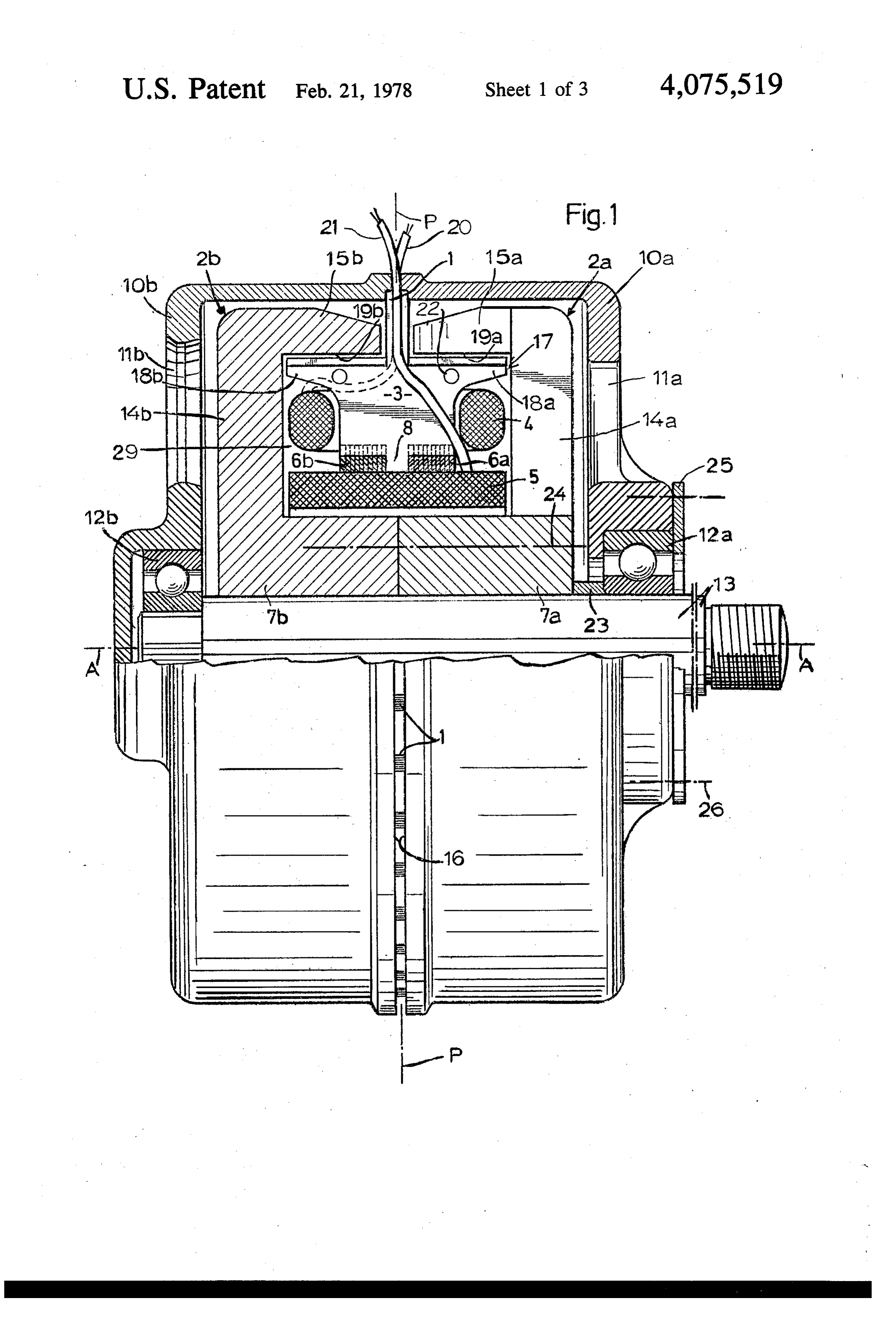
20 FIG. 1 is an elevational view, partly in axial section,
OBJECTS OF THE INVENTION of an alternator embodying my invention;
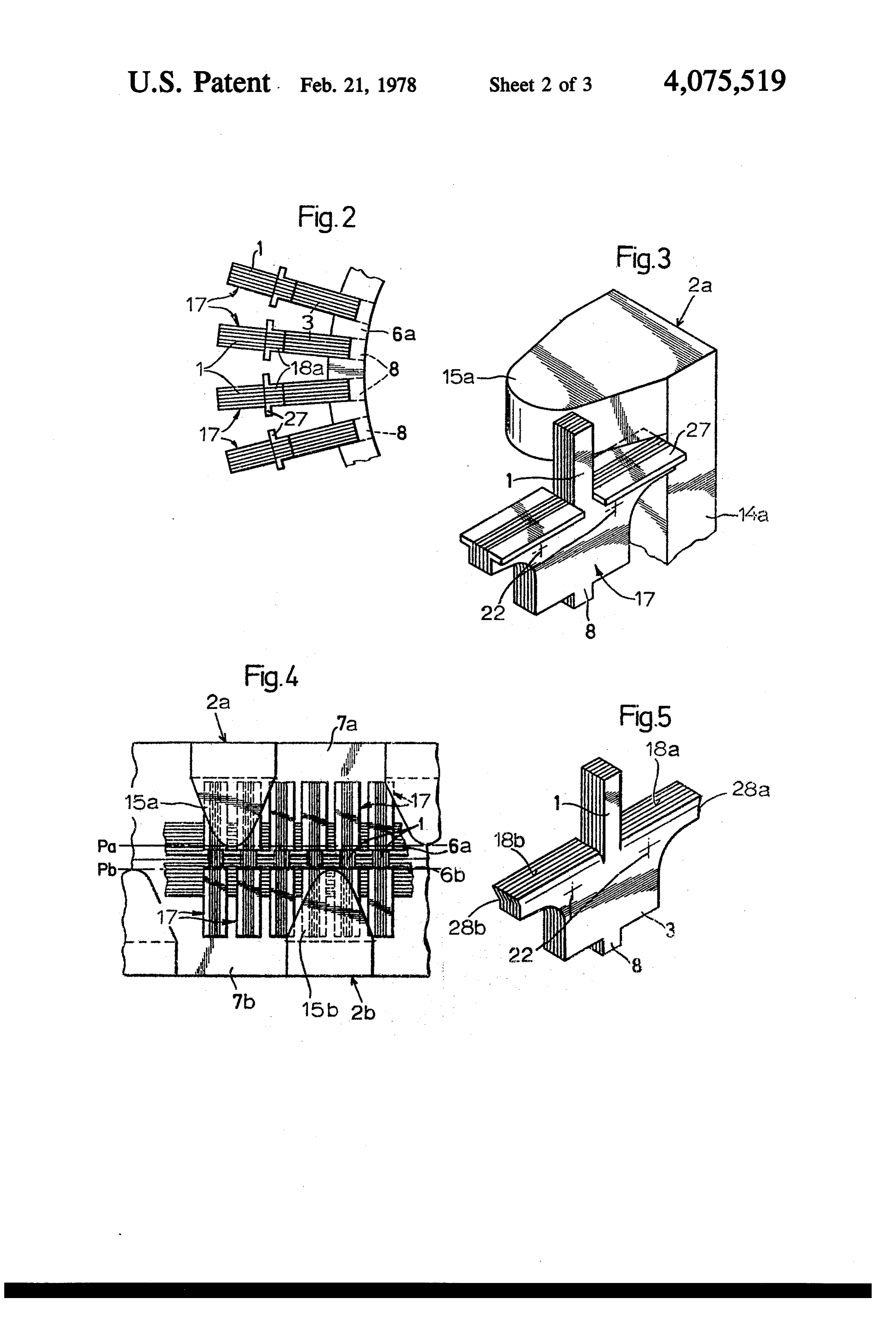
The general object of my present invention, there FIG. 2 is a fragmentary side view of a stator, with fore, is to provide an improved electrical machine of the inwindings removed, forming part of the machine shown brushless type which is of simple construction and obvi 25 FIG.FIG. 1;
ates the aforestated disadvantages. 3 is a fragmentary axonometric view of a stator A more particular object is to provide an alternator, tooth and a rotor pole piece included in the alternator of of either the single-phase or the three-phase type, hav FIG. 1;
ing a higher power output than conventional alternators andFIG. 4 is a fragmentary developed view of the rotor the stator of the alternator of FIG. 1;
of comparable weight and dimensions. 30 FIG. 5 is a view similar to FIG. 3, showing a modi SUMMARY OF THE INVENTION fied tooth; and
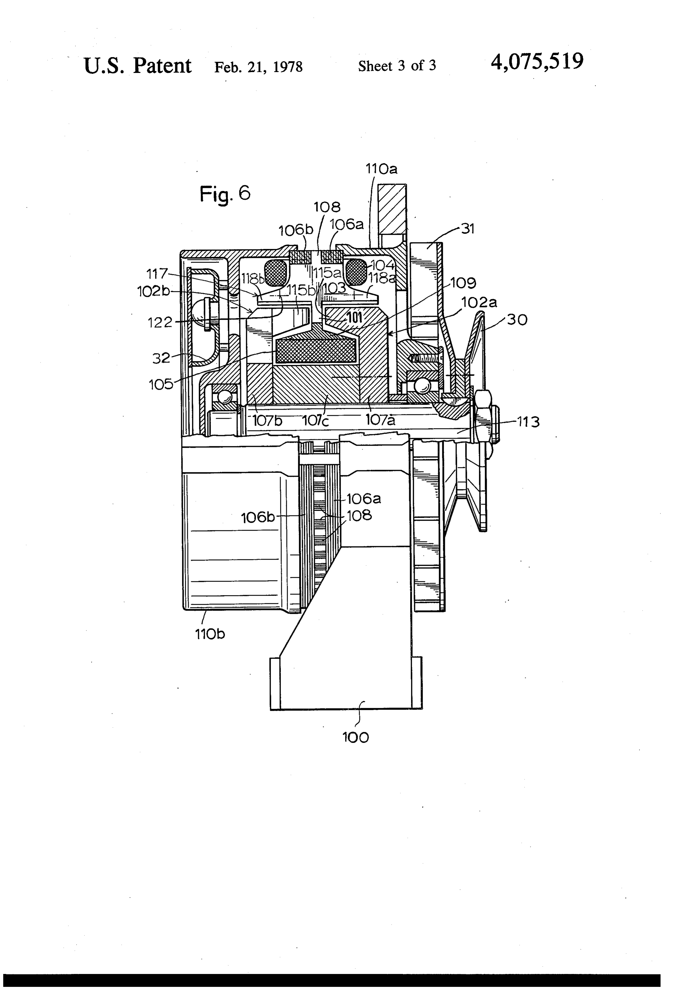
An electrical machine according to my present inven embodiment FIG. 6 is a view similar to FIG. 1, illustrating another tion comprises two relatively rotatable members cen of my invention. tered on a common axis, one of these members (referred 35 SPECIFIC DESCRIPTION to hereinafter as the rotor) having a magnetically per In FIG. 1 I have shown an alternator, i.e. an electrical meable body which includes a magnetized central hub machine for the generation of an alternating voltage, whose extremities are rigid with two axially spaced comprising a substantially cylindrical housing split into annular arrays of pole pieces; the pole pieces of one two generally mirror-symmetrical halves 10a, 10b array, having substantially axially extending faces on formed with venting apertures 11a, 11b. Journaled in one side of a transverse midplane, are peripherally offset this housing, by means of ball bearings 12a and 12b, is a from the oppositely polarized pole pieces of the other rotor shaft 13 with a threaded end adapted to receive a array which have substantially axially extending faces pulley 30 (see FIG. 6) driven from an external prime on the opposite side of that midplane. The other mem mover not shown. The shaft may also carry a fan 31 for ber, referred to hereinafter as the stator, is also magneti 45 blowing cooling air through the apertures 11a and 11b cally permeable and includes a set of peripherally as likewise illustrated in FIG. 6.
spaced generally T-shaped teeth which carry armature Shaft 13 carries a rotor split into two substantially windings and are positioned for magnetic interaction identical but relatively offset halves, comprising a hub with the pole pieces, the teeth being mechanically and 7a, 7b whose extremities are integral with radially ex magnetically interconnected by an annular yoke cen 50 tending arms 14a, 14b of generally L-shaped pole pieces tered on the axis. Unless the hub is formed in whole or 2a, 2b having axially disposed cheeks 15a, 15b which in part by a permanent magnet, its magnetization is terminate short of a transverse midplane P, as do the maintained by a stationary excitation coil concentrically two housing halves 10a and 10b. Seated within a gap 16 surrounding it with intervening spacing, that coil being between these housing halves, and fastened thereto by supported on the stator. 55 soldering or other suitable means, are radially out In accordance with an important feature of my inven wardly extending stems 1 of a set of generally T-shaped tion, the "T" of each tooth has a stem passing radially teeth 17 which pass between the two peripheral arrays along the aforementioned midplane between the two of pole pieces 2a and 2b into an annular space 29 de arrays of pole pieces and an axially extending cross-bar fined by the pole pieces and the hub, the cross-bar of the positioned to pass close by the substantially axially ex "T" having the shape of a web 3 of substantially greater tending faces of these pole pieces upon relative rotation width than the stem 1 as measured in the direction of a of the two members, either outside or inside the rotor. central axis A. Laterally extending wings 18a, 18b inte The latter arrangement, in which the major tooth por gral with web 3 have a span substantially twice the axial tions as well as the excitation coil lie in an annular space width of the web. The outer edges of these wings pass between the pole pieces and the hub, is particularly 65 close to the inner edges of pole pieces 2a and 2b, paral described and claimed in my copending application Ser. leling the axially extending faces 19a, 19b of their No. 624,933 of even date whose disclosure is incorpo cheeks 15a, 15b which are either flat or cylindrically rated by reference in the present application. curved about axis A and which are advantageously 6 bounded by a parabolical outline, as seen in FIGS. 3 and shown a housing 110a, 110b in which a shaft 113 is 4, designed to induce a substantially sinusoidal voltage journaled and carries the aforementioned pulley 30 and in armature windings 4 surrounding the webs 3 of the fan 31, housing half 110a being supported in a frame teeth 17. The inner edges of these webs are fitted into 100. The stator teeth 117 are here inverted with refer axially extending slots of a pair of axially spaced rings 5 ence to the arrangement of FIG. 1 and lie outside the 6a, 6b forming a stator yoke, the teeth 17 also having rotor, the latter having a hub divided into extremities radially inward extensions 8 sandwiched between these 107a, 107b rigid with pole pieces 102a, 102b and a cen rings (see also FIG. 2). The yoke 6a, 6b supports an tral portion 107c spacedly surrounded by excitation coil excitation coil 5 which spacedly surrounds the hub 7a, 105. This coil is supported, within the annular space 7b and is conventionally energized via a nonillustrated 10 bounded by the pole pieces, on a mounting ring 109 rectifier from the output voltage of windings 4; these which should not be magnetically permeable but which windings are bracketed by the yoke and the wings 18a, is advantageously integral with teeth 117 whose stems 18b. Leads 20 and 21 from the stationary windings 4 and 101, passing through the gap between the cheeks 115a, 5 pass outwardly through the gap 16 to a nonillustrated 11.5b of the pole pieces, support that ring and the coil load and the aforementioned rectifier, respectively. 15 from the peripheral housing wall to which the yoke All the rotor and stator parts 2a, 2b, 7a, 7b, 6a, 6b and 106a, 106b of the stator is secured. Teeth 117, whose 17 are made of magnetically permeable material shape here corresponds substantially to that shown in whereby the flux induced by the winding 5 in hub 7a, 7b FIG. 3, have outwardly pointing webs 103 with radial can readily pass through, say, pole pieces 2a into the extensions 108 received between the transversely lami wings 18a of teeth 17 while moving past them, thence 20 nated yoke rings 106a, 106b these webs carrying the through the webs 3 of these teeth and the yoke 6a, 6b associated into the webs of other teeth whose wings 18b then con Wings 118a,armature 118b windings 104 outside the rotor.
confront with their flat, extended front pole pieces 2b, and back to the hub in a magnetic surfaces the outer faces of cheeks circuit with narrow air gaps of large width resulting in either flat or cylindrically curved115a, 11.5b which are about the housing a low flux density. 25 axis. Housing half 102b is shown provided with an annu
The stator parts are laminated, as shown, with the lar laminations of teeth 17 lying in planes parallel to axis A 31. deflector 32 for the air flow emanating from the fan and the laminations of yoke 6a, 6b extending perpendic The operation of the machine shown in FIG. 6 is ularly thereto. The laminations of the teeth are inter analogous to that of the preceding embodiment. Natu connected by spot welding, preferably under a protec 30 rally, the stator teeth 117 could also be given the shape tive argon atmosphere, as indicated at 22; similar welds, illustrated in FIG. S.
not shown, serve to hold the laminations of the yoke I claim:
together. Riveting could be used instead of spot-weld 1ng. 1. In an electrical machine comprising two relatively Particularly in larger machines, it may be advanta 35 said rotatable members centered on a common axis, one of geous to insert insulating layers between the teeth and whichmembers having a magnetically permeable body includes a magnetized hub and two axially the yoke to prevent the flow of eddy currents.
In assembling the alternator of FIG. 1, rotor half 2b, spaced annular arrays of pole pieces rigid with opposite 7b is press-fitted onto shaft 13 with housing half 10a extremities of said hub, the other of said members in separated from half 10b. Next, the stator is secured to cluding a set of peripherally spaced teeth intercon housing half 10b together with coils 4 and 5 whereupon nected by an annular yoke and positioned for magnetic rotor half 7a, 2a is positioned on shaft 13 with insertion interaction with said pole pieces, said yoke and said of a spacer ring 23 between the rotor and bearing 12a. teeth being magnetically permeable, and armature Screws diagrammatically illustrated at 24 hold the rotor windings surrounding said teeth, the pole pieces of one together as housing half 10a is emplaced and secured to 45 array having substantially axially extending faces on the stator. An end disk 25 is bolted onto housing half one side of a transverse midplane and being peripherally offset from the oppositely polarized pole pieces of the 10a as indicated at 26 to hold the bearing 12a in place. other array, the latter having substantially axially ex As illustrated in FIGS. 2 - 4, the teeth 17 may be provided with peripherally extending ledges 27 de tending faces on the other side of said midplane, signed to enlarge their surfaces which confront the 50 the improvement wherein said teeth are generally cheeks 15a, 15b of pole pieces 2a, 2b. FIG. 4 also shows T-shaped in an axial plane with a stem passing that the two arrays of pole pieces 2a and 2b are periph radially along said midplane between said arrays erally offset from each other by half their pitch. That and with an axially extending cross-bar positioned Figure further shows two radial planes Pa and Pb, par to pass close by said faces upon relative rotation of allel to the midplane P of FIG. 1, which are tangent to 55 said members.
the confronting ends of the arrays of pole pieces 15a, 2. The improvement defined in claim 1 wherein said 15b and are in proximity to the orbit of the stems 1 of cross-bar has the shape of a web of substantially greater teeth 17. axial width than said stem and a pair of wings projecting FIG. 5 shows a slightly modified tooth whose wings laterally from said web in proximity to said pole pieces. 18a, 18b lack the ledges 27 but are chamfered at their 3. The improvement defined in claim 2 wherein said ends as indicated at 28a, 28b. This measure also in armature windings surround the webs of said teeth. creases, albeit to a smaller extent, the surface area con 4. The improvement defined in claim 3 wherein said fronting the pole pieces as compared with the average webs are fitted onto said yoke and arc of the same axial width of the tooth. Naturally, the two measures shown width as said yoke, said armature windings being brack in FIGS. 3 and 5 can be combined. 65 eted by said wings and said yoke. In FIG. 6, in which elements corresponding to those 5. The improvement defined in claim 4 wherein said of the preceding Figures have been identified by the yoke comprises two axially spaced rings with axially same reference numerals augmented by 100, I have notched peripheries proximal to said windings partly 7 receiving said webs, each web being provided with a 8. The improvement defined in claim 2 wherein said radial projection disposed between said rings. wings have chamfered ends providing a maximum wing - span proximal to said pole pieces.
6. The improvement defined in claim 5 wherein said 9. The improvement defined in claim 1 wherein said teeth are composed of laminations parallel to said axis, 5 pole pieces are generally L-shaped bars with arms ex said rings consisting of laminations transverse to said tending radially from said extremities and axially ex axis tending cheeks on the free ends of said arms, said faces .. forming part of said cheeks.
7. The improvement defined in claim 2 wherein said 10. The improvement defined in claim 1 wherein said wings are provided with peripherally extending ledges 10 faces have a substantially parabolical outline. enlarging their surfaces confronting said pole pieces.
Page 8scan →
United states patent and trademark office
Certificate of correction
DATED 2l February l978
NVENTOR(S) : Ivan MRCUN
It is certified that error appears in the above-identified patent and that said Letters Patent are hereby corrected as shown below:
In the heading, after line A27 replace line /507 by: AO 7 Foreign Application Priority Data eigned and Sealed this
Thirtieth Day of May 1978
Attesting Officer Acting Commissioner of Patents and Trademarks
Page 9scan →
United states patent and trademark office
Certificate of correction
INVENTOR(S) : Ivan MRCUN
It is certified that error appears in the above-identified patent and that said Letters Patent are hereby corrected as shown below:
In the heading, after line A27 replace line /507 by: AO 7 Foreign Application Priority Data eigned and Sealed this
Thirtieth Day of May 1978
Attest:
Attesting Officer Acting Commissioner of Patents and Trademarks
Provenance
- Collection
- Patents citing this work
- Pages
- 9
- Method
- pdftotext (the PDF's own text layer) + pdftoppm 300dpi page scans
- Patent office record
- patents.google.com →
- Source
- Google Patents citing-documents table
- Assignee
- Ivan Mrcun
- Published
- 1978-02-21
- Transcribed from
- patentimages.storage.googleapis.com →