

patent · US4080221A
Solar cell electric and heating system
21 March 1978
Text
Page 1scan →
United States Patent (19)
Manelas
54, solar cell electric and heating
System
76) Inventor: Arthur J. Manelas, 38 Meadow Dr.,
Lowell, Mass. 01854
52 u.s. c. ............................... 136/89 pc; 126/270;
2,780,765 2/1957 Chapin et al. ........................... 320/2 2,946,945 7/1960 Regnier et al. ..... ... 320/2 3,087,309 4/1963 Toulmin, Jr. .............................. 62/3
3,427,200 2/1969 Lapin et al. .... ... 136/89 PC 3,866,285 2/1975 Clark .................................. 29/157 R 4,023,368 5/1977 Kelly ...................................... 60/698 4,026,267 5/1977 Coleman .............................. 126/270
Other publications
E. R. Ralph, “A Plan to Utilize Solar Energy as an
Electric Power Source', Conf. Record, IEEE Photospe
E. L. Ralph, "Use of Concentrated Sunlight with Solar Cells for Terrestrial Applications', Solar Energy, vol.
D. G. Schueler et al., "Integration of Photovoltaic & Solar-Thermal Energy Conversion Systems', Conf.
Record, 11th IEEE Photospecialists Conf, May 1975,
Primary Examiner-John H. Mack
Assistant Examiner-Aaron Weisstuch
Attorney, Agent, or Firm-Pearson & Pearson
A system for converting solar energy into electric en ergy at reduced cost makes use of an array of light sensitive, voltage producing solar cells of the flat disc silicon type. To increase power, while using fewer costly cells, each cell of the array has a truncated coni cal shell mounted on legs at a spaced distance there over, the shell having a mirror-like reflective inner surface. Thus, sunlight is received in the large end and reflected through the small end to the cell. A sealed, weather-tight enclosure for the array, has fluid inlets and outlets for producing heat, the heat conductive shells absorbing and radiating heat.
11 Claims, 7 Drawing Figures
Drawings
Page 2drawing sheetscan →
Page 3drawing sheetscan →
Page 4drawing sheetscan →
Page 5scan →
SOLAR CELL ELECTRICAND HEATING SYSTEM enclosure while also performing their function of col lecting and reflecting sunlight.
BACKGROUND OF THE INVENTION The system of the invention may also include a sup plementary tap water heating system, wherein water
The turning of sunlight into useful energy has been conduits in the form of thin walled plastic or glass tub the subject of many proposed systems, such as passive ing extend into the sealed enclosures and around the absorbers, active solar panels, solar electric cells and peripheries of the cells to absorb heat which is con solar furnaces,
In the solar electric cell art, it is already known to system of thetohouse.
ducted back the water tank of the main tap water
A thermal valve connects the two mount an array of silicon solar cells on a substrate and 10 systems at predetermined temperatures. link them electrically to produce a small amount of The truncated conical shells of the invention may be electric energy capable of operating a railroad crossing formed by convolutions of hollow signal light or the like. However, it has been estimated square cross section in which case fluid conduits of they heat water that it would cost $150,000.00 to supply enough solar while helping to generate electrical energy. cells to cover the roof of an average house and thereby 15 provide sufficient wattage to energize the electric appli BRIEF DESCRIPTION OF THE DRAWINGS ances, stoves, television sets, etc. of the house.
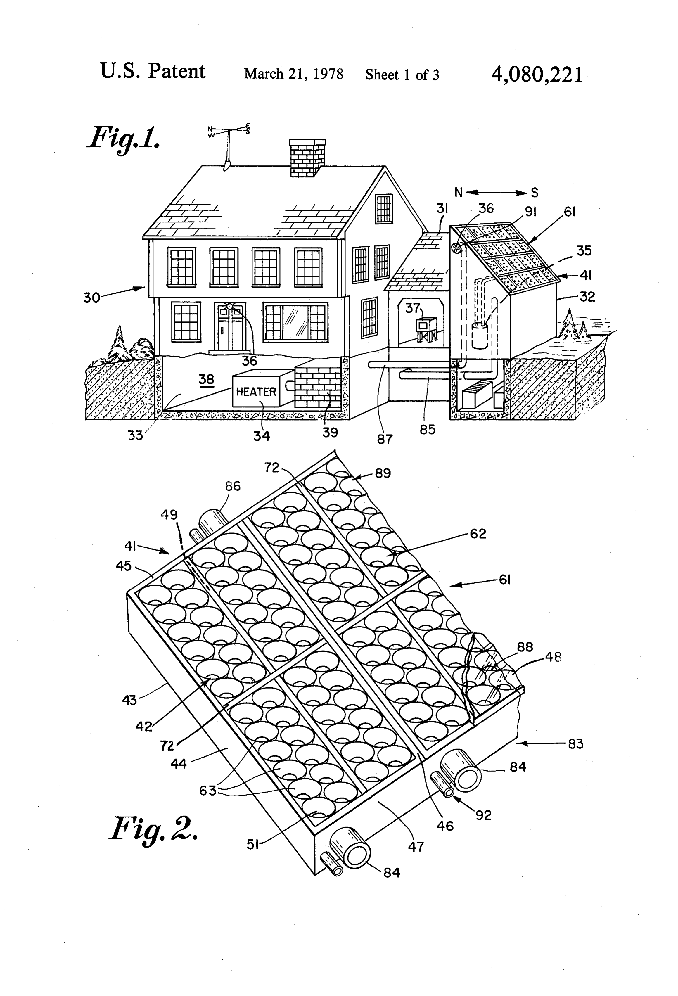
To increase the energy produced by an array of solar ofFIG. 1 is a schematic perspective view from the front a typical residence showing the solar system of the cells, it has been proposed in U.S. Pat. No. 3,108,313 to
Gattone of Jan. 23, 1962 to provide a plurality of super 20 invention
FIG. 2 installed therein; and with parts broken away;
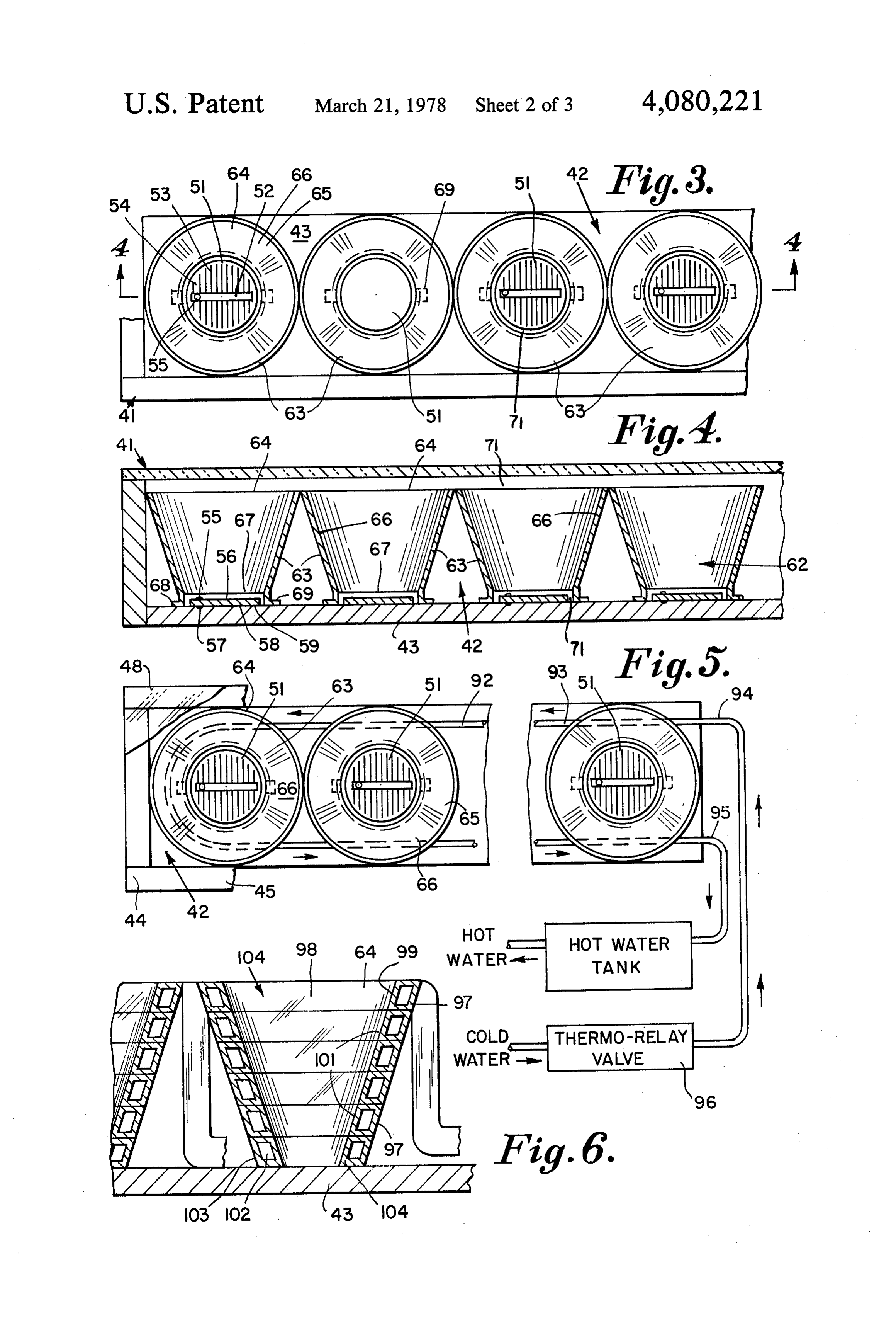
is an enlarged, fragmentary, perspective view posed layers of light convergent lenses arranged in of a power pack unit of the invention; cascade for intensifying the light received by the cells. FIG. 3 is a still further enlarged fragmentary top plan However, such lenses even when of plastic are costly view of a row of solar cells and truncated conical shells and the plastic used may not stand up in the heat gener of the invention;
ated within the enclosure by the sun, which may reach 25 FIG. 4 is a front elevation in section on line 4-4 of 200 Fahrenheit or over. FIG. 3;
SUMMARY OF THE INVENTION FIG. 5 is a view similar to FIG. 3 showing a fluid conduit in the enclosure;
In this invention the solar cells are mounted at spaced FIG. 6 is a side elevation, in half section, of a trun distances apart on a rigid planar backing, or bottom, of 30 cated an enclosure, the backing being black and each cell squareconical shell formed by a convoluted pipe of cross section to form a liquid jacket therearound;
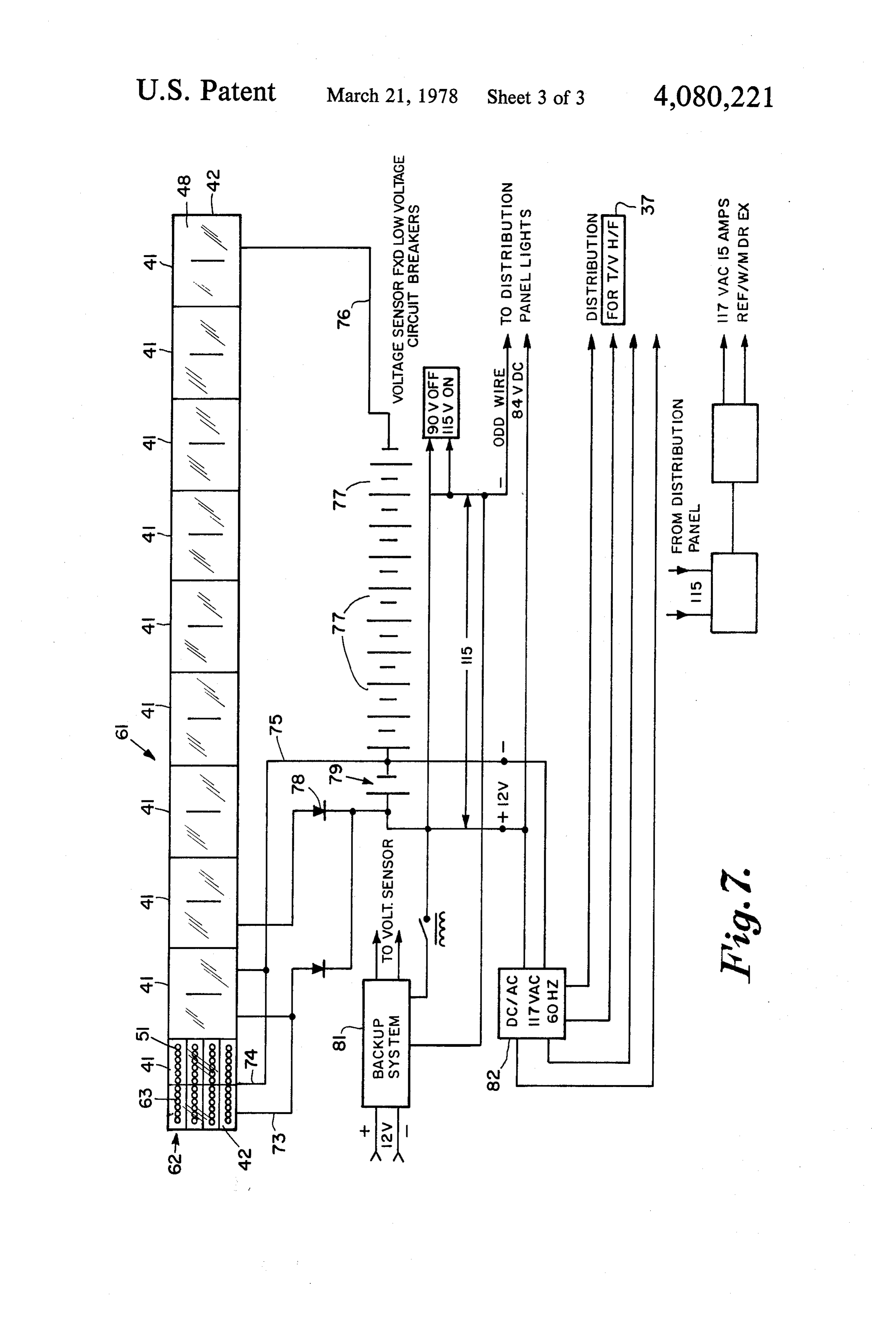
being a disc of predetermined area. Such discs are com and mercially available for example from Solar Power Cor FIG. 7 is a circuit diagram of a typical installation of poration, 5 Executive Park Drive, Billerica, Massa the system of the invention.
chusetts. They are about 3.5 inches in diameter, capable 35 of producing about 0.6 watts of energy in strong sun DESCRIPTION OF A PREFERRED light and costs about $15.00 each. Used alone, an array EMBODIMENT of such discs would cost about $45,000.00 to produce As shown in FIG. 1 a typical building such as the 300 kilowatts of energy a month. residence 30, may have a breezeway 31, an ell 32, cellar Instead of costly "plexiglass' lenses, in this invention 33, hot air heating system 34, main tap water heating I provide an array of truncated-conical, light-collector system 35, electric appliances 36 and a television37. In shells, preferably of aluminum with a mirror-like high the ambient air space 38 of the cellar 33 there is a heat polish finish, inner surface on the truncated conical side storage member 39 which may be constructed of about wall of the shell. Thus, the solar cells may be of small five tons of apertured fire bricks and which is arranged diameter and spaced apart for reduced cost, but the 45 store solar heat for use when needed on sunless days. sunlight is collected in the larger opening of the shell to The power pack panel 61 of the invention is about 8 and reflected from the polished surface down through feet wide, 16 feet long and 12 inches thick and is prefer the smaller opening of the shell to the cell it encircles. ably mounted at an angle of 45 from the horizontal The solar cells are electrically linked into a control facing South for example on the roof of the ell 32. The circuit which includes at least nine storage batteries, a 50 angle of inclination will depend on the geographical one way diode to prevent energy returning to the cells location, 45" having been found best for the Common when darkness occurs and the household electric circuit wealth of Massachusetts.
with its appliances. Because a television set requires The power pack unit 41, includes a substantially alternating current, the circuit preferably includes a sealed, separate large storage battery for powering the televi 55 bottomweather tight enclosure 42 having a rigid, planar which is preferably black, side walls 44, 45, sion and energized by the solar cells, there being a suit 46 and 47, upstanding from bottom 43 and preferably of able DC/AC converter in the circuit. rectangular configuration, and a top, or cover, 48 of The enclosure containing the array of cells and trun transparent material such as plastic of the "Plexiglass', cated conical light collectors is sealed and weather or glass, type. The bottom 43 and the side walls 44, 45, proofed to protect the parts from the elements. The 46 and 47 are of heat insulation sheet material, or in enclosure includes a cold air inlet in the lower portion clude a central layer 49 of heat insulation such as supplied from the ambient air in a building to be heated, "Fiberglas' to prevent losing heat to the ambient atmo and includes a hot air outlet in the upper portion of the sphere.
enclosure which connects to a fire brick heat storage Within the sealed enclosure 42 a plurality of light-sen member in the cellar of the building and thence to the 65 sitive, voltage producing, solar cells 51 are arrayed in a hot air heating system of the building. The metal shells common plane, at predetermined spaced distances of the invention are of heat conductive metal and act as apart, on the rigid planar bottom 43. The cells 51 may heat absorbers and radiators in heating the air in the be of any suitable type, but preferably are silicon cells of 6 flat, thin disc, or wafer, configuration, commercially 82 to the television 37 which requires alternating cur available, for example, from Solar Power Corporation, rent. Batteries 77 are preferably of the lead acid type 5 Executive Park Drive, Billerica, Massachusetts. Each such as an Eastern 375 amp hour battery having a stor solar cell 51 is of predetermined area with a diameter of age capacity of 4500 watts. Nine such batteries in series about three and one half inches and includes an electri 5 produce 110 volts DC at 47 amperes for 8 hours and can cally conductive back bone 52, with spaced rods, or supply the building 30 for 7 days of energy with 25% wires 53, normal thereto and in parallelism with each generated from the solar panels 61. Such batteries cost other, all embedded in a black backing 54 with one in total $847, and weight about 2000 pounds. terminal 55 on the backbone 52 on the exposed face 56 Backup unit 81 is an electric starting gasoline engine (FIG. 4) of the silicon cell and the other terminal 57 on 10 motor generator, which is automatically connected into the foil 58 on the underface 59 of the cell. Each cell is the system by the sensing of dull days, rain, etc. Low capable of producing 0.6 watts of energy in strong sun voltage circuit breakers, voltage regulators and DC to light. AC invertors, are provided to prevent over-discharge To permit the use of fewer costly solar cells, and of the batteries, provide a signal to the circuit breakers thereby bring the cost of the solar energy system 61 of 15 to open when the energy stored is at its minimum (100 the invention down to a reasonable amount, flared light volts) and to close when the batteries are at 110 volts. reflector means 62 is provided in each enclosure 42, The DC to AC invertor 82 is a 1200 watt square wave, preferably one for each cell 51 therein. The flared light 60 cycle generator and it is powered with 12 volts DC reflector means 62 is mounted within the enclosure 42 between the array of spaced apart, common-planar cells 20 and DC turned on by a command from the small appliances.
to AC Invert Synchronous Convert is a generator 51 and the transparent top 48 for collecting light from powered the sun over a larger total area than the total area of the appliances,fromthis 110 volt batteries to operate the heavy device consists of a 1.2 horsepower, 110 cells in the enclosure and reflecting the light onto the volt DC motor permanent magnet type driving direct a cells as the sun rises and sets during the day.
3000 watt alternator at a speed of 2500 rpm. A trans
Flared light reflector means 62 preferably comprises 25 ducer a plurality of truncated conical shells 63 of aluminum, relay supplies the power for on and off as com or other heat conductive material. Each shell has a large manded by the appliances.
open end 64 proximate the top 48, and of substantially Air heating means 83 includes the sealed enclosures greater area than the area of a cell 51, a truncated-coni 42, the heat conductive aluminum shells 63, a cold air cal side wall 65 with a mirror-like polished, light-reflec 30 inlet 84, connected by air ducts 85 to the space 38 in the tive, inner, flared surface 66 and a small open end 67, cellar 33, or elsewhere in residence 30, and a hot air encircling a cell 51 at a spaced distance thereabove by outlet 86 connected by hot air duct 87 to the heat stor support of a pair of integral legs 68, 69 affixed to the age member 39 and thence to the house air heating planar bottom 43. system 34. The air within the enclosures 42 rises to 200 In the illustrated embodiment wherein the cells 51 are 35 Fahrenheit or more due to the heat radiation of the sun each about 3 inches in diameter, the small open end 67 blackand the inner walls of the enclosure and the bottom are is about 3 inches in diameter and supported about to absorb heat. The shells 63 serve as heat absorb inch above the cell to provide air circulation space 71. ers and heat radiators to heat the cold air entering in the The large open end 64 is about 7 in diameter and the lower portions 88 of the enclosures and exiting from the side wall 65 is about 4 inches in vertical height. upper portions 89 as hot air. The heat storage member Preferably the truncated conical side wall 65 of each 39 preferably comprises a maze of apertured fire brick, shell 63 is inclined at about 15° from the vertical, of 75' but it could be any well known type of rock storage from the plane of enclosure bottom 43, since this degree device. A suction fan 91, powered by the batteries 77, is of inclination in the Massachusetts area provides the provided in hot air duct 87.
optimum angle for collecting useful sunlight in the open 45 A supplementary tap water system 92 (FIG. 5) is also ends 64 and reflecting the light out through the small provided, consisting of a liquid conduit 93, such as a ends 67 onto the cells 51. glass, copper or high temperature plastic tube, extend Each power pack unit 41, of the invention preferably ing alongside the peripheries of the cells 51, proximate comprises 48 solar cells 51 with 48 shells 63 enclosed in the plane thereof, to heat the water therein. The tubes a weatherproof enclosure 42, about 40 inches wide by 50 93 extend within the enclosure 42, from a liquid inlet 94 96 inches long and 73 inches deep, there being cruci to a liquid outlet 95, the tubes being connected to the form dividers 72 to form groups of twelve. The 48 cells hot water storage tank of the main tap water heating of each unit are connected in series to conductors 73 system 35, to supplement the hot tap water therein and 74 (FIG. 7). The approximate cost of each unit 41 is under the control of a thermo-relay valve 96. $600.00 and it produces 150 watts of electrical power, 55 As shown in FIG. 6the truncated conical shells of the each cell 51 producing 3.5 watts because of the truncat invention can be formed by a plurality of coiled convo ed-conical shells 63 rather than 48 x 0.6 or 28.8 watts lutions 97 of an elongated tube 98, of square, triangular without the shells, an increase by a factor of six. or rectangular cross section so that a mirror like finish The solar system 61 includes about ten power pack 99 is carried on the inner flared side wall 101 while a units 41, which may be arranged in a string, or row, or fluid 102 such as air or water is heated by the heat of the in multiple in a frame, the units 41 being electrically sun. The small end 103 of the flared coiled tube shell 104 connected in series by conductors 75 and 76 into a is affixed to the bottom 43 with no integral legs. power circuit including about nine storage batteries 77, While I prefer that the flared, light-collecting, reflec and a one way diode 78, to energize the batteries from tive, shells of the invention be full truncated cones and the light of the sun. The household appliances 36 are 65 that there be one shell for each solar disc, it has been powered by batteries 77, or by a back up unit 81, if five found that a three quarter, or 270 shell will produce or six successive sunless days occur. A separate large good results. Also, it is possible that one large shell can battery 79, is connected through a DC/AC converter be provided for a plurality of spaced solar discs but one 7 shell for each cell is preferable for increasing both de itous path alongside the outer peripheries of said velopment of electric energy as well as heat. cells and thence back outside said enclosure; It has been found that for example, a cluster offive of whereby said conduit picks up heat in said enclosure, the solar cells 51 closely packed in tangential contact all and from said shells, to deliver heated water from in a flat plane, in combination with a single enlarged 5 said enclosure while said cells generate electricity. light collecting shell 63, having a small opening of the 6. A power pack unit as specified in claim 1 wherein: same general area as that of the cluster but an enlarged said truncated conical reflectors are each formed of a opening at the light receiving end, instead of producing plurality of convolutions of hollow tubing, said 5 X 0.6 or 3 watts without the shell, increases almost tubing being interconnected throughout said enclo three times (to 5 X 1.7 watts) to provide 8.5 watts. In 10 sure and having an inlet end and an outlet end other tests, a semi-circular flared shell produced 0.9 outside said enclosure;
watts, as compared to the normal 0.6 watts. A 270 whereby the inner mirror-like surface of said convo flared shell produced 1.16 watts and a 360' flared shell luted tube reflectors reflects light to said solar cells produced 1.6 watts. A cylindrical shell, developed so while fluid within said tubing becomes heated by much shadow that its effect was negligible in increasing 15 solar radiation.
Wattage. 7. A power pack unit for converting solar energy into I claim: electric energy, said pack comprising: 1. A power pack unit for converting solar energy into a plurality of electrically-linked, light sensitive, volt electric energy, said pack comprising: age producing solar cells arranged in spaced array a substantially sealed, weather tight enclosure having 20 on a rigid backing;
a planar bottom of rigid material, upstanding side a plurality of open-ended, truncated-conical light-col walls and a top of transparent material; lector shells of heat conductive sheet metal, each a plurality of light sensitive, voltage producing solar with its large end adapted to face the sun, the inner cells arranged in spaced array on said bottom, each surface of its truncated conical side wall having a cell being of predetermined area; 25 light reflective surface and its small end supported a plurality of truncated conical reflectors arranged in on legs at a spaced distance above said backing, to spaced array in said enclosure, between said cells encircle a said cell;
and said top for collecting sunlight and heat from a and weathertight enclosure means on said backing, larger total area than the total area of said cells and enclosing said cells and shells, said means including reflecting said light into said cells 30 a transparent top at a predetermined distance and means mounting each said truncated conical re above the large ends of said shells for admitting flector with its small end at a predetermined spaced sunlight thereinto, distance above said bottom and its large end at a whereby air may circulate around the large ends, side spaced distance below said top to permit circula walls and small ends of said shells. tion of air within and around said enclosure. 35 8. A power pack unit as specified in claim 7 wherein 2. A power pack unit as specified in claim 1 wherein: said enclosure means includes fluid inlet means and each said reflector is of heat conductive aluminum fluid outlet means for heating a fluid within said with its truncated conical side wall inclined at. enclosure.
about seventy five degrees from the plane of said 9. A system for converting solar energy into electric planar bottom of said enclosure and having an 40 energy while also producing heat, said system compris inner, mirror-like reflective surface. 1ng:
3. A power pack unit as specified in claim 1 wherein: a building having a plurality of electric appliances said means for mounting said reflectors comprises leg and a hot air heating system and; means supporting the small end thereof, and affixed a power pack unit, said unit including: to said planar bottom, to position said shell at said 45 a weathertight, insulated, enclosure associated with predetermined height thereabove for circulation of said building, said enclosure having a rigid planar air therearound. bottom, side walls upstanding therefrom and a 4. A power pack unit as specified in claim 1 wherein: transparent top;
said truncated conical reflectors are of heat conduc said enclosure being inclined at a selected angle to the tive material, each having a mirror-like inner sur- 50 horizontal with said transparent top facing gener face reflecting light received in the large end ally South;
thereof, into said solar cell mounted below the a plurality of electrically-linked, light-sensitive volt small end thereof and; age-producing solar cells spaced on said bottom, said enclosure includes a cold air inlet, a hot air outlet each of predetermined area; and a liquid conduit connecting a liquid inlet to a 55 a plurality of truncated-conical shells of heat conduc liquid outlet, tive material mounted within said enclosure, each whereby said enclosure and said shells are heated by having leg means supporting its small end at a the sun to deliver heated air from said air outlet and spaced distance above, and encircling one of said heated liquid from said liquid outlet while said cells cells, its inner side wall having a reflective surface generate electricity, 60 and its large end at a spaced distance below said 5. A power pack unit as specified in claim 1 wherein: transparent top and facing the sun said truncated conical reflectors are of heat conduc electric circuit means including said cells, a one way tive material, each having a mirror-like inner sur diode, a weries of storage batteries and said appli face reflecting light received in the large end ances; further including thereof into one of said solar cells at the small end 65 liquid circulation means within said enclosure; thereof; and air heating means including a cold air inlet to said said enclosure includes a cold water supply conduit, enclosure connected to the space within said build extending from outside said enclosure in a circu ing, heat conductive material forming said shells, 8 and a hot air outlet from said enclosure connected to the hot air heating system of said building, said means including a heat storage member of fire brick interposed between said enclosure and said 5 hot air heating system.
10. A system as specified in claim 9 wherein: said building includes a main tap water heating sys said liquid circulation means comprises a water con duit extending into said enclosure from the hot water tank of said main system, said conduit tra versing said enclosure and then connecting back to 15 said tank, there being a thermal relay valve in said liquid circulation means for controlling the same. 11. A power pack unit for converting solar energy into electric energy, said pack comprising: a substantially sealed, weather tight enclosure having 20 a planar bottom of rigid material, upstanding side walls and a top of transparent material;
a plurality of light sensitive, voltage producing solar cells arranged in spaced array on said bottom, each cell being of predetermined area;
a plurality of truncated conical reflectors arranged in spaced array in said enclosure, between said cells and said top for collecting sunlight and heat from a larger total area than the total area of said cells and reflecting light into said cells, each said shell being of heat conductive material, having a mirror-like inner surface reflecting light, received in the large end thereof, through the open small end thereof into a cell mounted below said small end thereof;
means mounting each said truncated conical reflector with its said small end at a predetermined spaced distance above said bottom to permit circulation of air within and around said enclosure;
and said enclosure having a cold air inlet and a hot air outlet.
whereby said cells generate electricity while said reflectors absorb heat from the sun to heat air within said enclosure.
Provenance
- Collection
- Patents citing this work
- Pages
- 8
- Method
- pdftotext (the PDF's own text layer) + pdftoppm 300dpi page scans
- Patent office record
- patents.google.com →
- Source
- Google Patents citing-documents table
- Assignee
- Manelas Arthur J
- Published
- 1978-03-21
- Transcribed from
- patentimages.storage.googleapis.com →