

patent · US4087045A
Stack damper control safety interlock with lockout prevention
2 May 1978
Text
Page 1scan →
United States Patent (19)
Matthews
54). stack damper control safety
Interlockwth lockout
Prevention
75 Inventor: Russell Byron Matthews, Goshen, Ind.
73 Assignee: Johnson Controls, Inc., Milwaukee, Wis.
52 u.s. c. ................................... 236/1 g; 110/163;
58) Field of Search ....................... 236/1 G; 110/163;
2,155,642 4/1939 Dewey 236/1 G
3,986,813 10/1976 Hewitt ................................... 431/46
Foreign patent documents
737,709 7/1966 Canada ................................ 236/1 G
Senseng
MAN by NER 's IT OUTLE
To fuel
Primary Examiner-William E. Wayner
Assistant Examiner-R. J. Charvat
Attorney, Agent, or Firm-Emrich, Root, O'Keeffe & Lee
A control arrangement for a heating system including a furnace having a fuel-fired burner apparatus and a vent stack with a motor driven damper plate for opening and closing the stack, includes an interlock switch which provides a safety interlock between fuel supply valves of the system and first and second limit switches which control the energization of a drive motor for the damper plate and effect energization of the fuel supply valves of the system, permitting the fuel valves to oper ate only when the damper plate is in the open position and preventing energization of the fuel valves in the event of a malfunction of either of the limit switches. The interlock switch also permits recycling of the sys tem in the event of a momentary power interruption. The control arrangement may include a stack mounted heat sensor switch which interrupts the energizing path for the fuel supply valves in the absence of heat from the main burner within a predetermined interval of time.
20 Claims, 2 Drawing Figures
Flame
Sensor
Drawings
Page 2drawing sheetscan →
Page 3drawing sheetscan →
Page 4scan →
which provides a safety interlock between the stack
STACKDAMPER CONTROLSAFETY INTERLOCK damper control apparatus and fuel supply apparatus of WTH LOCKOUT PREVENTION the system.
BACKGROUND OF THE INVENTION Another object of the invention is to provide a heat ing system including a motor actuated damper appara 1. Field of the Invention tus which is interlocked with the fuel valves of the This invention relates to heating systems including system to permit operation of the fuel valves only when furnaces having fuel-fired burners, and, more particu the damper is in a fully open position. larly, to a control arrangement which provides a safety Another object of the invention is to provide a con interlock between a stack damper control apparatus and 10 trol arrangement for a stack damper apparatus and fuel fuel supply apparatus for such systems. supply apparatus of a heating system, which prevents 2. Description of the Prior Art lock out of the system following a momentary power Heating systems employing furnaces having fuel interruption.
fired burners require a vent stack to conduct combus Yet another object of the invention is to provide a tion products away from the burner. Automatically 15 control arrangement for a heating system including controlled stack dampers are generally used in the ven stack damper control apparatus, which prevents the tilation stacks to permit the stacks to be closed when the operation of fuel supply valves of the system in the furnace is not operating to minimize heat losses when event of an unsafe failure of the stack damper control the furnace is not operating. However, for safe opera apparatus.
tion, it is necessary that the stack damper be open in 20 These and other objects are achieved by the present advance of each operation of the burner. Accordingly, invention which has provided a control arrangement systems in which automatic dampers are used generally for use in a heating system and which provides a safety include a control arrangement which provides an inter interlock between a fuel supply means which supplies lock between the damper control mechanism and fuel fuel to a burner apparatus of the system for combustion supply apparatus of the system to assure that the 25 to provide heat, and a stack damper control means damper is fully open before the burner operates and is which controls the positioning of a stack damper plate closed after the completion of the operation of the which is pivotally mounted within a vent stack. The burner. damper plate is normally maintained in a first position to In one known arrangement in which a primary close the vent stack when the system is deactivated, and burner control is conditional on and subsequent to the 30 is rotatable to a second position to open the vent stack opening of a stack damper, a drive motor is energized in when the system is activated. The control arrangement response to a request for heat to drive the damper to an comprises switching means operable when energized to open position, and limit switches complete the burner prepare an energizing path for the fuel supply means, circuit and deenergize the drive motor when the first limit switch means for preparing an energizing path damper reaches the fully open position. The drive 35 for the switching means and drive motor whenever the motor is reenergized at the end of the heat run to move damper plate is at the first position, and activate means the damper to the closed position, a further switch de responsive to a request for heat to effect the energiza energizing the motor when the damper reaches the tion of the switching means and the drive motor over closed position. Movement of the damper from the fully the first limit switch means to permit the damper plate open position permits a limit switch to interrupt the to be driven towards the second position. The first limit burner circuit. A time lag is provided between the inter switch means is operable when the damper plate has ruption of the burner circuit and the closing of the been driven to the second position to deenergize the damper to allow volatiles to be purged from the furnace drive motor and to complete the energizing path for the following operation of the burner. fuel supply means. The activate means is operable when When operating properly, systems such as the type 45 the heating demand has been met to deenergize the fuel referred to above provide the desired interlock between supply means and the switching means, permitting the the stack damper and the fuel supply apparatus. How drive motor to be reenergized to drive the damper plate ever, under certain failure conditions, such as the weld to the first position. A second limit switch means is ing together of contacts of the limit switches, or, when operable when the damper plate has been driven to the cam-operated switches are used, the cams becoming 50 first position to effect the deenergization of the drive loose and shifting out of place, the fuel supply valves motor.
may be energized while the vent stack is closed. More The safety interlock between the fuel supply means over, due to the interlock arrangement, the system may and the stack damper control means is provided by the become locked out following a momentary power inter first and second limit switch means and the switching ruption, an undesirable condition. 55 means. In accordance with a disclosed embodiment, the Therefore, it would be desirable to have a control switching means is embodied as a switching device, arrangement for use in a heating system which provides such as a relay, and the first and second limit switch a safety interlock between a stack damper control appa means comprise cam operated switches which are cou ratus and fuel supply apparatus of the system which pled to a drive shaft of the motor. The interlock relay is prevents operation of the fuel supply apparatus when energized over the first and second limit switches at the ever the damper is in a position other than a fully open start of each heating cycle and operates to close associ position, or in the event of an unsafe failure of the con ated contacts which are connected in the energizing trol apparatus, and which prevents lock out of the sys path for the fuel supply means. The limit switches per tem following a momentary power interruption. mit the energization of the drive motor causing the 65 damper plate to be driven to the open position and also
Summary of the invention
interrupt the energizing path for the interlock relay,
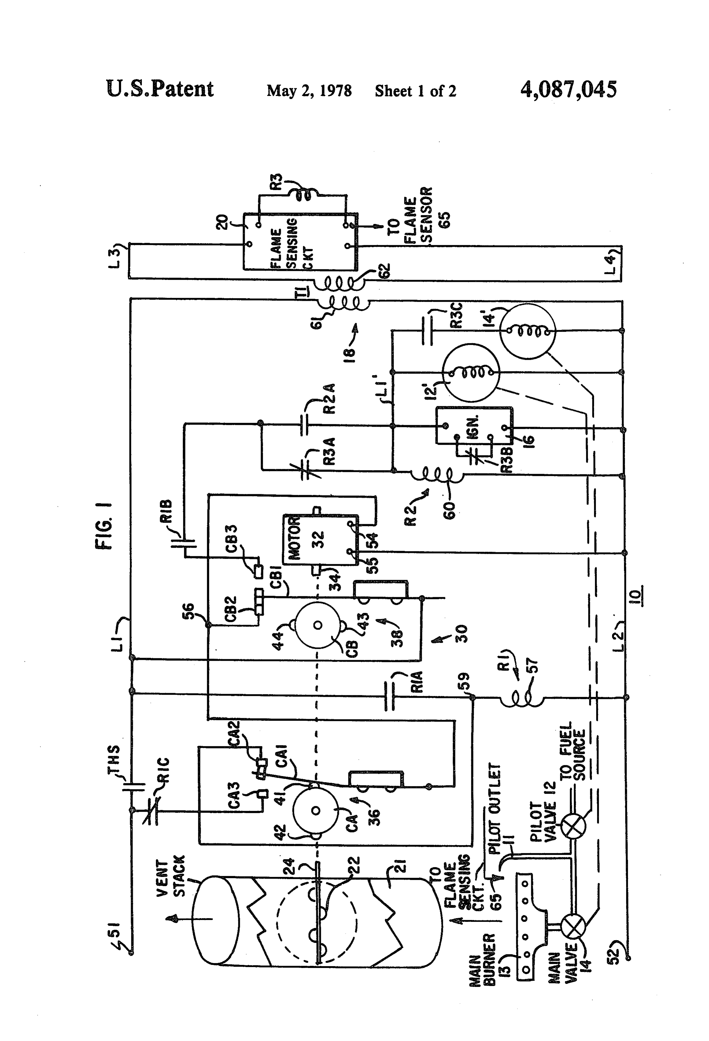
It is therefore an object of the present invention to which is maintained by a holding path provided by provide a control arrangement for a heating system further contacts of the relay. When the damper plate 5 has been driven to the fully open position, the first limit from the main burner apparatus. In the absence of heat switch operates to complete the energizing path for the from the main burner apparatus within a predetermined fuel supply means. In the event that the interlock relay time after the heating element is deenergized, the heat fails to operate at the start of a heating cycle, such as sensor switch operates to open the contacts thereby due to a malfunction of either limit switch or of the deenergizing the fuel supply means. interlock relay itself, the energizing path for the fuel The use of the heat sensor switch guards against supply means is maintained interrupted, even though unsafe conditions, such as a simultaneous failure where, the damper plate is at the open position and the first following a successful start-up, an unsafe failure occurs limit switch operates to complete a portion of the ener in the flame sensing circuit which is then followed by a gizing path. 10 flame-out, which would other wise permit fuel to be Thus, the control arrangement of the present inven supplied to the main burner apparatus without ignition. tion not only provides for the energization of the fuel DESCRIPTION OF THE DRAWINGS supply means only when the damper plate is at the fully open position, but also guards against unsafe failure of FIG. 1 is a schematic circuit diagram for a control one or both limit switches, preventing the energization 15 arrangement for a heating system provided in accor of the fuel supply means in the event of such occur dance with one embodiment of the invention; and, 16C. FIG. 2 is a schematic circuit diagram for a control In accordance with a feature of the invention, the arrangement for a heating system provided in accor interlock relay has further contacts connected in the dance with a second embodiment of the invention. return drive path for the drive motor, and is responsive 20 to the activate means to complete the return drive path DESCRIPTION OF PREFERRED when the heat demand has been met, permitting the EMBODIMENTS drive motor to be reenergized to drive the damper plate Referring to the drawings, FIG. 1 is a simplified to the first position. This feature also prevents the heat representation of a heating system 10 employing a con ing system from becoming locked out in the event of a 25 trol arrangement provided by the present invention. In power interruption during a heating cycle. the exemplary embodiment, the heating system 10 is of In the event of a power interruption during a heating the cycle, the interlock relay is deenergized, permitting the firedpilot ignition type. The system 10 includes a fuel drive motor to be reenergized when the power is re main burner 13,apparatus heating a pilot having a pilot outlet 11 and a valve 12, a main valve 14, and an stored, so that the damper plate is returned to the closed igniter circuit 16, the operation of which are controlled position. When the damper reaches the closed position, by a fuel ignition control circuit operation of the limit switches permits a new heating flame sensing circuit 20 and a relay18R2.which The includes a pilot valve cycle to be initiated. 12 is operable when energized to supply fuel to the pilot In an application in a pilot-ignition type heating sys outlet tem, including a pilot valve and a main valve, and an 35 circuit1116for to ignition by sparks provided by the igniter provide a pilot flame. The main valve 12 is electronic flame sensing means, an interlock may be operable under the control provided between the fuel supply means and the flame 20 to supply fuel to the mainofburner the flame sensing circuit 13 for ignition by sensing means to permit the interruption of the energiz the pilot flame to establish a flame at the main burner 13 ing path for the fuel valves in the event of a malfunction for providing heat for the system. of the flame sensing means which would otherwise permit fuel to be supplied to the main burner apparatus 21The heating system 10 further includes a vent stack for venting combustion products away from the in the absence of a flame. In accordance with a further feature of the invention, the flame sensing means is main burner 13 when the main burner is lit. A stack energized in response to the activate means in response damper plate 22 is pivotally mounted within the stack to a request for heat, so that in the event of a malfunc 45 by waypositions of a shaft 24 for movement between closed and tion in the flame sensing means, the time that is required open under the control of a stack damper control circuit 30, including a drive motor 32. The shaft for the drive motor to drive the damper plate to the 24 is mechanically linked to a drive shaft 34 of the drive fully open position affords sufficient delay for the flame sensing means to interrupt the energizing path before motor 32 which is operable when energized to drive the the limit switch operates to apply power to the energiz 50 damper plate 22 between the closed and open positions. ing path for the fuel valves. The damper plate 22 is normally maintained in the In accordance with another feature of the invention, closed position, as illustrated in FIG. 1, when the sys the system may also include a heat sensor switch means tem 10 is deactivated, so that the vent stack 21 is closed, which is responsive to the activate means to permit the preventing heat loss via the vent stack 21. In response to energization of the fuel supply means over the energiz 55 a request for heat, the stack damper control circuit 30 ing path, the heat sensor switch means being operable in energizes the motor 32 to permit the damper plate 22 to the absence of heat from the main burner apparatus be driven from the closed position to the open position, within a predetermined time following the energization represented by the dotted line in FIG. 1 to permit com of the fuel supply means to interrupt the energizing bustion products to be vented away from the main path. In accordance with a disclosed embodiment, the burner. The stack damper control circuit 30 includes a heat sensor switch means includes normally open first limit switch 38 which effects the deenergization of switch contacts which are connected in the energizing the motor 32 when the damper plate 22 reaches the path for the fuel supply means, and a heater element open position. When the heating demand has been met, which is energized over one of the limit switch means the stack damper control circuit 30 reenergizes the responsive to the activate means to cause the contacts to 65 drive motor 32 to permit the damper plate 22 to be close. The heater element is deenergized when the limit driven to the closed position. A second limit switch 36 switch means is operated whereby the heat sensor effects deemergization of the motor 32 when the damper switch maintains the contacts closed responsive to heat plate 22 reaches the closed position.
Page 6scan →
The limit switches 36 and 38 each comprise cam the energization of the main valve 14through the opera actuated switches, the operation of which is controlled tion of an associated relay R3, permitting fuel to be by way of cams CA and CB. The cams CA and CB are supplied to the main burner apparatus for ignition by mechanically linked to the shaft 34 of the motor 32. The the pilot flame.
limit switch 36 includes a resilient switch arm CA1, The fuel ignition control circuit 18 includes an inter which is movable by way of cam CA, and a pair offixed lock relay R2 which prevents operation of the fuel contacts CA2 and CA3. Cam actuator portions 41 and valves 12 and 14 in the event of a malfunction in the 42 are disposed at diametrically opposed positions along flame sensing circuit 20 which would otherwise permit the periphery of the cam CA. As shown in FIG. 1, operation of the main valve 14 in the absence of a pilot actuator portion 41 maintains switch arm CA1, which is 10 flame. The fuel ignition control circuit 18 is initially biased to normally engage contact CA3, in engagement energized over normally closed contacts R3A of relay with contact CA2 when the damper plate 22 is in the R3, to permit operation of the pilot valve 12 and the closed position. When the cam CA is rotated approxi energization of relay R2. When relay R2 operates, a mately 5, the actuator portion 41 disengages the switch holding path is provided over contacts R2A of the relay arm CA1 which then moves out of engagement with 15 R2. The fuel ignition control circuit 18 is maintained contact CA2 and into engagement with contact CA3. energized over the holding path provided by contacts When the cam CA has been rotated through 180", actu R2A of relay R2 when relay R3 operates to open ator portion 42 engages the switch arm CA1, moving contacts R3A when a pilot flame is established. Failure the switch arm CA1 out of engagement with contact of a relay R2 to operate prior to operation of relay R3 CA3 and into engagement with contact CA2. 20 permits the deenergization of the fuel ignition control Similarly, limit switch 38 includes a resilient switch circuit 18. Also, relay R2 is prevented from operating, arm CB1, which is movable by cam CB, and fixed preventing operation of the main valve 14 whenever contacts CB2 and CB3. Cam CB has cam actuator por contacts R3A are open at the time limit switch 38 oper tions 43 and 44, which are normally disengaged from ates to apply power to the fuel ignition control circuit the switch arm C1B permitting the switch arm CB1 to 25 18.
engage contact CB2 when the damper plate 22 is in the When the heating demand has been met following a closed position. The cam actuator portion 43, for exam successful heating cycle, the thermostatically con ple, causes the switch arm CB1 to be moved out of trolled contacts THS open, causing relay R2 and the engagement with contact CB2 and into engagement fuel valves 12 and 14 to be deenergized. In addition, with contact CB3 with 90' of rotation of the cam CB to 30 relay R1 also drops out, closing contacts R1C which a position corresponding to the fully open position for complete an energizing path for the motor 32 over limit the damper plate 22. - switch 36, permitting the damper plate 22 to be driven Contacts CB1 and CB2 of limit switch 38 provide an to the closed position. Limit switch 36 operates to deen energizing path for the drive motor 32 when contacts ergize the motor 32 when the damper plate reaches the THS close in response to a request for heat, and deener- 35 closed position.
gize the motor 32 when the damper plate 22 reaches the The motor 32 operates at a specific speed and pro fully open position. Contacts CB1 and CB2 of limit vides sufficient time for the interlock circuit to operate switch 38, along with contacts CA1 and CA2 of limit at the start of a heating cycle. The timed closing of the switch 36, provide an energizing path for an interlock damper plate 22 at the end of each heating cycle allows relay R1. Contacts CB1 and CB3 of limit switch 38 40 combustion products to be vented from the vent stack provide an energizing path for the fuel ignition control 21 before the damper plate 22 is returned to the closed circuit 18, and contacts CA1 and CA3 of limit switch 36 position.
provide a return drive energizing path for the motor 32 The position of the damper plate 22 is mechanically and deenergize the motor 32 when the damper plate 22 interlocked with limit switch 38, allowing actuation of reaches the closed position. 45 the limit switch 38 only when the damper plate 22 is In accordance with the present invention, the stack fully open. This provides a safety aspect such that it is damper control circuit 30 is interlocked with the fuel impossible to manually operate the damper plate 22 to ignition control circuit 18 by way of the limit switches any position other than fully open and simultaneously 36 and 38 and the interlock relay R1 which permit cause the fuel valves 12 and 14 to be electrically actu energization of the fuel ignition control circuit 18 only 50 ated. The limit switches 36 and 38 are electrically inter when the damper plate 22 is in the fully open position. connected so that the energization of relay R1 is pre The interlock relay R1 is energized over the limit vented in the event of a malfunction of either switch, switches 36 and 38 following the operation of thermo thereby maintaining the fuel ignition control circuit 18 statically controlled contacts THS in response to a re deenergized. Also, the interlock afforded by relay R1 quest for heat. Relay R1 is operable when energized to 55 and limit switches 36 and 38 prevents the system 10 close associated contacts R1A which provide a holding from being locked out following a power interruption path for the relay R1. Also, contacts R1B of relay Ril during a heating cycle.
are closed preparing an energizing path for the fuel Moreover, the proper operating sequence of the re ignition control circuit 18. When the damper plate 22 lays R1-R3 and the limit switches 36 and 38 must be has been rotated to the fully open position, limit switch 60 maintained in order to effect the energization of the fuel 38 operates whereby an energizing path is completed ignition control circuit 18, permitting the fuel valves 12 over limit switch 38, permitting power to be applied to and 14 to operate as will be shown hereinafter. the fuel ignition control circuit 18. Limit switch 38 also Considering the heating system 10 in more detail, deenergizes the motor 32. power is supplied to the system 10 over input terminals When power is applied to the fuel ignition control 65 51 and 52 thereof which are connectable to a 25 VAC circuit 18, the pilot valve 12 and the igniter circuit 16 source. Terminal 51 is connected over normally open are energized to establish a pilot flame. When a pilot thermostatically controlled contacts THS to a conduc flame is established, the flame sensing circuit 20 effects tor L1, and terminal 52 is connected directly to a further 7 conductor L2. When the damper plate 22 is in the which was issued on September 2, 1975. As disclosed in closed position, the motor 32 is connected between detail in such patent, the flame sensing circuit 20 in conductors L1 and L2 over limit switch 38 which has its cludes a flame sensor 65 which is disposed in proximity movable arm CB1 connected to conductor L1 and its to the pilot outlet and is responsive to a pilot flame to fixed contact CB2 connected to one terminal 54 of the 5 effect the operation of relay R3 of the flame sensing motor 32, which has a second terminal 55 connected to circuit 20. The relay R3 operates to open contact R3A conductor L2, permitting the motor 32 to be energized to interrupt the energizing path to conductor L1' for the when contacts THS close. pilot valve solenoid and the igniter 14, which are then Contact CB2 of limit switch 38 is also connected at maintained energized over the holding path provided point 56 to the movable switch arm CA1 of limit switch 10 by contacts R2A of relay R2. Relay R3 also opens 36. Contact CA2 of switch 36 is connected to one side contacts R3B to disable the igniter 16 and closes of the operate coil 57 of relay R1 at point 59, the other contacts R3C to complete the energizing path for the side of which is connected to conductor L2. Accord main valve solenoid 14 between conductor L1 and L2. ingly, the operate coil 57 of relay R1 is also connected Relay R3 is a double-pole, double throw relay, with between conductors L1 and L2 for energization when 15 contacts R3A and R3C employing a common armature. ever contacts THS close. Thus, if contacts R3C become welded together, Relay R1 has normally contacts R1A connected be contacts R3A cannot reclose when relay R3 is deener tween point 59 and conductor L1 to provide a holding gized.
path for relay R1, and normally closed contacts RC OPERATION connected between input terminal 51 and fixed contact 20
CA3 of limit switch 36 for providing a return drive For the purpose of illustrating the operation of the energizing path for the motor 32 at the end of each control arrangement for the heating system 10, it is heating cycle. Relay R1 has further normally open assumed initially that the system 10 is deactivated with contacts R1B connected in series with normally closed the damper plate 22 in the fully closed position, and that contacts R3A of relay R3 between fixed contact CB3 of 25 the limit switches 36 and 38 are operated to the posi limit switch 38 and a conductor L1, to supply power to tions shown in FIG. 1. In response to a request for heat, the fuel ignition control circuit 18 when the limit switch contacts THS close, extending power to conductor L1 38 is operated to move its switch arm CB1 into engage for energizing the drive motor 32 over contacts CB1 ment with contact CB3. Relay R1 is a 3-pole, double and CB2 of switch 38, and for energizing relay R1 over throw relay, with contacts R1B and R1C employing a 30 contacts CB1 and CB2 of switch 38, and contacts CA1 common armature of the relay R1. Thus, should and CA2 of switch 36. The flame sensing circuit 20 is contacts R1B become welded together, contacts R1C also energized over transformer T1.
cannot reclose. When relay R1 operates, contacts R1A are closed Referring to the fuel ignition control circuit 18, the providing a holding path for the relay R1 between con operate solenoid 12" of the pilot valve 12, igniter 16 and 35 ductors L1 and L2, and contacts R1C are opened, inter the operate coil 60 of relay R2 are connected in parallel rupting the return drive energizing path for the motor between conductors L1' and L2". The operate solenoid 32. Also, contacts R1B of relay R1 are closed, preparing 14 of the main valve 14 is connected between conduc an energizing path for the pilot valve solenoid 12' and tors L1 and L2 over normally open contacts R3C of the igniter 16 which extends from fixed contact CB3 relay R3. Relay R2 has normally open contacts R2A, 40 over contacts R3A to conductor L1'. At this time, the connected in shunt with contacts R3A to provide a energizing path is interrupted by limit switch 38 since holding path for the pilot valve solenoid 12" and the switch arm CB1 is still engaging contact CB2. main valve solenoid 14 when relay R3 operates. When the motor 32 is energized, the motor shaft 34 The igniter circuit 16, may, for example, be the type rotates, moving the damper plate 22 toward the open disclosed in the U.S. Patent Application, Ser. No. 45 position. Cams CA and CB are also driven, and when 698,161, of G. E. Dietz, which is entitled, "Fuel Ignition cam CA has been rotated approximately 5, CA1 is System Including An Igniter Which Provides A Lin moved out of engagement with contact CA2, and into gering Spark.” The operation of the igniter is disclosed engagement with contact CA3 to prepare a return drive in detail in the referenced patent application. Briefly, energizing path for the motor 32, and to interrupt the when power is applied to the fuel ignition control cir 50 energizing path for relay R1 which is maintained ener cuit 18, the igniter circuit 16 is energized to provide gized over its contacts R1A.
ignition sparks for igniting fuel supplied to the pilot When the damper plate 22 has been moved to the outlet. When a pilot flame is established, the relay R3 fully open position, cam CB has been rotated approxi operates, opening contacts R3B, which are connected mately 90', permitting contact CB1 to move out of in an enabling circuit for the igniter circuit, to thereby 55 engagement with contact CB2, deenergizing the motor disable the igniter circuit 16. The igniter circuit 16 con 32, and engaging contact CB3, completing the energiz tinues to provide sparks for a predetermined time fol ing path for the pilot valve solenoid 12' and the igniter lowing the operation of the relay R3, assuring ignition 16 from conductor L1 over contacts CB1 and CB3 of of the fuel in the event of a malfunction in the flame limit switch 38, contacts R1A of relay R1 and contacts sensing circuit 20 which allows relay R3 to operate in R3A of relay R3 to conductor L1'. When the pilot the absence of a flame. valve 12 operates, fuel is supplied to the pilot outlet 11 The flame sensing circuit 20 is energized over a trans for ignition by sparks provided by the igniter 16. Relay former T1, which has a primary winding 61 connected R2 is also energized when power is applied to conduc between conductors L1 and L2, and a secondary wind tor L1', and operates to close contacts R2A to provide ing 62 connected between conductors L3 and LA which 65 a holding path in shunt with contacts R3A. are connected to input terminals of the flame sensing When a pilot flame is established, the flame sensing circuit 20. The flame sensing circuit 20 may be the type circuit 20, senses the pilot flame and effects energization disclosed in U.S. Pat. 3,902,839 of Russell B. Matthews, of relay R3. When relay R3 operates, contacts R3A are 8 opened, interrupting the energizing path for the pilot gizing path for the relay R2 and the pilot valve 12 is valve solenoid 12 and the igniter 16 which are main interrupted, preventing operation of the pilot valve 12 tained energized over the holding path provided by and the system 10 is maintained in a lock out condition. contacts R2A of relay R2. In addition, contacts R3B of In the event of a failure condition following a suc relay R3 are opened, disabling the igniter 16, and 5 cessful start up, such as the welding together of the contacts R3C are closed, energizing the main valve contacts R3C which control the operation of the main solenoid 14, supplying fuel to the main burner 13 for valve 14, then when the heating demand has been met, ignition by the pilot flame to provide heat to satisfy the and contacts THS open, the pilot valve 12 and the main heating demand for the system 10. valve 14 are deenergized, extinguishing the flame. The When the heating demand has been met, contacts 10 flame sensing circuit 20 responds to the loss of flame to THS open, interrupting the supply of power to conduc deenergize relay R3. However, since contacts R3C are tor L1, causing the deenergization of the fuel valves 12 welded together, contacts R3A cannot reclose since and 14, permitting the main burner flame and the pilot such contacts employ a common armature of the relay flame to be extinguished. The flame sensing circuit 20, R3. Accordingly, when contacts THS close on the next and relay R2 and relay R1 are also deenergized, and 15 call for heat, the energizing path for the fuel ignition when relay R1 drops out, contacts R1C close complet control circuit 18 is interrupted since contacts R3A are ing the return drive energizing path for the motor 32 open. Thus, the pilot valve 12 and the main valve 14 are over contacts CA1 and CA3 of limit switch 36 for ener maintained deenergized.
gizing the motor 32 to dirve the damper plate 22 to the The stack damper control circuit 30 also provides fail fully closed position. As the motor shaft 34 is driven, 20 safe operation for the stack damper 22 and the fuel cams CA and CB are rotated. When cam CB has been ignition control circuit 18. For example, in the event rotated approximately 5, switch arm CB1 is moved out CB1 of limit switch 38 becomes welded to fixed contact of engagement with contact CB3, interrupting the ener CB2, then, following activation of the system 10 gizing path for the fuel ignition control circuit 18, and through operation of contacts THS, the motor 32 con into engagement with contact CB2. When the damper 25 tinues to run, periodically moving the damper plate 22 plate 22 reaches the closed position, cam CA has been between open and closed position. However, the pilot rotated approximately 90', and contacts CA1 and CA3 valve 12 and main valve 14 remaindeenergized because open, deenergizing the motor 32. Also, contact CA1 movable contact CB1 cannot engage fixed contact CB3 reengages contact CA2, preparing an energizing path to complete the energizing path to the fuel ignition for relay R1. Accordingly, the system 10 is prepared for 30 control circuit 18. Also, should contact CB1 of limit the next heating cycle. switch 38 become welded to fixed contact CB3, then, In the event of a power interruption while the on the next call for heat, the motor 32 cannot be ener damper plate 22 is open, contact CB1 is engaging gized because the energizing path provided over contact CB3, and contact CA1 is engaging contact CA3 contacts CB1 and CB2 is interrupted. Relay R1 is also such that the power interruption causes relay R1 to 35 prevented from operating so that contacts R1B remain drop out. When the power is restored, the motor 32 is open, preventing the application of power to the fuel reenergized over contacts R1C and limit switch 36, ignition control circuit 18.
causing the damper plate 22 to move toward the closed Considering limit switch 36, should contact CA1 position. After approximately 5' of travel of the cam become welded to contact CA3, the motor 32 continues contacts CB1 disengages contact CB3 and engages to run. However, relay R1 cannot be energized due to contact CB2. When the damper reaches the closed posi the interruption of its energizing path over contacts tion, contact CA1 disengages contact CA3 and engages CA1 and CA2, preventing the application of power to contact CA2. The motor 32 does not stop, however, the fuel ignition control circuit 18. Should the contacts because the operation of limit switch 38 completes an CB3 and CA3 become welded to respective movable energizing to the motor 32 and limit switch 36 provides 45 contacts CB1 and CA1, the motor 32 continues to run an energizing circuit for relay R1, and the damper plate and relay R1 remains deenergized. Accordingly, 22 rotates to the open position and stops, thereby start contacts R1B of relay R1 remain open, preventing ener ing a normal cycle. gization of the fuel ignition control circuit 18. SAFETY ASPECTS In the event contact CB2 and contact CA2 are 50 welded to respective movable contact members, CB1
As indicated above, the proper sequencing of relays and CA1, the motor 32 runs continuously whenever the R1-R3 is required to enable the fuel valves 12 and 14 to thermostat contact THS is closed. The ignition circuit operate. That is, relay R1 must operate before relays R2 remains deemergized since contact CB3 remains open. and R3 operate, and relay R2 must operate before relay When the thermostat opens, the damper does not return R3 operates. 55 to the closed position.
For a failure of relay R1, such as an open coil 57, then In the event contact CA3 of limit switch 36 and when contacts THS close, relay R1 remains disabled contact CB2 of limit switch 38 become welded to re and contacts R1B remain open preventing energization spective movable contacts CA1 and CB1, the motor 32 of the fuel ignition control circuit 18. The motor 32 will runs continuously. However, relay R1 is maintained run continuously as long as contacts THS remain deenergized, preventing the closing of contacts R1b, closed. Also, should contacts R1B become welded and movable contact CB1 cannot engage contact CB3, closed, then contacts R1C remain open at the end of a preventing energization of the fuel ignition control heating cycle, preventing the damper plate 22 from circuit 18.
being returned to the closed position. Generally speaking, the limit switches 36 and 38 are Moreover, for a failure in the flame sensing circuit 20 65 electrically interlocked so that if a contact on either one which permits relay R3 to be operated in the absence of of the switches becomes welded closed, or one of the a flame, then upon the closure of the contacts THS, cams CA or CB becomes physically shifted in position, relay R3 operates, opening contacts R3A and the ener the energizing circuit for relay R1 is interrupted, cut 9 ting off all power to the fuel ignition control circuit 18. predetermined cooling time, which may be two minutes Thus, if either of the cams CA or CB becomes loose or for a one-minute heating time for the heater element 74, shifts out of position, the fault is similar to that of the contacts 72 open, deemergizing the fuel ignition welded contacts previously described, that is, the control circuit 18'.
contacts being closed whenever they are supposed to be 5 Considering the operation of the heating system 10, open. when contacts THS close in response to a request for Also, since the flame sensing circuit 20 is energized in heat, the drive motor 32 is energized over limit switch the response to the closing of thermostatically con 38 and effects rotation of the damper plate 22 towards trolled contacts THS, the delay provided by motor 32 the open position. Relay R1, which is energized over in closing contacts CB1 and CB3 allows time for relay 10 limit switches 36 and 38, operates to close contacts R1B R3 to energize under a fault condition to open contacts to prepare an energizing path for the fuel ignition con R3A, preventing energization of the relay R2 and thus trol circuit 18'. The heater element 74 of switch 70 is the ignition control circuit 18. also energized over limit switch38, and after a predeter
Second embodiment
mined heating time effects the closing of contacts 72, 15 permitting energization of the fuel ignition control cir
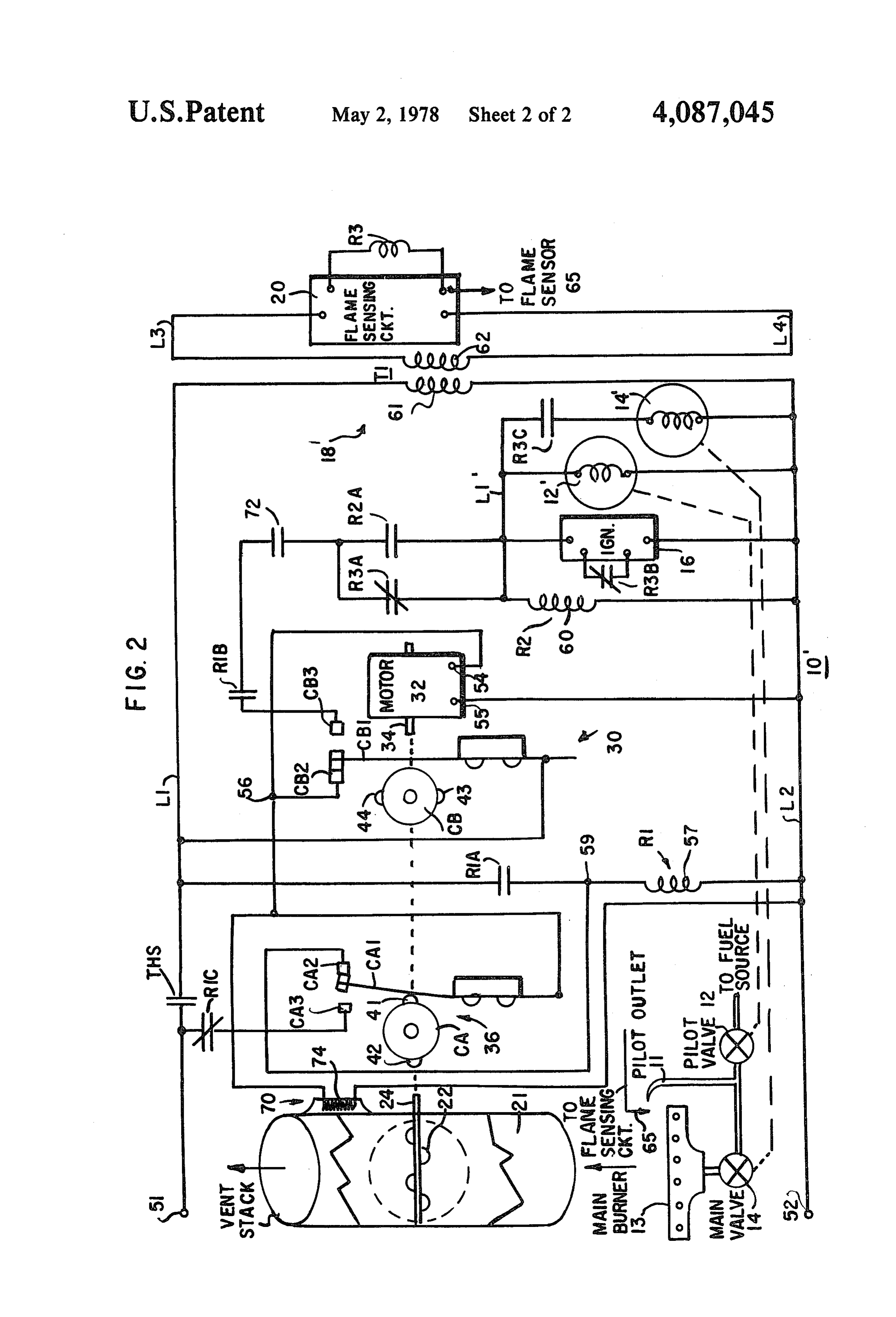
Referring to FIG. 2, there is shown a simplified rep cuit 18' to be effected over the limit switch 38 and resentation of a heating system 10" employing a control contacts REB and R3A in the manner described above arrangement provided in accordance with a second for heating system 10.
embodiment of the invention. The heating system 10' Accordingly, with contacts 72 closed, then when the shown in FIG. 2 is generally similar to the system 10 20 damper plate 22 has been driven to the fully open posi shown in FIG. 1, and accordingly, corresponding ele tion, limit switch 38 operates to energize the fuel igni ments have been given like reference numerals. tion control circuit 18", permitting the pilot valve 12 to The heating system 10' includes a fuel ignition con supply fuel to the pilot outlet 11 for ignition by sparks trol circuit 18' which controls the operation of fuel provided by the igniter circuit 16. Following ignition of valves 12 and 14, and a stack damper control circuit 30, 25 the pilot fuel, the flame sensing circuit 20 effects the including a drive motor 32 for driving damper plate 22 energization of the main valve 14 which operates to located in the vent stack 21 between open and closed supply fuel to the main burner 13 for ignition by the positions, and controlling the operation of limit pilot flame. The heater element 74, is deenergized when switches 36 and 38 for effecting the energization of the limit switch 38 operates, and begins to cool down. fuel ignition control circuit 18' in the manner described 30 However, when the main burner flame is established, above for the heating system 10. heat from the main burner 13 passing out the vent stack The fuel ignition control circuit 18' further includes a 21 maintains contacts 72 of the heat sensor switch 70 heat sensor switch 70 which responds to loss of main closed.
burner heat to deenergize the fuel ignition control cir If for any reason the main burner is not lit at the end cuit 18", preventing operation of the main valve 14 35 of the cooling time for the heater 74, contacts 72 open, under certain failure conditions. In particular, the heat deenergizing the fuel ignition control circuit 18, per sensor switch 70 effects the deemergization of the fuel mitting the fuel valves 12 and 14 to close. ignition control circuit 18' for an unsafe failure in the At the end of a successful heating cycle, contacts flame sensing circuit 20 during a heating cycle, fol THS open to deactivate the system 10' and permit the lowed by a flame-out or fuel interuption, thereby pre 40 damper plate 22 to be returned to the closed position as venting the supply of fuel to the main burner in the described above. When the main burner flame is extin absence of a pilot flame and with the igniter circuit 16 guished, the heat sensor switch 70 begins to cool down disabled. and, after a predetermined cooling time, permits More specifically, the heat sensor switch 70 com contacts 72 to open, and the system 10' is prepared for prises a thermal time delay relay, such as the Klixon 45 the next heating cycle.
Type A 60701 series. The switch 70, which may be In the event of a successful start-up followed by an mounted integral with the vent stack 21, as shown in unsafe failure in the flame sensing circuit 20, followed FIG. 2, in the heat exchanger, or adjacent the main by a flame out or fuel interruption, the main valve 14 burner 13, responds to heat from the main burner to may continue to supply fuel to the main burner. How control the operation of associated contacts 72. The 50 ever, the main burner and the exhaust stack 21 begin to contacts 72 are connected in series with contacts R1B of cool down due to the loss of main burner flame, permit the interlock relay R1 and contacts R3A of relay R3, in ting the heat sensor switch 70 to cool down. After the the energizing path for the fuel ignition control circuit cooling time for the switch 70, the contacts 72 of the 18'. heat sensor 70 open, interrupting the energizing path for The switch 70 has an internal heater 74 which has one 55 the fuel ignition control circuit 18", causing the fuel side connected to fixed contact CB2 of limit switch 38 valves 12 and 14 to closed interrupting the supply of and its other side connected to conductor L2, permit fuel to the main burner and the pilot outlet. Thus, the ting the heater 74 to be energized over limit switch 38 at heat sensor switch 70 in effect acts as a back-up flame the start of each heating cycle, and after a heating time sensor which deactivates the system 10' in the event of of approximately 15 seconds, causes contacts 72 to 60 the simultaneous failure conditions referred to above, or close. The heater 74 is deenergized when limit switch 38 for failure of the main burner to be lit within a predeter operates to energize the fuel ignition control circuit 18'. mined time following the operation of contacts THS in At such time, the heater 74 maintains the contacts 72 response to a request for heat.
closed for a predetermined duration to permit fuel sup I claim:
plied to the main burner 13 to be lit. When the main 65 1. In a heating system including a furnace having a burner flame is established, heat from the main burner fuel fired burner apparatus, fuel supply means operable 13 maintains the contacts 72 closed. In the absence of when energized to supply fuel to said burner apparatus the main burner heat, heater 74 cools down, and after a for combustion to provide heat, a vent stack for con 10 ducting combustion products away from said burner pilot valve means operable when energized to supply apparatus, and stack damper means including a stack fuel to a pilot outlet for ignition, and main valve means damper plate pivotally mounted within said vent stack, operable when energized to supply fuel to said burner said damper plate being normally maintained in a first apparatus for ignition by the pilot flame, a vent stack for position to close said vent stack and being rotatable to a conducting combustion products away from said burner second position to open said vent stack, and a drive apparatus, and stack damper means including a stack motor operatively coupled to said damper plate for damper plate pivotally mounted within said vent stack, driving said damper plate between said first and second said damper plate being normally maintained in a first positions, a control arrangement comprising switching position to close said vent stack and being rotatable to a means operable when energized to prepare an energiz 10 second position to open said vent stack, and a drive ing path for said fuel supply means, first limit switch motor operatively coupled to said damper plate for means connected in an energizing path for said drive driving said damper plate between said first and second motor to permit energization of said drive motor when positions, a control arrangement comprising switching ever said damper plate is at said first position, second means, first limit switch means connected in an energiz limit switch means connected in series with said first 15 ing path for said switching means and said drive motor limit switch means in an energizing path for said switch to permit energization of said switching means and said ing means to permit energization of said switching drive motor over said energizing path whenever said means whenever said damper plate is at said first posi damper plate is at said first position, activate means tion, activate means responsive to a request for heat to responsive to a request for heat to effect the energiza effect the energization of said switching means and said 20 tion of said switching means and said drive motor over drive motor over said energizing path including said said energizing path, including said first limit switch first limit switch means, when said damper plate is at means, when said damper is at said first position to said first position to permit said damper plate to be permit said damper plate to be driven towards said driven towards said second position, said second limit second position, said switching means being operable switch means being operated as said plate is driven 25 when energized to prepare an energizing path for said away from said first position to interrupt said energizing fuel supply means, and to provide a holding path for path for said switching means whereby said second limit said switching means, said first limit switch means being switch means prevents said switching means from re operable when said damper plate has been driven to said sponding to said activate means whenever said damper second position to interrupt said energizing path for said plate is at a position other than said first position, said 30 switching means and said motor drive and to complete first limit switch means being operable when said said energizing path for said fuel supply means, said damper plate has been driven to said second position to pilot valve means being connected to said energizing interrupt said second energizing path and to complete path for said fuel supply means for operation whenever said energizing path for said fuel supply means to effect said energizing path for said fuel supply means is com energization of said fuel supply means, said activate 35 pleted, said fuel supply means including flame sensing means being operable when the heating demand has means having a been met to deemergize said fuel supply means and said first switching device operable when energized to switching means, permitting said drive motor to be interrupt the energizing path for said fuel supply reenergized over a return path to drive said damper means, said fuel supply means including a second plate to said first position, said second limit switch 40 switching device connected to said energizing path means being operable when said damper plate has been for said fuel supply means and normally operable driven to said first position to interrupt said return drive prior to operation of said first switching device to path to effect the deenergization of said drive motor, provide a holding path for said pilot valve means, said switching means including a heat-sensor switch said first switching device being operable to con responsive to said activate means to permit the energi 45 nect said main valve means to said holding path for zation of said fuel supply means over said the energizing operation, said activate means being operable when path for said fuel supply means, said heat sensor switch the heating demand has been met to deemergize said being operable in the absence of heat from said main fuel supply means and said switching means, per burner apparatus within a predetermined interval of mitting said drive motor to be reenergized over a time following the energization of said fuel supply 50 return drive path to drive said damper plate to said means to interrupt the energizing path for said fuel first position, and second limit switch means opera supply means. ble when said damper plate has been driven to said 2. A system as set forth in claim 1 wherein said heat first position to interrupt said return drive path to sensor switch includes normally open contacts con effect the deenergization of said drive motor. nected in said energizing path for said fuel supply means 55 4. A system as set forth in claim 3 wherein said flame and a heater element energized over said first limit sensing means is energized responsive to said activate switch means responsive to said activate means to cause means, said first energizing path for said fuel supply said contacts to close, said heater element being deener means being interrupted by said switching device, pre gized when said first limit switch means is operated venting energization of said fuel supply means in the whereby said heat sensor switch maintains said contacts 60 event said first switching device operates prior to said closed responsive to heat from said burner apparatus, second switching device.
said heat sensor switch being operable in the absence of 5. In a heating system including a furnace having a heat from said burner apparatus within a predetermined fuel-fired burner apparatus, fuel supply means operable interval of time following deenergization of said heater when energized to supply fuel to said burner apparatus element to open said contacts to thereby deenergize said 65 for combustion to provide heat, a vent stack for con fuel supply means. ducting combustion products away from said burner 3. In a heating system including a furnace having a apparatus, and stack damper means including a drive fuel fired burner apparatus, fuel supply means including motor, and a damper plate pivotally mounted within 11 said vent stack, said damper plate being normally main said drive motor and operable to permit said first tained at a first position to close said vent stack and contacts to be maintained normally closed and said being rotatable to a second position to open said vent second contacts to be maintained normally open when stack, said drive motor being operatively coupled to said damper plate is at said first position, and for open said damper plate for driving said damper plate between ing said first contacts and closing said second contacts said first and second positions, a control arrangement when said damper plate is at said second position, and comprising switching means first limit switch means said second actuator means includes a second cam mem having first contacts for controlling the energization of ber coupled to said drive motor and operable to main said drive motor and second contacts for controlling the tain said third contacts normally closed and said fourth energization of said fuel supply means, said first limit 10 contacts normally open when said damper plate is at switch means being coupled to said stack damper means said first position, and for permitting said third contacts and operated thereby to close said first contacts to com to open and said fourth contacts to close when said plete an energizing path for said drive motor and to damper plate is at said second position. open said second contacts to prevent energization of 8. A system as set forth in claim 7 wherein said first said fuel supply means whenever said damper plate is at 15 and second contacts are operated by a common switch said first position, and second limit switch means having member whereby the energization of said switching third contacts for controlling the energization of said means and said drive motor is prevented in the event of switching means and fourth contacts connected in a a malfunction of said first limit switch means which return drive path for said drive motor, said second limit allows said first contacts to be open when said damper switch means being coupled to said stack damper means 20 plate is at said first position. and operated thereby to close said third contacts to 9. A system as set forth in claim 5 wherein said connect said switching means to said energizing path switching means comprises a switching device having for said drive motor, providing an energizing path for normally open contacts connected in said energizing said switching means over said first and second limit path for said fuel supply means and normally closed switch means, and to open said fourth contacts to inter 25 contacts connected in said return drive path for said rupt said return drive path when said damper plate is at drive motor.
said first position, activate means for connecting power 10. A system as set forth in claim 5 wherein said to said energizing paths to effect energization of said switching device comprises a relay having said nor switching means and said drive motor in response to a mally open contacts and said normally closed contacts request for heat, said switching means being operable 30 operated by a common armature whereby said normally when energized to complete an energizing path for said closed contacts are prevented from reclosing whenever duel supply means and to provide a holding path for said normally open contacts are welded together, said switching means, said drive motor being operable thereby preventing the reenergization of said drive when energized to drive said damper plate from said motor so that said damper plate is maintained at said first position to said second position, said stack damper 35 second position.
means operating said second limit switch means to 11. In a heating system including a furnace having a close said fourth contacts and to open said third fuel fired burner apparatus, fuel supply means operable contacts to interrupt said energizing path for said when energized to supply fuel to said burner apparatus switching means when said damper plate is driven for combustion to provide heat, a vent stack for con away from said first position, whereby said switch ducting combustion products away from said burner ing means is maintained energized over said hold apparatus, and stack damper means including a stack ing path, and said stack damper means operating damper plate pivotally mounted within said vent stack, said first limit switch means when said damper said damper plate being normally maintained in a first plate has been driven to said second position to position to close said vent stack and being rotatable to a open said first contacts to interrupt said energizing 45 second position to open said vent stack, and a drive path for said drive motor to deemergize said drive motor operatively coupled to said damper plate for motor and to close said second contacts to connect driving said damper plate between said first and second power to said energizing path for said fuel supply positions, a control arrangement comprising activate means to effect energization of said fuel supply means responsive to a request for heat to energize said means, said fuel supply means and said switching 50 drive motor to permit said damper plate to be driven to means being deenergized when the heating demand said second position, switching means including a heat has been met, permitting said drive motor to be sensor switch energized by said activate means to pre reenergized over said return drive path including pare an energizing path for said fuel supply means, limit said fourth contacts of said second limit switch switch means operable when said damper plate has been means to cause said damper plate to be driven to 55 driven to said second position to deemergize said motor said first position, said stack damper means operat and to complete said energizing path for said fuel supply ing said second limit switch means to open said means, said heat sensor switch being responsive to heat fourth contacts to interrupt said return drive path from said burner apparatus to maintain said energizing when said damper plate has been driven to said first path until the heating demand has been met, said limit position to deenergize said drive motor. switch means being operable in response to said drive 6. A system as set forth in claim 5 wherein said first motor driving said damper plate to said second position limit switch means has a first actuator means coupled to to deenergize said heat sensor switch to permit said heat said drive motor for operating said first and second sensor switch to interrupt said energizing path after a contacts, and wherein said second limit switch means predetermined time interval in the absence of heat from has a second actuator means coupled to said drive said burner apparatus within said predetermined time motor for operating said third and fourth contacts. interval, said activate means being operable when the 7. A system as set forth in claim 6 wherein said first heating demand has been met to deemergize said fuel actuator means includes a first cam member coupled to supply means, and to effect the reenergization of said 12 drive motor, permitting said damper plate to be re been driven to said first position to interrupt said return turned to said first position. drive path to effect the deemergization of said drive 12. A system as set forth in claim 11 wherein said heat motor.
sensor switch includes normally open contacts con 15. A system as set forth in claim 14 wherein, in the nected in said energizing path for said fuel supply event of a power interruption after said damper plate means, and a heater element energized over said limit has been driven to said second position, said switching switch means responsive to said activate means to cause means is effective to interrupt said energizing path for said contacts to close, said heater element being deener said fuel supply means and to prepare said return drive gized when said limit switch means is operated whereby path for said drive motor, permitting said drive motor said heat sensor switch maintains said contacts closed 10 to be reenergized when power is restored, causing said responsive to heat from said burner apparatus, said heat damper plate to be driven to said first position while sensor switch being operable in the absence of heat from maintaining said fuel supply means deemergized. said burner apparatus within a predetermined interval 16. A system as set forth in claim 14 wherein, said of time following deenergization of said heater element switching means comprises a switching device operable to open said contacts to thereby deemergize said fuel 15 when energized to close first contacts to prepare said supply means. energizing path for said fuel supply means and to close 13. A system as set forth in claim 11 wherein said heat second contacts to provide a holding path for maintain sensor switch is mounted in said vent stack. ing said switching device energized when said second 14. In a heating system including a furnace having a limit switch means operates.
fuel fired burner apparatus, fuel supply means operable 20 17. A system as set forth in claim 16 wherein said when energized to supply fuel to said burner apparatus second limit switch means is operable to prepare said for combustion to provide heat, a vent stack for con return drive energizing path for said motor when said ducting combustion products away from said burner damper plate is driven to said second position, said apparatus, and stack damper means including a drive switching device having third normally closed contacts motor, and a stack damper plate pivotally mounted 25 connected in said return drive path to interrupt said within said vent stack, said damper plate being normally return drive path when said switching device is ener maintained in a first position to close said vent stack and gized, said return drive path being completed by said being rotatable to a second position to open said vent third contacts when said switching device is deener stack, said drive motor being operatively coupled to gized, and said second limit switch means being oper said damper plate for driving said damper plate between 30 ated to interrupt said return drive path for said motor said first and second positions, a control arrangement when said damper plate is driven to said first position. comprising switching means, first limit switch means 18. A system as set forthin claim 17 wherein said first coupled to said stack damper means and operated and third contacts are operated by a common armature thereby to complete an energizing path for said drive whereby said third contacts are prevented from reclos motor to permit energization of said drive motor when 35 ing in the event said first contacts become welded to ever said damper plate is at said first position, and sec gether, thereby preventing said damper plate from ond limit switch means coupled to said stack damper being returned to said first position. means and operated thereby to connect said switching 19. A system as set forth in claim 14 wherein said first means to said energizing path for said drive motor, and second limit switch means are coupled to said drive providing an energizing path for said switching means motor for operation thereby.
over said first and second limit switch means when said 20. In a heating system including a furnace having a damper plate is at said first position, activate means fuel-fired burner apparatus, fuel supply means operable responsive to a request for heat for connecting power to when energized to supply fuel to said burner apparatus said energizing paths to effect the energization of said for combustion to provide heat, a vent stack for con switching means and said drive motor, said switching 45 ducting combustion products away from said burner means being operable when energized to complete an apparatus, and stack damper means, including a damper energizing path for said fuel supply means and to pro plate pivotally mounted within said vent stack, said vide a holding path for said switching means, said drive damper plate being normally maintained at a first posi motor being operable when energized to drive said tion to close said vent stack and being rotatable to a damper plate from said first position towards said sec 50 second position to open said vent stack, and a drive ond position, said stack damper means operating said motor operatively coupled to said damper plate for second limit switch means to interrupt said energizing driving said damper plate between said first and second path for said switching means when said damper plate is positions, a control arrangement comprising switching driven away from said first position, whereby said means operable when energized to prepare an energiz switching means is maintained energized over said hold 55 ing path for said fuel supply means and a holding path ing path, and said stack damper means operating said for said switching means, stack damper control means first limit switch means when said damper plate has including first limit switch means having first contacts been driven to said second position to interrupt said connected in an energizing path for said drive motor, energizing path for said drive motor to deemergize said and second contacts connected in an energizing path for drive motor and to connect power to said energizing 60 said fuel supply means, and a first actuator means in path for said fuel supply means to effect energization of cluding a first cam member coupled to said drive motor said fuel supply means, said activate means being opera and operable to permit said first contacts to be main ble when the heating demand has been met to deener tained closed and said second contacts to be maintained gize said fuel supply means and said switching means, open, providing an energizing path for said drive motor permitting said drive motor to be reenergized over a when said damper plate is at said first position to permit return drive path to drive said damper plate to said first said drive motor to be energized in response to a request position, and said stack damper means operating said for heat, second limit switch means having third second limit switch means when said damper plate has contacts connected in series with said first contacts in 13 an energizing path for said switching means, and fourth path for said drive motor to deemergize said drive motor contacts connected in a return drive path for said drive and to complete said energizing path for said fuel supply motor, and a second actuator means including a second means, said third and fourth contacts being operated by cam member coupled to said drive motor and operable a common switch member whereby the energization of to maintain said third contacts closed and said fourth 5 said switching means is prevented, thereby preventing contacts open when said damper plate is at said first the energization of said fuel supply means in the event position, permitting energization of said switching of a malfunction of said second limit switch means means over a path including said first and third contacts which permits said third contacts to be open when said in response to a request for heat, said drive motor being damper plate is at said first position, said fuel supply operable when energized to drive said damper plate 10 means and said switching means being deemergized from said first position to said second position, said second limit switch means being operated to open said when drive the heating demand has been met, permitting said motor to be reenergized over said return drive third contacts and close said fourth contacts when said path, including said fourth contacts, to cause said damper plate is driven away from said first position to damper plate to be driven to said first position, said interrupt said energizing path for said switching means 15 second limit whereby said switching means is maintained energized switch means being operated when said over said holding path, and said first limit switch means damper plate has been driven to said first position to being operated when said damper plate has been driven open said fourth contacts to deenergize said drive mo to said second position to open said first contacts and to tOr, : sk close said second contacts to interrupt said energizing 20
Page 14scan →
United states patent and tfademark office
Certificate of correction
INVENTOR(S) : Russell Byron Matthews it is Certified that error appears in the above-identified patent and that said Letters Patent are hereby corrected as shown below:
O Column 13, line 46, cancel 'said's econd occurrence; Column 14, line 57, cancel 'first';
Column 15, line 7, insert a comma before 'first';
Column 15, line 32, "duel' should be -- fuel -- ;
O signed and Sealed this
Seal
Twelfth Day of September 1978
Attesting Officer Commissioner of Patents and Trademarks
Provenance
- Collection
- Patents citing this work
- Pages
- 14
- Method
- pdftotext (the PDF's own text layer) + pdftoppm 300dpi page scans
- Patent office record
- patents.google.com →
- Source
- Google Patents citing-documents table
- Assignee
- Johnson Controls, Inc.
- Published
- 1978-05-02
- Transcribed from
- patentimages.storage.googleapis.com →