

patent · US4088115A
Solar heating system
9 May 1978
Text
Page 1bibliographic recordscan →
United States Patent (19)
Powell
(54). SOLAR HEATING SYSTEM
76 Inventor: Charles E, Powell, 15510 Tonekai
Rd., Apt. F, Apple Valley, Calif.
Int. Cl’................................................. F24, 3 52 U.S.C. .................................... 126/270; 237/1 A
3,894,685 7/1975 Keyes et al.......................... 237/1 A 4,018,212 4/1977 Barr...................................... 126/271 4,030,477 6/1977 Smith ................................... 126/270 Primary Examiner-Kenneth W. Sprague
Attorney, Agent, or Firm-Fred N. Schwend
A solar heating system including a large number of nested thin wall cylindrical collector-convertors dis posed in vertical positions and housed within an insu lated housing having a window therein to allow light rays from the sun to strike the collectors at any of differ ent angles regardless of the latitude or altitude of the sun. Ultraviolet and other shorter wave length rays are converted into heat upon striking the inner surfaces of
the collectors to heat the walls thereof, and infra-red and other longer wave length rays are absorbed by coatings on the collectors to likewise heat the walls thereof. Those rays which are reflected strike the oppo site collector wall surfaces to again be converted to heat. The collectors are of such length as to enable multiple reflections under practically all conditions. Air to be heated is passed lengthwise along the outer wall surfaces of the collectors to pick up the heat therefrom and is then passed to a heat storage device under certain temperature conditions where it is stored for future use. The heat storage device is constructed of stacked ce ment plates having labyrinth passages therein through which the heated air is passed to heat the concrete. Air for heating a building or the like is passed through other labyrinth passages within the heat storage device to absorb heat therefrom.
An automatically controlled valve system controls the passage of heated air between the collector-converter housing, the heat storage device and a building struc ture to be heated in different manners depending upon the relative temperature conditions existing within the building, the collector-convertor unit and the heat stor age device.
11 Claims, 22 Drawing Figures
y sea
Drawings
Page 2drawing sheetscan →
Page 3drawing sheetscan →
Page 4drawing sheetscan →
Page 5drawing sheetscan →
Page 6drawing sheetscan →
Page 7scan →
Solar heating system
sure having a panel of heat insulating material over which is mounted a large number of nested thin walled
BACKGROUND OF THE INVENTION cylindrical collector-convertor members which are 1. Field of the Invention 5 formed of metal, preferably aluminum. Such members This invention relates to a solar heating system and have a length-to-diameter ratio of from 2:1 to 3:1 and has particular reference to a system for collecting and are covered with a thin black selective coating. The converting the sun's rays to heat and to transfer such enclosure is mounted in a substantially horizontal posi heat to a building or like structure. tion with the collector-convertor members extending 2. Description of the Prior Art 10 vertically, and a transparent window forming part of Heretofore, solar heating systems have generally the enclosure is spaced from the upper ends of the col utilized so called "flat plate' collectors comprising a lector-convertor members, permitting rays from the sun heat absorbent plate within an enclosure formed partly to strike the walls of the members.
by a transparent window which allows the sun's rays to Accordingly, practically regardless of the position of pass through the enclosure and to strike the plate. Air, 15 the sun in altitude and at all times of the day, the sun's or other heat absorbing fluid, is passed through the rays will strike the inner wall surfaces of the members at enclosure and along the plate to transfer heat thereto an angle. The ultraviolet and other short wave length from the plate. rays will pass through the outer coating and most will In order to increase the efficiency of such systems, be converted into heat to heat the walls of the members. recent developments have comprised the addition of 20 The infrared and other longer wavelength rays will be heat absorbing bodies such as shredded material or absorbed by the coating to also heat the walls. Those partitions within the flat plate enclosure to increase the rays which are reflected will strike an opposite wall area exposed to the sun. The U.S. Pat. No. 3,946,720 surface of the member and again, the main body thereof issued to J. H. Keyes et al. discloses an example of this will be converted to heat. This will continue until sub type. 25
Ideally, collectors of the above flat plate type should stantially heat. Heat all of the sun's rays have been converted to radiated from any surface will be absorbed, track the sun as it passes across the horizon to maintain at least partly, by an opposite wall. the greatest thermal efficiency throughout the day. By forming the end walls of the collector-convertor However, because of the cost and complexities encoun members in a convex tered in moving such a collector, it is generally set in a substantially none of theorsurfaces 30 otherwise non-planar form, of the members face stationary position at such an angle that it will be per pendicular to the sun at about 1300 hours, solar time. outward and therefore only a minute amount of heat, if Obviously, the efficiency of such a collector falls off any, will be radiated outwardly through the window. considerably as the sun moves away from such perpen According to another aspect of the invention, the dicular position. Also, much of the heat from a flat plate 35 heat insulating panel of the collector-convertor unit is collector is radiated outwardly through the window, provided with relatively small holes therethrough, such further reducing its efficiency so that, at best, such holes being located intermediate the outer sides of adja collectors are generally considerably less than 50% cent ones of the various collector-convertor members. efficient. Air is forced between the window and the tops of the 40 members, causing the same to turbulate and to flow
Summary of the invention
downwardly along the lengths of the members through
A principal object of the present invention is to such holes to a collector manifold chamber below the greatly increase the efficiency of a solar heating system panel. As the turbulent air moves along the outer sur for buildings or the like.
Another object is to provide a solar heating system 45 facesthe of the members, it picks up heat therefrom. Since air is turbulent as it passes along the members, any capable of deriving heat from the sun during periods of tendency toward laminar flow is eliminated and since cloudy or overcast days as well as during sunny days.
Another object is to reduce the size and cost of a solar the holes in thepressure the air is under panel, because of the restrictive size of a high degree of heat transfer heating system.
Another object is to provide a solar heating system 50 OCCS. Air from the collector manifold chamber is automati which will maintain a relatively high degree of effi cally transferred through conduit means to either a heat ciency throughout a large portion of the daylight hours. storage unit or directly to the building or is recirculated Another object is to provide a solar heating system within the collector-convertor unit or is transferred capable of collecting and converting to heat all of the sun's rays ranging from ultraviolet to infra red. 55 from the heat storage unit to the building, all depending Another object is to provide an improved heat stor parts upon the temperature conditions existing in different age device for a solar heating system. of the system.
Another object is to provide aheat storage device for The heat storage unit is of modular design comprising a solar heating system which may be readily expanded a plurality of stacked plates of concrete or the like hav or contracted to meet the heat storage needs of build ing aligned holes therein arranged to form a plurality of ings or other structures of different sizes or heat de labyrinth passages for uniformly absorbing heat from mands. the heated air and transferring such heat to other laby A further object is to provide an improved control rinth passages in which air to be heated is passed for system for controlling the transfer of heat between a conveyance to the building or other structure to be solar heat collector, a heat storage device and a building 65 heated. The volumetric content of the heat storage unit or the like to be heated. may be readily varied in accordance with the heat stor According to the present invention, a solar heat col age requirements by varying the number of plates lector-convertor unit is provided comprising an enclo within the stack.
Page 8scan →
Brief description of the drawings description of the preferred
Embodiment
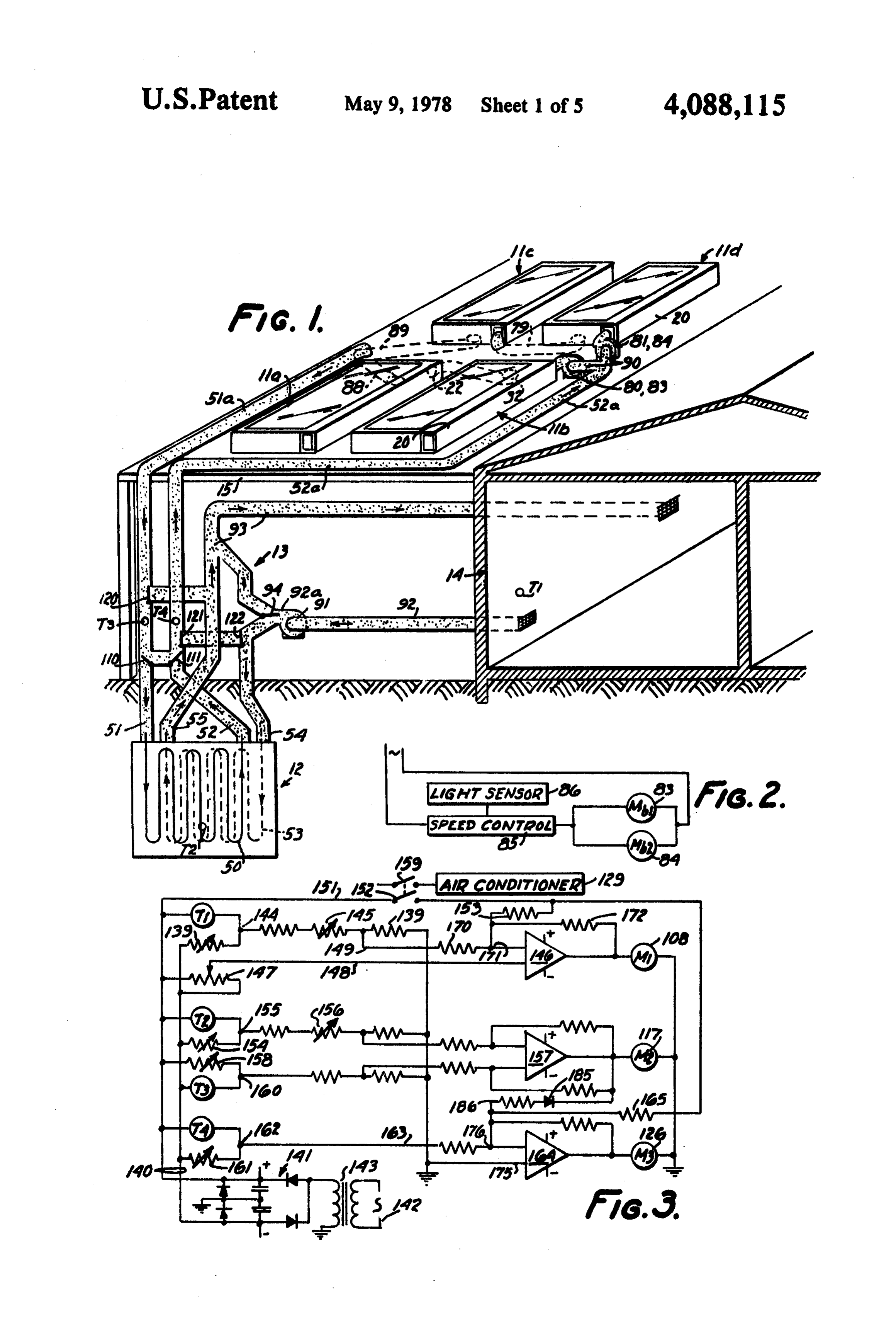
The manner in which the above and other objects of the invention are accomplished will be readily under Referring in particular to FIG. 1, the solar heating stood on reference to the following specification when 5 system, in general, comprises a heat collecting device 11 read in conjunction with the accompanying drawings, including a series of collector-convertor units 11a, 11b, wherein: 11c, and 11d, a heat storage unit 12 and a valve control FIG. 1 is a schematic perspective view of a solar system 13 for controlling the flow of air between the heating system embodying a preferred form of the pres above elements and the interior of a building 14 in ac ent invention, 10 cordance with different temperature conditions and FIG. 2 is a schematic wiring diagram of the control requirements.
circuit for the blower motors for circulating air through COLLECTOR-CONVERTOR UNITS the collector-convertor units.
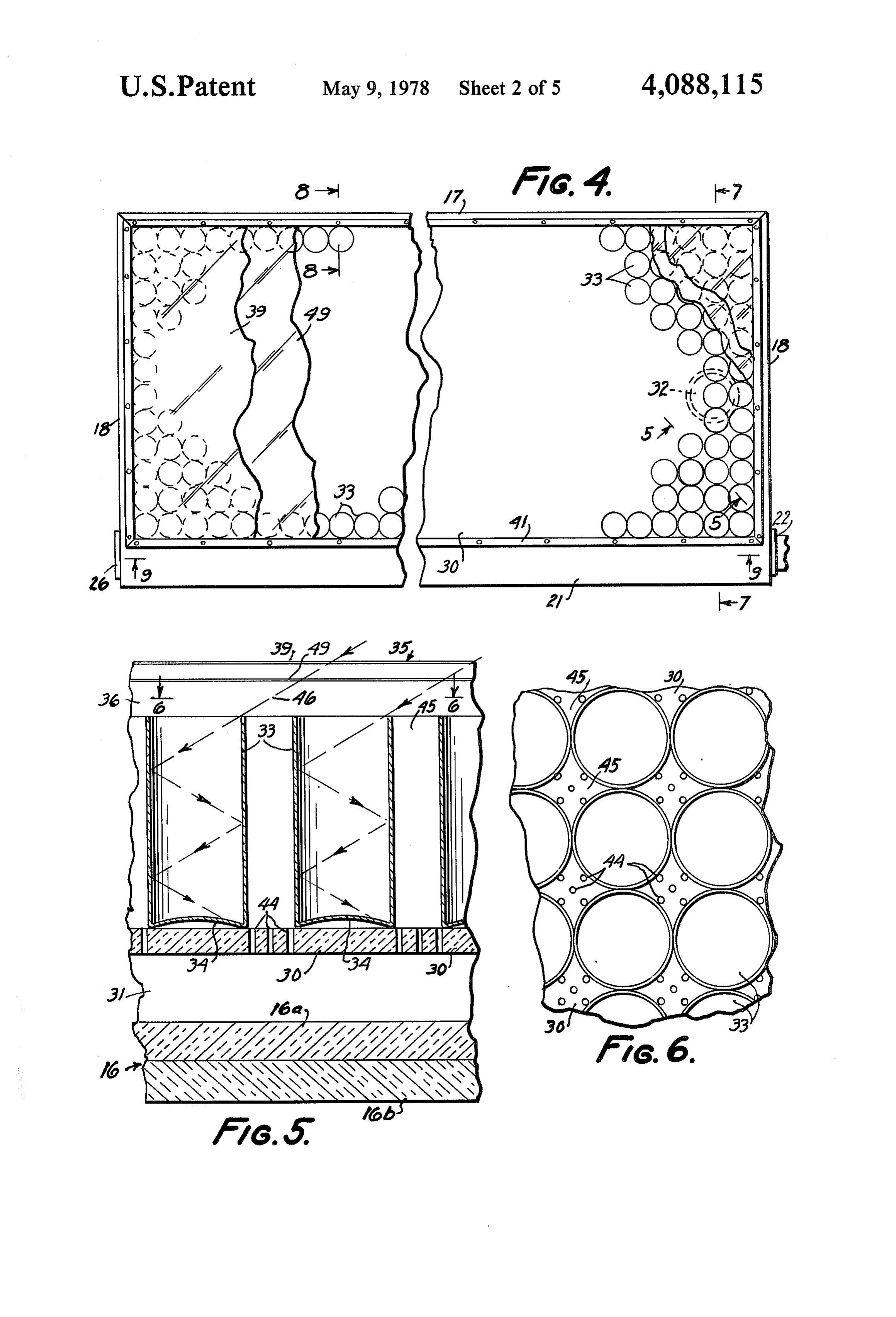
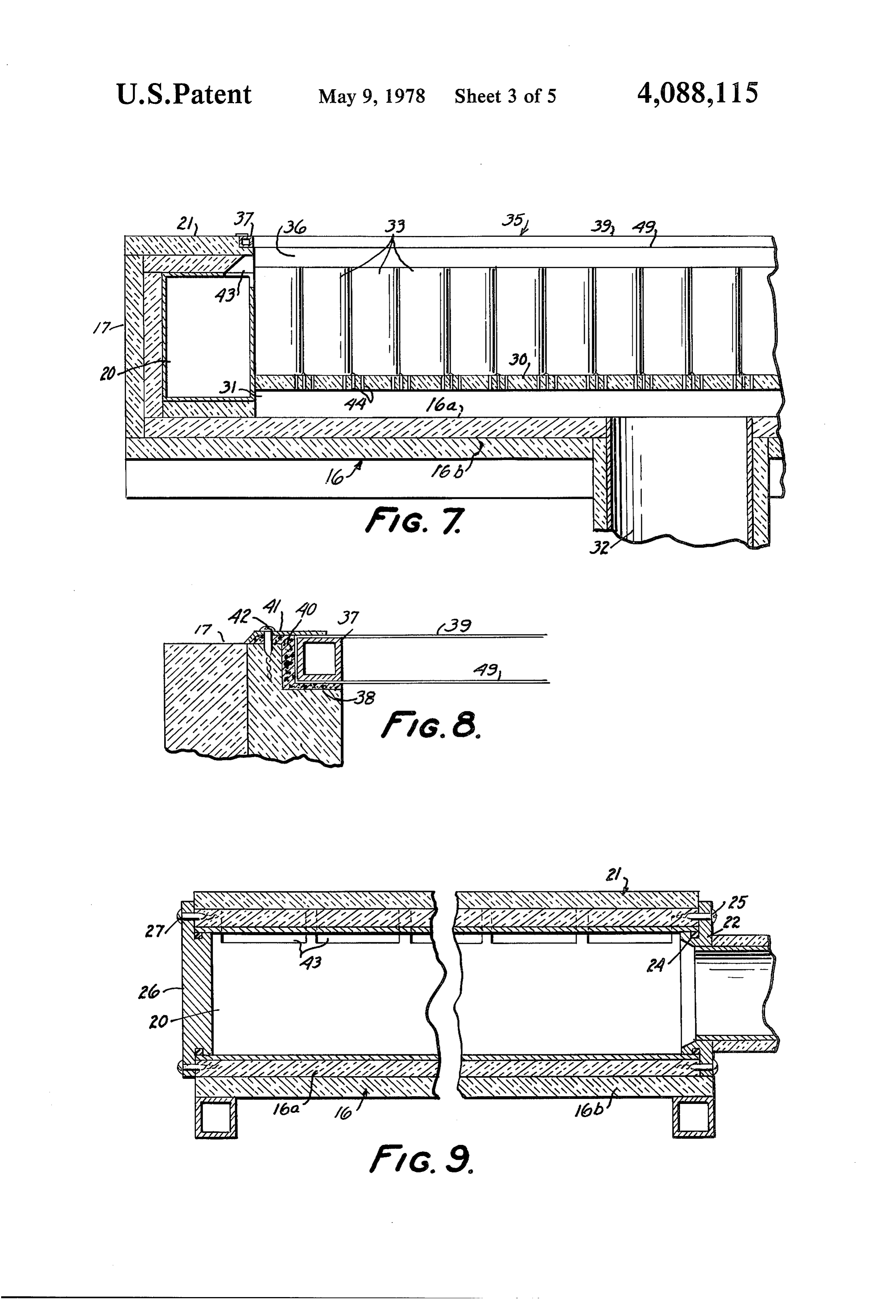
FIG. 3 is a schematic wiring diagram of the valve Describing now the construction of the collector control circuits for controlling air flow between the 15 convertor units 11a to 11d, such units are of similar collector-convertor units, the heat storage device and construction but may vary in number depending upon the building. the maximum heat required for the building 14. Al FIG. 4 is a plan view, partly broken away, of one of though the units 11a, etc., are illustrated as being the collector-convertor units. mounted in elevated horizontal positions on a roof FIG. 5 is an enlarged sectional view taken along line 20 structure 15 adjoining the building 14, they may alter 5-5 of FIG. 4. nately be mounted on the ground or on a separate struc FIG. 6 is a sectional plan view taken along line 6-6 ture spaced from the building. Also, if the roof of build of FIG. 5. ing 14 were horizontal, the units 11, etc., could be FIG. 7 is a transverse sectional view through one of 25 mounted thereon, the collector-convertor units and is taken along the line As shown in FIGS. 1 and 4 to 9, each collector-con 7 7 of FIG, 4. vertor unit comprises a base 16 formed of two layers FIG. 8 is an enlarged fragmentary sectional view 16a and 16b of heat insulating material, such as com showing part of the window frame and is taken along pressed fiberglass, rigid polyurethane foam or the like. the line 8-8 of FIG. 4. 30 Side and end walls 17 and 18, respectively, also formed FIG. 9 is a sectional view through the inlet manifold of insulating material surround the base 16 forming part of one of the collector-convertor units and is taken of the enclosure for the collector-convertor unit. An along the line 9-9 of FIG. 4. inlet manifold 20 of rectangular cross section is formed FIG. 10 is a front view, partly in section, of the heat of sheet metal which is fitted along one of the side walls storage unit and is taken substantially along line 10-103s 17 and is covered by a top member 21 also of two layers of FIG. 11. of insulating material.
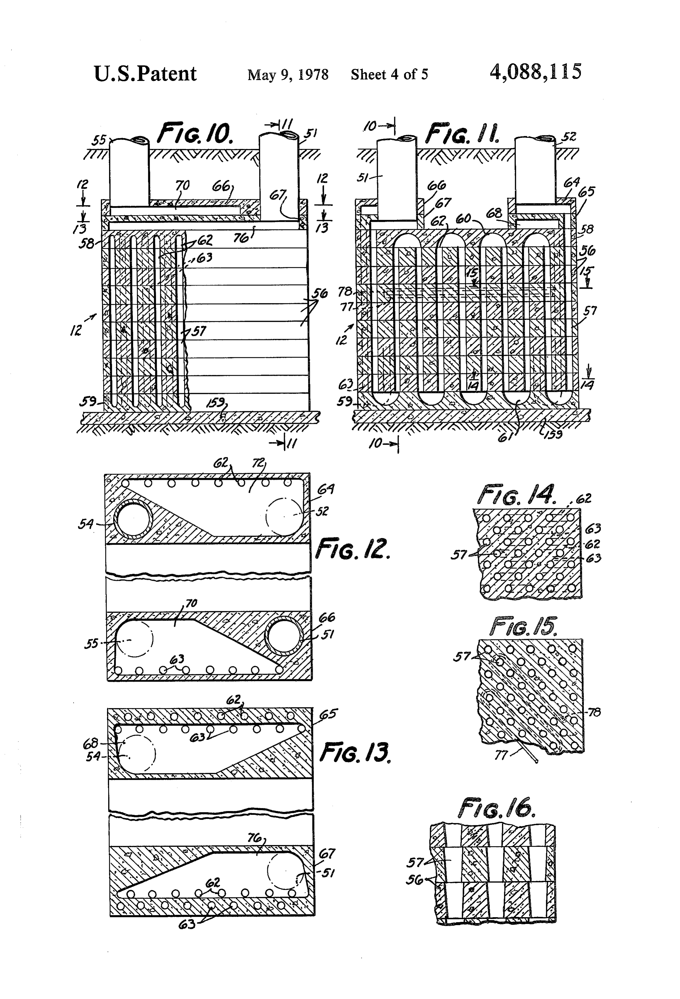
FIG. 11 is a side sectional view taken along line A flanged inlet fitting 22 (FIG. 9) is connected to one 11-11 of FIG. 10. end of the manifold 20 and partly fits within the mani FIG. 12 is a sectional plan view through the upper fold. A sealing ring 24 fitted within a groove in the manifold plates and is taken along line 12-12 of FIG. 40 fitting 23 provides a hermetic seal and screws 25 secure 10. the flanged portion of the fitting to walls surrounding FIG. 13 is a sectional plan view through the lower the end of the manifold 20.
manifold plates and is taken along line 13-13 of FIG. The opposite end of the manifold 20 is closed by a 10. flanged cap 26 which is secured by screws 27 to the FIG. 14 is fragmentary sectional plan view through 45 walls surrounding the manifold 20. Since both ends of one of the heat storage plates and is taken along line the manifold 20 are alike, the fitting 23 and the cap 26 14-14 of FIG. 11. may be interchanged to facilitate any desired grouping FIG. 15 is a fragmentary sectional plan view taken of the collector-convertor units.
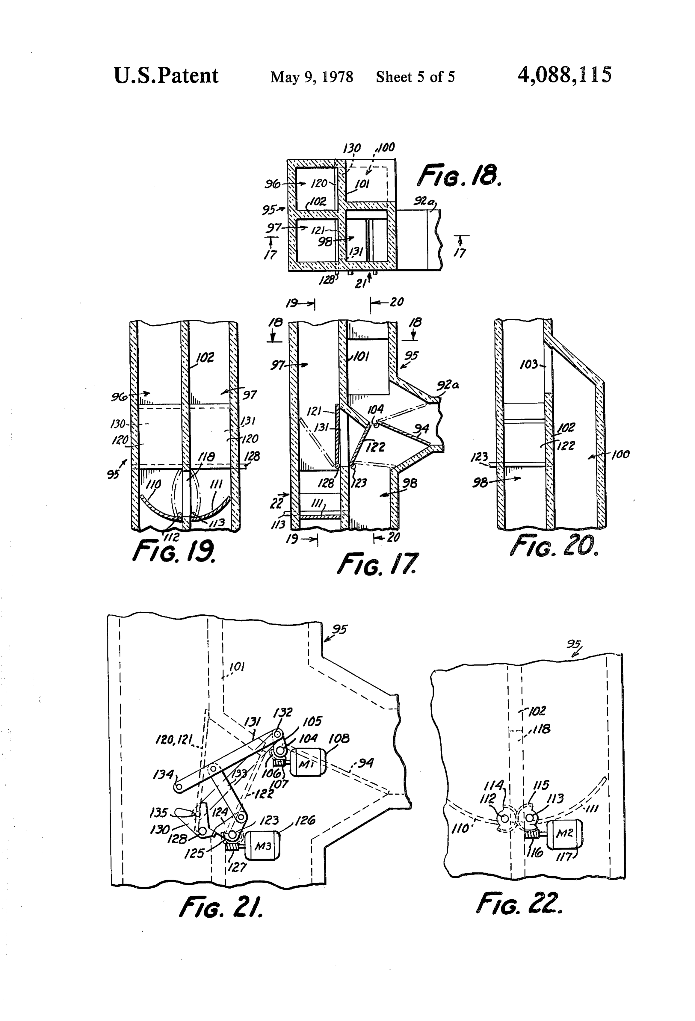
along line 15-15 of FIG. 11. As shown in FIGS. 4, 5 and 7, a panel 30 of heat FIG. 16 is an enlarged fragmentary sectional view 50 insulating material, such as fiber board, is fitted within through certain of the air passages in the heat storage the side and end walls 17 and 18, respectfully, of the unit device. 11 and is suitably secured in spaced relation to the base FIG. 17 is a sectional front view through the valve 16 to form an outlet manifold chamber 31. An outlet device embodying the servo, bypass and changeover conduit 32 opens into such chamber for removing valves, and is taken along line 17-17 of FIG. 18. 55 heated air therefrom.
FIG. 18 is a sectional plan view of the valve device In accordance with the present invention, a plurality and is taken along line 18-18 of FIG. 17. of cylindrical collector-convertor members 33 are FIG. 19 is a sectional left hand side view of the valve nested within the walls 17, 18 and rest on the panel 30. device and is taken along line 19-19 of FIG. 17. Such members 33 are formed of thin aluminum, prefera FIG. 20 is a sectional right hand side view of the bly on the order of 0.015 inches thick, and are closed at valve device and is taken along the line 20-20 of FIG. their lower ends by integrally formed upwardly convex 17. end walls 34. The members 33 are black anodized or FIG. 21 is a front view, with parts broken away, of otherwise formed with a thin selective black coating on the valve device and is taken in the direction of the all surfaces thereof which will allow ultraviolet and arrow 21 of FIG. 18. 65 other rays of shorter wave lengths from the sun to pene FIG. 22 is a left hand side view, with parts broken trate the same and to be converted into heat upon strik away of the valve device and is taken in the direction of ing the metal walls of the members 33, thus heating the the arrow 22 in FIG. 17. walls of such members. The coating will also absorb 9 infrared and other longer wave length rays to likewise the sun's path to obtain a large number of reflections, heat the walls of members 33. particularly during midday.
It will be noted that the members 33 are at least twice The upper surface of the insulating panel 30 is prefer as long as their diameters and may optimally be from 2 ably coated with a white substance so that practically to 3 times as long as their diameters. no heat will be radiated outward therefrom. A transparent window, generally indicated at 35, is Air to be heated is admitted under pressure through fitted over the top opening between the side walls 17 the manifold 20 to the space 36 above the members 33. and 18 and is located above the upper ends of the mem As it passes through the collector-convertor unit it will bers 33 to form an air space 36. For this purpose, a be turbulated by engagement with the relatively sharp rectangular metal frame 37 (FIGS. 4, 7 and 8) of rectan 10 upper edges of the various members 33 and will then gular cross section is fitted within notched portions 38 pass downwardly along the outer surfaces of such mem formed in the side walls 17 and 18. Two relatively thin bers, picking up heat along the entire lengths thereof. sheets of transparent plastic 39 and 49, preferably poly Thereafter, such heated air will pass downwardly vinyl flouride, are stretched over the top and bottom through the holes 44 in panel 30 and into the outlet edges of the frame 37, leaving a heat insulated space 15 manifold chamber 31. The holes 44 preferably comprise therebetween. Such plastic sheets 39 and 49 may be only approximately 2 percent of the total area of the bonded together at their outer edges or may be bonded panel 30 so that they form a restriction to retard the to the frame 37. The frame 37 is set in a soft mastic 40 flow of air through the panel. Thus, the air within the and is held in place by a retainer strip 41 secured to the unit 11 is compressed to force the same into intimate upper edges of walls 17 and 18 by screws 42. 20 contact with the members 33 throughout their lengths As seen in FIGS. 7 and 9 in particular, openings 43 to better remove the heat therefrom. Since any laminar are formed along the length of the manifold 20 and top flow of the air is prevented by virtue of the turbulence wall 21 to communicate the interior of the manifold 20 thereof as it passes over the edges of the members 33, with the air space 36, permitting the air to flow uni the air will remove essentially all heat contained in the formly over the tops of the various members 33. 25 walls of such members. Also, due to such compression, Relatively small holes 44, FIGS. 5, 6 and 7, are the air will be uniformly distributed throughout the formed through the insulating panel 30 to communicate space 36.
the spaces 45 between the outside surfaces of adjacent members 33 with the outlet manifold chamber 31. HEAT STORAGE UNIT In operation, since the collector-convertor unit is in a 30 Describing now the heat storage unit 12, it should be horizontal position, the sun's rays passing through the noted that the latter has two series of labyrinth passages, window 35 at an angle of, for example, 35' as indicated one separated from the other. The first series is depicted by the arrows 46, FIG. 5, will mainly strike the inner schematically in FIG. 1 by solid serpentine lines 50 surfaces of the members 33. The longer wave length connected to conduits 51 and 52 to carry air to and from waves will be predominately absorbed by the coating the unit 12 to heat the same. A second series of labyrinth on the members and some will be reflected to the oppo passages is depicted by the dotted serpentine line 53 site inner sides of the members. Likewise, the shorter which is connected to conduits 54 and 55 for conveying wave length rays will pass through the coating and be air to be heated by the unit 12 to and from the same. predominately absorbed by the inner side walls of the Referring to FIGS. 10 to 16, the heat storage unit 12 members 33 and some will be reflected. This continued 40 comprises a stack of horizontally extending plates 56 absorption and reflection will continue until the rays are formed of heat absorbing and retaining concrete and substantially completely absorbed to heat the walls of layed on top of one another, the stack being preferably the members. located under ground. As seen in FIGS. 10, 11, 14 and Since the bottom walls 34 of the members 33 are 16, each of the plates 56 has a series of holes 57 extend convex, substantially all of the sun's rays which might ing therethrough which are regularly spaced in orthog strike the same either directly or from reflection will be onal directions and combined to form vertically extend reflected off to the side walls and substantially none will ing spaced passages extending through the entire stack. be reflected outwardly through the window 35. Like Additional plates 58 and 59, also of concrete, are lo wise, any heat radiated by the inside or outside surfaces cated at the top and bottom of the stack and have return of the members 33 will strike an opposite surface of the 50 end grooves 60 and 61, respectively, formed therein same or an adjacent member 33 and practically none which bridge across adjacent pairs of the passages in will be radiated back through the window 35 into space one direction to form a series of parallel passageways 62 since heat will radiate only in a direction normal to the and 63 of serpentine form. The entire stack rests on a radiating surface. base plate 159 also of concrete and a moisture proof It will be seen from the above that in most latitudes 55 cover of plastic or the like (not shown) is preferably and at most times during daylight hours, the sun's ray placed over the stack.
will be reflected several times between the inner sur It will be noted, as seen particularly in FIGS. 10 and faces of the members 33 to collect a maximum amount 14, that the various passageways 62 and 63 are located of solar energy. In fact, at higher latitudes and in early in two separated groups corresponding to the schematic morning and late afternoon when the sun's rays are representations 50 and 53, respectively, in FIG. 1, That attenuated mostly because of the greater distances they is, one group 62 is located in alternate parallel planes must travel through the earth's atmosphere, a greater and the other group 63 is located in alternate parallel number of reflections will take place to insure maximum planes interspersed with but separated from group 62, collection of solar energy even under those conditions. Also, as seen in FIG. 11, the passageways 62 are stag On the other hand, in order to obtain a greater number gered relative to the passageways 63. of reflections in lower latitudes, approaching 0' latitude, Manifold plates 64, 65, 66 and 67, also of concrete, are it may be desirable to tilt the collector-convertor units provided to connect the inlets of respective groups 62 slightly away from the perpendicular and away from and 63 of the passageways together and to also connect 10 the outlets of such groups together and to respective The blower 91 is preferably operated continuously ones of the conduits 51, 52, 54 and 55. The manifold but may be switched on and off under manual control plates are located in pairs as seen in FIGS. 11, 12 and 13. through a conventional circuit, not shown. The lower plate 65 has a cavity 68 communicating the VALVE SYSTEM inlet ends of passageways 63 with the conduit 54. The 5 other or outlet ends of the passageways 63 extend The valve system 13 is responsive to certain tempera through manifold plate 67 and open into a cavity 70 ture conditions in different locations, as sensed by dif formed in the upper manifold plate 66 to communicate ferent temperature sensing devices T1 to T4, and is the same with the conduit 55. On the other hand, upper effective to appropriately direct the flow of air between manifold plate 64 has a cavity 72 which communicates the collector-convertor units 11a–11d, the heat storage the outlet ends of passageways 62 with the conduit 52. unit 12 and the building 14 in accordance with the rela The manifold 67 has a cavity 76 therein which commu tive temperatures determined by such sensors. Sensor nicates the inlet ends of passageways 62 with the con T1 senses the ambient temperature inside the building duit 51. 14 at a location adjacent the air outlet conduit 92; sensor As seen in FIG. 16, the various holes 57 in the plates 15 T2 senses the temperature in the heat storage unit 12; 56 are tapered slightly to form an irregular passage. sensor T3 senses the temperature in the conduit 51a and Therefore, as air is forced therethrough, either to heat sensor T4 senses the temperature in the conduit 52a. the same or to remove heat from the storage unit, such The valve system 13 is shown schematically in FIG. air is turbulated to break up any laminar flow tendency 1 as being formed of separate conduits and valves for in order to effect a high degree of heat transfer between 20 the sake of clarity and for understanding the function of the air and the plates 56. the same. However, as seen in FIGS. 17 to 22, the valve The heat storage unit 12 may be utilized to supply system is actually consolidated into a single valve de heat for purposes other than heating the interior of the vice to which the various conduits 51, 51a, 52, 52a, 54, building 14. For this purpose, one or more of the plates 55, 92 and 93 are connected. The valve device com 56 may have a copper or the like tubing 77, FIGS. 11 25 prises an elongate tubular member 95 which is square in and 15, cast therein. The tubing is bent back upon itself cross section and is divided into four valve chambers 96, as seen at 78 and is wound in a sinous manner through 97, 98 and 100 by intersecting divider walls 101 and 102. the plate to pass adjacent various ones of the holes 57. The walls of member 95 and the divider walls 101 and Fluid, such as water, is heated by passage through the 102 are preferably formed of a heat insulating material tubing 77 and may be used to supply hot water within 30 to prevent transfer of heat therethrough. Also, the vari the building or to heat different appliances, etc. ous conduits, i.e. 51 etc., are also suitably heat insulated
Air circulating apparatus
for the same purpose.
Valve chamber 96 connects conduits 51 and 51a.
In order to circulate air through the collector-con Chamber 97 connects the conduits 52 and 52a. Chamber vertor units 11a to 11d, air blowers 80 and 81, FIG. 1, 35 98 connects the blower outlet 92a to either the conduit are provided at the inlets to the inlet manifolds 20 of the 54 at the lower end of the chamber or to conduit 93 at units 11b and 11d. Motors 83 and 84, see also FIG. 2, for the upper end of the chamber or partially to both, de respective ones of the blowers 80 and 81, are connected pending on the position of the aforementioned servo in circuit with a suitable speed control unit 85 which is valve 94. Chamber 100 connects conduit 55 to the upper controlled by a light senser 86 which senses the ambient 40 end of chamber 98 and thus to conduit 93 through an outside light and causes the blowers 80 and 81 to force opening 103 in the divider wall 102. a quantity of air through the units 11b to 11d in propor Servo valve 94 controls the amount of heat applied to tion to the intensity of outside light. Thus, during night the interior of the building 14 from either the heat stor time hours, the motors 83 and 84 are at rest and no air age unit 12 or directly from the collector-convertor is passed through the units 11b and 11d, while during 45 units 11a-11d or causes recirculation of some or all of midday on a cloudless day, a maximum amount of air is the air within the building, and for this purpose it is passed through the units. movable between its fully closed position shown in full As seen in FIG. 1, the outlet conduit 32 of collector lines in FIG. 17 and its fully open position shown in convertor unit 11b is connected to the inlet conduit dot-dash lines or it is movable to any position immediate fitting 22 of unit 11a and the outlet conduit, i.e. 32, of 50 such extremes. Valve 94 is carried by a rockable shaft the latter is connected through a branch conduit 88 to a 104, see also FIG. 21, to which is attached an arm 105 conduit 51a forming an upper extension of conduit 51. and a worm gear sector 106, the latter meshing with a The units 11c and 11d are similarly connected together worm 107 driven by a reversible motor 108. Control of and to the conduit 51a through conduit 79 and branch the motor 108 in response to temperature variations conduit 89. 55 sensed by sensor T1 will be described subsequently. The inlets of the blowers 80 and 81 are connected Arcuately shaped bypass valves 110 and 111 are pro through branch conduits 90 to a conduit 52a forming an vided in the chambers 96 and 97, respectively, for the upper extension of the conduit 52. purpose of either recirculating the heated air within the An additional motor driven blower 91 is provided to collector-convertor units 11a–11a when the tempera withdraw air from the interior of the building 14 ture of such air is lower than the temperature of the heat through conduit 92, opening into the building, and to storage unit 12 or transferring such air between the force the same through an outlet 92a into either the storage unit 12 and the units 11a–11a when the tempera conduit 54 leading to the storage unit 12 to be heated or ture of such air in the units 11a-11d is higher than the through a conduit 93, also opening into the building, to temperature of the unit 12.
recirculate the same through the building or to force the 65 Valves 110 and 111 are carried by respective rockable air through both such conduits in different proportions shafts 112 and 113, see also FIG. 22, for movement depending on the setting of a variable position servo between closed positions shown in full lines in FIG. 19 valve 94 which will be described later. and open positions shown by dot-dash lines. Intermesh 11 ing gear sectors 114 and 115 are secured to the shafts to the building 14. In this condition, as determined by 112 and 113 respectively. Sector 115 also meshes with a temperature sensor T4, the changeover valve 122 will worm 116 driven by a reversible motor 117. Control of be moved fully to its closed position. Accordingly, air the motor 117 in response to temperature differentials from the building 14 passing through conduit 92, will be determined by sensors T2 and T3 will be described directed, at least in part, by the servo valve 94 to pass subsequently. However, it should be noted here that over the now closed changeover valve 122, through when the by-pass valves 110 and 111 are in their closed opening 131, and upwardly over now opened auxiliary positions, air passing downwardly through the chamber servo valve 121 into chamber 97 from whence it is 96 from the collector-convertor units 11a-11d will be deflected laterally through an opening 118 in the di 10 conducted through conduit 52a to the collector-conver tor units 11a-11d. Heated air from the units 11a-11d, on vider wall 102 and will be returned upwardly through the other hand, will be transferred from the conduit 51a the chamber 97 to recirculate through the units 11a -11d, thereby causing reheating of the air until its tem to chamber 96 and then deflected laterally by the now opened auxiliary servo valve 120 through the opening perature rises above that of the storage unit 12 at which 130 in divider wall 101 into chamber 100 to be con time the valves 110 and 111 are moved to their open 15 ducted positions, closing off the opening 118 and permitting the 93 and, upwardly therefore, through chamber 98 and into conduit into the building 14. The control of heated air to pass directly between the units 11a–11ad valve 122 in response to temperatures determined by and the storage unit 12 unless otherwise diverted by sensor T4 will be described hereafter. auxiliary servo valves 120 and 121, located in the cham bers 96 and 97, respectively, and a changeover valve 20 TEMPERATURE SENSING AND VALVE 122 located in the chamber 98. CONTROL SYSTEM Changeover valve 122 is carried by a rockable valve As mentioned heretofore, the various valves of the shaft 123, see also FIG. 21, to which an arm 124 and system are controlled in accordance with temperatures gear sector 125 are attached. Valve 122 is moved be occurring in different locations, as determined by the tween its normal open position shown by full lines in 25 various sensors T1 to T4, FIGS. 1 and 3. Such sensors FIG. 17 and its closed position shown by dot-dash lines by a reversible motor 126 which drives a worm 127 are preferably thermistors or the like whose electrical meshing with gear sector 125. resistance vary with the temperature of the environ The auxiliary servo valves 120 and 121 are both ment in which they are located. Also, the system is mounted on a common rockable shaft 128 for move 30 intended to be operated in conjunction with a conven ment between closed positions depicted in full lines in tional air conditioning or cooling system generally indi FIG. 17 or wherein they cover openings 130 and 131, cated at 129.
respectively, in the divider wall 101 and open positions For the purpose of controlling the aforementioned depicted by dot-dash lines in FIG. 17. servo valve 94, the sensor T1, located within the build When the changeover valve 122 is its normal open 35 ing 14 and adjacent the opening of conduit 92, is con position, the auxiliary valves 120 and 121 are held in nected in a bridge circuit with a variable resistor 139 their closed positions, and for this purpose, the arm 124 across a DC power supply circuit 140, the latter being on valve shaft 123 overlies a control plate 130 attached connected to a rectifier circuit 141 of conventional to shaft 128 of the valves 120 and 122. However, when construction which derives energy from a source 142 of the changeover valve 122 is moved, clockwise to its alternating current through a transformer 143. Junction closed position, the auxiliary servo valves 120 and 122 144 between sensor T1 and resistor 140 is connected are constrained to move conjointly with the servo valve through a variable calibrating resistor 145 and line 149 94. For this purpose, a link 131 is pivotally connected at to the inverting input of an operational amplifier 146, 132 to the arm 105 and is pivotally connected by a cross the output of which is connected to the servo valve link 133 to the arm 124 on the changeover valve shaft 45 operating motor 108. A load resistor 139, connected to 123. Normally, when the changeover valve 122 is open, ground, applies voltage through resistor 170 to junction the arm 124 causes link 133 to hold link 131 in its upper 171 at the input of amplifier 146. A feedback resistor 172 full-line illustrated position. However, when the across the input and output of amplifier 146 cooperates changeover valve 122 is rocked clockwise to its closed with the resistor 170 to restrict the speed of the motor position, the link 131 is lowered by link 133 to locate a 50 so that it appreciably lags any changes in temperature pivot pin 134 thereon within a close fitting notch 135 in sensed by sensor T1.
plate 130 to form a pivotal connection between the link A variable potentiometer 147 is connected across the 133 and plate 130, thereby coupling the auxiliary servo supply circuit 140 and its adjustable contact is con valves 120 and 122 to the servo valve 94. Thus, as the nected through line 148 to the non-inverting input of servo valve 94 is moved, for example, toward its open 55 amplifier 146 for the purpose of adjustably controlling position, the auxiliary servo valves 120 and 124 will be the temperature of the air within the building. When the correspondently and proportionally moved toward temperature within the building drops below that corre their open positions to transfer air between the building sponding to which the potentiometer 147 is set, a con 14 and the collector-convertor units 11a-11d. trol voltage will be applied to the amplifier 146, causing In cloudy or raining or otherwise inclement daytime the motor 108 to move the servo valve 94 towards its weather or at certain times in the early morning and late open position to direct a greater amount of heated air evening when light energy from the sun is appreciably into the building from the storage unit 12 or from the attenuated, the collector-convertor units 11a-11d may collector-convertor units 11a–11a, depending on the be effective to heat the air passing therethrough suffi position of the changeover valve 122. ciently to supply heat to the building 14 but not suffi 65 When the building temperature rises above that by ciently to also heat the storage unit 12. In such case, it the potentiometer 147, the motor 108 will be reversed to would be desirable to transfer at least the greater move the servo valve 94 towards its closed position so amount of heat derived from the units 11a-11d directly that a greater amount of air passing through conduit 92 12 will be recirculated through the upper portion of cham building 14 will be recirculated through the chamber 98 ber 98 and conduit 93. and conduit 93.
The servo valve 94 will be closed when the air condi Means are further provided to cause closing of the tioning or cooling system 129 is operating. For this changeover valve 122 when the bypass valves 110 and purpose, a line 151 having a normally open switch 152 111 are moved to open position and this purpose, a therein is connected between the positive side of the circuit, including diode 185 and resistor 186 in series, is power supply line 140 and a resistor 153 connected to connected between the output of amplifier 157 and the the junction 171 of the inverting input of amplifier 146. junction 176 of the non-inverting input to amplifier 164. Switch 152 is mechanically connected to a switch 159 Thus, when a signal is applied to cause the bypass motor for energizing the air conditioner 129. According, when 10 117 to open the bypass valves 110 and 111, the inverting the switch 149 is closed to cause operation of the air input of amplifier 164 is driven negative to cause the conditioning or cooling system 129, the switch 152 will motor 126 to drive changeover valve 122 to closed also be closed to apply a biasing potential over line 151 position.
to cause the servo valve motor 108 to completely close Describing now a typical operation of the system, the servo valve 94. 15 during nighttime hours, heat would normally be stored For the purpose of controlling the bypass valves 110 in the heat storage unit 12. Sensors T2 and T3 would and 111, sensor T2, located in the heat storage unit 12, determine that the temperature of the heat storage unit is connected in a bridge circuit with a variable resistor would be higher than the temperature of the air in the 154 across the power supply circuit 140. The juncture collector-convertor units 11a-11d, causing the bypass 155 between sensor T2 and resistor. 154 is connected valves 110 and 111 to be closed. Since the temperature through an adjustable calibrating resistor 156 to the of the air in conduit 52a would now normally below the inverting input of a second operational amplifier 157, changeover temperature, i.e. 86, the changeover valve whose output is connected to the motor 117 for the 122 would be open. Accordingly, as sensor T1 senses a bypass valves 110 and 111. The resistor 154 is preferably drop in temperature within the building 14 below that adjusted to provide a zero potential at the juncture 155 25 to which resistor 147 is set, the motor 108 will be actu when the sensor T2 senses a temperature of 0° C. ated to move the servo valve 94 toward its open posi The sensor T3 which senses the temperature of the air tion, causing a greater amount of air from the inside of in the conduit 51a is connected in a bridge circuit with the building to be directed downwardly through the a variable resistor 158 across the supply circuit 140 and chamber 98 and conduit 54 to the storage unit 12 to be the juncture 160 is connected through line 161 to the 30 heated thereby. The heated return air is passed up non-inverting input of the amplifier 157. It will be noted wardly through conduit 55 and chamber 100 and is then that the input circuits to amplifier 157 from the sensors directed upwardly through the chamber 98 and conduit T2 and T3 oppose each other. Therefore, if the temper 93 to be returned to the building.
ature of the heat storage unit 12 is higher than the tem During early morning hours, or during cloudy or perature of the air in the conduit 51a, the motor 117 will 35 raining daytime periods, as the ambient outside light be energized to close the bypass valves 110 and 111 but increases to raise the temperature of the air be recircu if the temperature of the unit 12 is lower than the tem lated through units 11a-11b above the changeover tem perature of the air in the conduit 51a, the motor 117 perature, but before the point is reached wherein the opens the valves 110 and 111. temperature of such air exceeds the temperature of heat For the purpose of controlling the changeover valve 40 storage unit 12, the sensor T4 causes amplifier 164 to 122, the sensor T4, located in the conduit 52a, is con control motor 126 to set the changeover valve 122 in nected in a bridge circuit with a variable resistor 161 closed condition. The auxiliary servo valves 120 and across the power circuit 140. The resistor 161 is prefera 121 will accordingly be coupled to the servo valve 94 to bly adjusted to provide the same resistance as the sensor that they are moved to at least partially open positions, T4 when the temperature of the air in conduit 52a ex 45 Therefore, air passing from the interior of the building ceeds a selected changeover temperature. This is prefer will be directed through the changeover valve 122 and ably set to be somewhat above the comfort zone tem auxilliary servo valve 121, upwardly through chamber perature, i.e., approximately 86. 97 to be directly heated by the units 11a-11d. The Physically, the sensors T1 and T4 are preferably heated air is then returned into chamber 96 where it is mounted in the chambers 96 and 97, respectively, of the 50 deflected into chamber 100 by the auxiliary servo valve valve member 95. The juncture 162 between sensor T4 120 and from whence it passes through the upper end of and resistor 161 is connected by line 163 to the inverting chamber 98 and conduit 93 to be returned to the build input of a third operational amplifier 164 whose output 1ng.
is connected to the changeover valve motor 126. The As the temperature of the air being circulated non-inverting input 175 of valve amplifier 164 is 55 through the units 11a-11d further increases to a point grounded so that when the air temperature in the con where it exceeds the temperature of the storage 12, the duit 52a drops below the changeover temperature, the changeover valve 122 is opened and the sensors T2 and motor 126 will be activated to fully close the change T3 control amplifier 157 to cause motor 117 to open the over valve 122 and when the temperature in the conduit bypass valves 110 and 111 so that the air heated by the exceeds such changeover temperature, the motor 126 60 units 11a-11d is directly transferred from such units to will be reversed to open the changeover valve. the heat storage unit 12 to store heat therein. At the It will be noted that line 151 is also connected same time, sensor T1 controls the amplifier 146 to cause through a resistor 165 to the junction 176 of the invert motor 108 to adjust the position of the servo valve 94 so ing input of amplifier 164 so that when the switch 152 is that an appropriate amount of air is transferred from the closed during the operation of the air conditioning or 65 storage unit 12 to the building to maintain the desired cooling system a positive biasing potential will also be temperature therein.
applied to amplifier 164 to cause motor 126 to close the It will be obvious to those skilled in the art that many changeover valve 122 so that all of the air from the variations may be made in the exact structure shown 13 without departing from the spirit and scope of this in 5. A solar heat collecting device as defined in claim 1 vention. wherein said members are formed of heat conducting I claim: material coated with a heat absorbing material. 1. A solar heat collecting device comprising 6. A solar heat collecting device as defined in claim 1 a panel, wherein said members are formed of aluminum having a plurality of nested hollow cylindrical solar heat a black coating on at least the inside surfaces thereof. collector-convertor members supported over said 7. A solar heat collecting device as defined in claim 1 panel with the axes of said members extending comprising means forming an enclosure for the side of said panel perpendicular to said panel, 10 opposite said members, and said panel having openings therethrough at locations means for conveying heated air from said enclosure. intermediate said members, 8. A solar heat collecting device as defined in claim 1 a transparent pane extending over said members and wherein each of said members has a length from 2 to 3 spaced therefrom to form a space, times the diameter thereof.
enclosure means extending between said panel and 15 9. A solar heat collecting device as defined in claim 1 said pane to enclose said space, and comprising means for passing air to be heated into said space, means forming a non-planar closure for each of said along said members and outwardly through said members adjacent said panel. openings. 10. A solar heat collecting device as defined in claim 2. A solar heat collecting device as defined in claim 1 20 1 wherein said members are disposed at least substan wherein said members are closed at the ends thereof tially vertically and wherein said air passing means adjacent said panel. forces said air under pressure downwardly along the 3. A solar heat collecting device as defined in claim 1 sides of said members whereby to absorb heat from said members.
wherein said panel is formed of a heat insulating mate 25 11. A solar heat collecting device as defined in claim rial.
1 wherein said openings restrict the flow of said air 4. A solar heat collecting device as defined in claim 1 therethrough whereby to increase the pressure of air wherein said panel is disposed at least substantially hori within said space above normal. zontally. k . . k is
Provenance
- Collection
- Patents citing this work
- Pages
- 13
- Method
- pdftotext (the PDF's own text layer) + pdftoppm 300dpi page scans
- Patent office record
- patents.google.com →
- Source
- Google Patents citing-documents table
- Assignee
- Powell Charles E
- Published
- 1978-05-09
- Transcribed from
- patentimages.storage.googleapis.com →