

patent · US4089174A
Method and apparatus for converting radiant solar energy into mechanical energy
16 May 1978
Text
Page 1bibliographic recordscan →
United States Patent (19)
Posmansky
(54) METHOD AND APPARATUS FOR
CONVERTNG RADANT SOLAR ENERGY
NTO MECHANCAL ENERGY
Inventor: Mario Posnansky, Pappelweg 4,3072
Ostermundigen, (Canton of Berne),
Switzerland
(30) Foreign Application Priority Data
(51) Int. Cl’................................................ FO3G (52) U.S. C. ........................................ 60/641; 60/682;
(58) Field of Search .......................... 60/641, 508-515,
1,248,456 12/1917 Clark ............................. 126/270 UX 1,989,999 2/1935 Niederle ................................. 60/64
2,789,415 4/1957 Motsinger .......................... 60/508 X 2,920,710 1/1960. Howard ............. ...... 126/270 X
3,064,418 11/1962 Sanders .............. . 126/270 X 3,105,486 10/1963 Glenn ................................... 126/270 3,117,414 1/1964 Daniel et al. .. 126/270 X 3,169,375 2/1965 Welthuis ................................. 60/670 3,364,676 1/1968 Miller ..... ... 60/641 3,495,402 2/1970 Yates ...... ........ 60/64 3,892,433 7/1975 Blake ............................... 126/270 X 3,905,195 9/1975 Gregory ................................. 60/512 Primary Examiner-Allen M. Ostrager
In a heat engine having an expansion chamber, sunrays focused by means of a reflector are conveyed, for con verting solar energy into mechanical energy, through a window permeable to sunrays into the expansion cham ber of the heat engine, there to be absorbed by a heat
transfer medium contained in the expansion chamber, whereby the medium expands or evaporates and drives the engine.
8 Claims, 5 Drawing Figures
Drawings
Page 2drawing sheetscan →
Page 3drawing sheetscan →
Page 4drawing sheetscan →
Page 5scan →
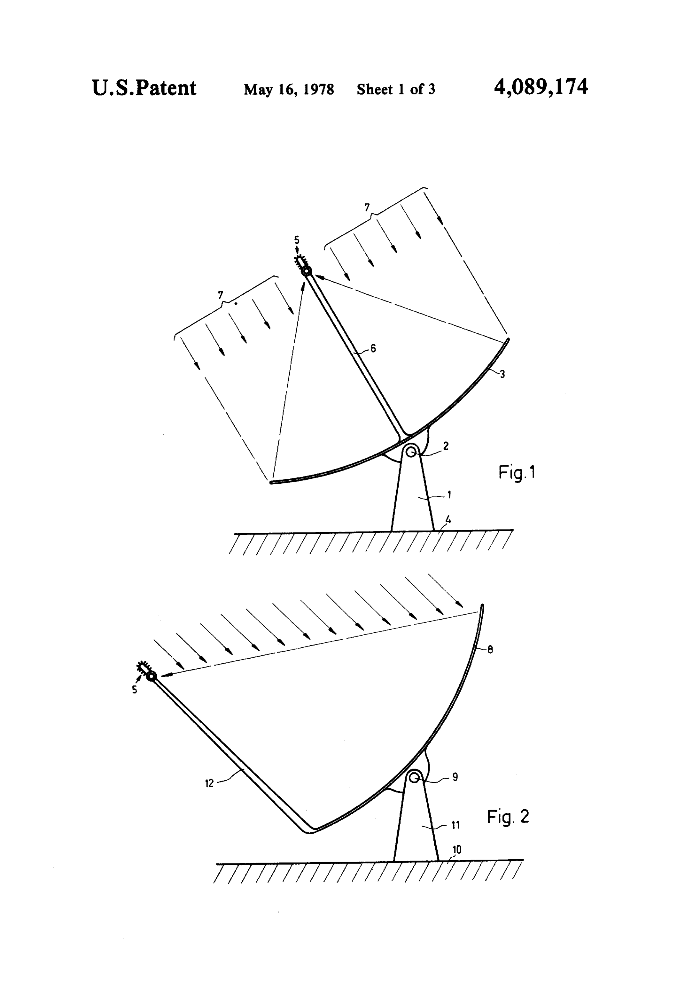
FIG, 2 is a side elevation of another embodiment of
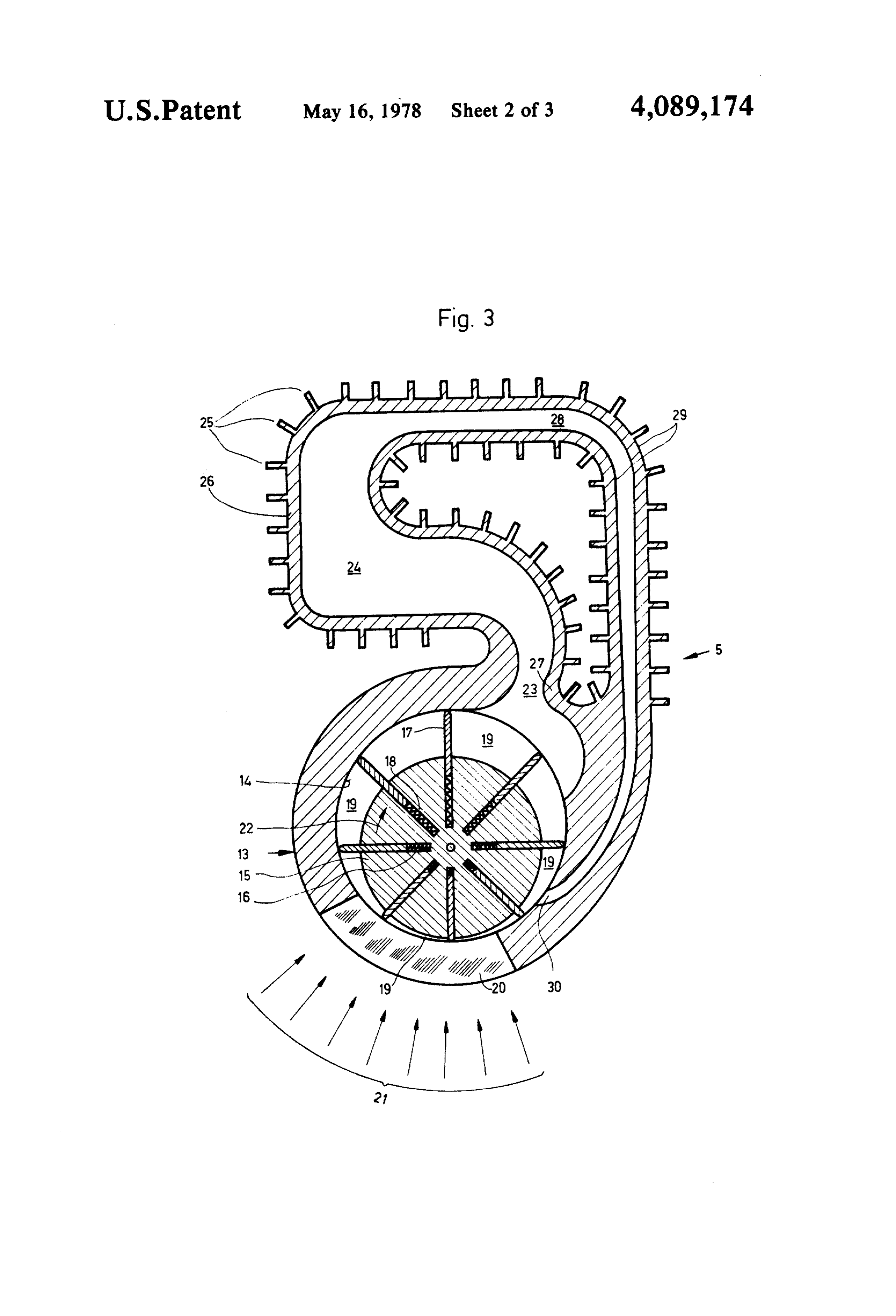
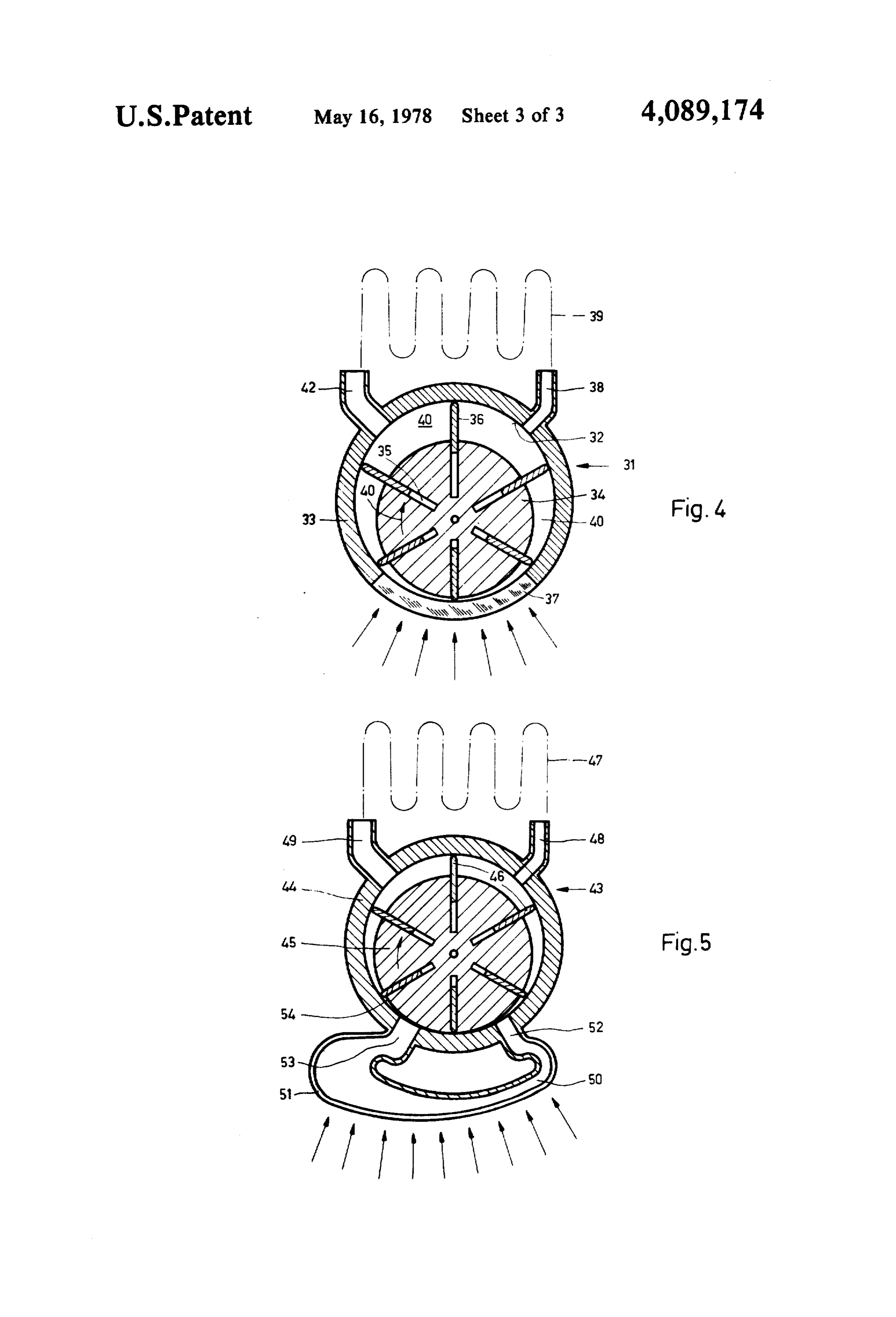
METHOD AND APPARATUS FOR CONVERTNG the apparatus having a halved parabolic reflector, RADIANT SOLAR ENERGY INTO MECHANCAL FIG. 3 is a cross-section through a heat engine as ENERGY used in the apparatus shown in FIGS. 1 and 2, 5 FIG. 4 is a cross-section through part of a second
This invention relates to a method of converting solar design of the heat engine, and energy into mechanical energy by concentrating radiant FIG. 5 is a cross-section through part of a third de solar energy in an operative zone by means of a reflec sign of the heat engine.
tor, and to an apparatus for carrying out this method, The invention described below aims at keeping the comprising a reflector for concentrating radiant solar O solar energy in its high-yield form to the greatest extent energy in an operative zone and a heat engine having a possible, i.e., at introducing it at the highest possible closed cycle for a heat-transfer medium. temperature into a thermodynamic cycle for producing Various methods and apparatus have already been mechanical energy.
proposed for utilizing solar energy. Only temperatures The apparatus illustrated in FIG. 1 comprises a para up to certain limits, or even relatively low temperatures, 15 bolic cylindrical reflector 3 pivoted about a shaft 2 on a can be attained with the known manner of supplying support 1 firmly secured in the ground 4. The reflector heat to the heat-transfer medium, which means that the 3 can be caused to follow up the position of the sun by solar energy is not being utilized very efficiently. This drive means (not shown). A heat engine 5, which will be manifests itself in a low Carnot factor of the particular described in greater detail below with reference to FIG. heat-engine generating station. For example, the solar 3, is disposed along the focal line of the reflector 3. The energy is collected by means of collectors in which heat engine 5 is rigidly connected to the side edges of black-painted pipes are disposed. These pipes lead into a the reflector 3 by two carrier arms 6, only one of which central collecting pipe, through which water heated up 3isparallelvisible in FIG. 1. The sunrays 7 striking the reflector to 70° C. is supplied to a thermal power process. As a 25 tor 3 on antooperative one another are concentrated by the reflec zone, where the energy is directly result of the small difference in temperature between transmitted to a heat-transfer medium. the cold medium and the heated medium, the efficiency is very low. In most cases, although it is theoretically tus,FIG. 2 shows another embodiment of such an appara comprising a halved parabolic cylindrical reflector something under 10%, it is actually only about 2% in 8 which is pivoted mounted about a shaft 9 on a support practice. 30 11 secured to the ground 10. The heat engine 5, which The sun represents a very great energy potential which, unlike fossil fuels, is available unrestrictedly and may be the same as that in FIG. 1, is rigidly connected free of charge. Although solar radiation produces a carrier lower to the corner areas of the reflector 8 by two arms 12 and is disposed along the focal line of relatively low maximum energy density of 1 kwasq.m. the reflector 8 in such a way that the incident parallel on the earth's surface, it is a very high-yield form of 35 sunrays are concentrated energy from a thermodynamic point of view, for it The advantage of using theinhalved the area of the heat engine. parabolic cylindrical issues from a heat source of over 6000 C. The greatest reflector 8 is that the heat engine 5 is then situated out proportion of energy occurs in the form of electromag side the region through which the sunrays pass to strike netic radiation in the shorter-wave infrared frequency the reflector 8, so that neither the heat engine 5 nor any spectrum. auxiliary devices impair the incidence of the sunrays on It is the object of this invention to provide a method the reflector 8. Furthermore, a more favorable distribu of converting radiant solar energy into mechanical en tion of energy density in the operative zone may be ergy, and an apparatus for carrying out that method, achieved thereby.
wherein the heat-transfer medium is brought to a higher FIG. 3 shows a cross-section through the heat engine temperature so that the conversion process may be 45 5. It may, for example, have a tubular housing 13 with carried out with substantially greater efficiency than a cylindrical bore 14 in which a rotor 15 is eccentrically has hitherto been possible with the known methods and mounted for rotation. The rotor 15 has a number of apparatus. grooves 16 extending radially throughout its length. To this end, in the method according to the present Positioned in each groove 16 is a radially movable slide invention, a heat-transfer medium contained in a closed SO 17. Between the bottoms of the grooves 16 and the cycle of a heat engine is conveyed through the opera slides 17 inserted therein are relatively weak spring tive zone, where it is directly insolated by the radiant members 18 which press the slides 17 outward so that solar energy, which is thereupon absorbed by the heat when the rotor 15 is at a standstill, the slides 17 rest transfer medium. against the wall of the bore 14. When the rotor 15 is in The apparatus for carrying out the foregoing method 55 motion, the slides 17 are also pushed outward by cen further comprises a heating chamber for heating the trifugal force to achieve the necessary sealing effect heat-transfer medium, this chamber forming part of the between the slides 17 and the wall of the bore 14. A closed cycle, being disposed in the operative zone, and number of chambers 19 are each defined by two adjoin being enclosed by at least one wall, and at least a por ing slides 17, a portion of the wall of the bore 14, and a tion of such a wall is made of a material transparent to portion of the surface of the rotor 15. The volume of the radiant solar energy. chambers 19 is dependent upon the angle of rotation of Several possible embodiments of the invention will the rotor 15.
now be described in detail with reference to the accom The housing 13 comprises at the bottom, as viewed in panying drawings, in which: FIG. 3, a portion 20 made of a material which is perme FIG. 1 is a side elevation of an apparatus, shown 65 able to electro-magnetic radiation in the wave range of diagrammatically, for converting solar energy into me from 0.2 to at least 3.0 microns. The chambers 19 which chanical energy, having a parabolic reflector adapted to is lowermost, as viewed in FIG. 3, contains a liquid follow up the position of the sun, heat-transfer medium which is directly insolated 6 through the transparent portion 20 of the housing 13 by means (not shown) ensure that all slides 36 rest against part of the concentrated sunrays 21, which are there the inside of the housing 33 even when the rotor 34 is at upon for the most part absorbed by the heat-transfer a standstill. A lower portion 37 of the housing 33 illus medium. trated in FIG. 4 is made of a material permeable to By means of the very intensive effect of the radiation, electromagnetic rays in the wave-length range of from the heat-transfer medium in the lowermost chamber is 0.2 to at least 3.0 microns. very quickly heated and evaporated, the vapor prefera From a cooling device indicated only by a dot-dash bly even being super-heated. The pressure thereby pro line 39, cool gas or a gas mixture is conveyed through duced in the lowermost chamber 19 drives the rotor 15 an inlet channel 38 into a chamber 40 situated in the clockwise as indicated by an arrow 22. When the rotor 10 vicinity of the inlet channel 36. Upon rotation of the 15hs rotated approximately 180, the chamber 19 which rotor 34 in the direction indicated by an arrow 41, the was originally lowermost has reached its uppermost gas or gas mixture is compressed and conveyed into the position, and the expanded vaporous medium escapes operative zone on the inside of the transparent portion through a channel 23 into a cooling chamber 24 sur 37 of the housing 33.
rounded by a wall 26 provided with cooling fins 25. A 15 When the compressed gaseous medium enclosed protrusion 27 extends into the channel 23 so that most of within the chamber 40 reaches the operative zone, it is the vaporous medium flowing out of the uppermost quickly heated by the very highly concentrated radia chamber 19 reaches the coolig chamber 24 via the chan tion; and through the increase in pressure within the nel 23. Due to its further expansion and to the cooling chamber 40 caused thereby, the rotor 34 is driven, so effect on the wall 26 provided with the cooling fins 25, 20 that the heated medium leaves the operative zone, ex the vaporous medium flowing out of the uppermost pands for the most part, finally leaves the housing 33 chamber 19 cools down and condenses on walls 29 through an outlet channel 42, and is returned to the forming the inside of an outlet channel 28. The con cooling device indicated by the line 39. This cooling densed medium flows down along the narrowing outlet device may be a simple heat exchanger in which the channel 28 and is returned via a supply channel 30 to the 25 medium is expanded to such an extent that an adequate chamber 19 immediately preceding the lowermost exchange of gas takes place. Suitable heat-transfer chamber. The operation described above then begins media are gases, gas mixtures, suspensions, aerosols, or W. mists. The suspension or mist may contain particles It will be noted that this mode of operation bears a having lubricating properties. According to the me certain similarity to that of a rotary piston engine. The 30 dium used, the operating conditions will preferably be decisive difference is that the energy in the operative such that at least in the operative zone, the medium is in space, i.e., in the chamber 19 gradually expanding in the its hypercritical state.
direction of rotation of the rotor 15, is not produced by FIG. 5 shows a cross-section through a heat engine the combustion of a fuel but is transmitted to the heat 43 in still another embodiment. Eccentrically mounted transfer medium by direct insolation of thermal energy. 35 in a tubular housing 44 is a rotor 45 having radially The temperature to which the medium is heated by movable slides 46. The housing 44 comprises an inlet concentrated insolation may be so chosen as to be ap channel 48, connected to a cooling device indicated proximately as high as that of the gases in a combustion only by a dot-dash line 47, for supplying a heat-transfer engine. Thus a high Carnot factor, or rate of energy medium, and an outlet channel 49 which is likewise utilization, may be attained. connected to the aforementioned cooling device. Un As a result of the direct insolation of the heat-transfer like the embodiments illustrated in FIGS. 3 and 4, the medium through the transparent portion 20 of the hous slide 46 which happens to be in the lowermost position ing 13 by sharply focused solar energy, with absorption at any given time is pushed virtually completely into its of the energy by the heat-transfer medium, substantially groove in the rotor 45 because the rotor 45 is off-cen lower heat-transfer losses occur than is the case with 45 tered to such an extent that it almost touches the inside conventional methods in which the radiation is first of the housing 44 at the botton. directed to a black body containing a medium that is Disposed below the housing 44 is a heating chamber heated indirectly via conduction and convection. The 50 of which at least the lower wall 51, exposed to the present method also makes it possible to achieve a very concentrated radiation, is made of a material permeable high energy density for the transfer to the medium. 50 to electromagnetic radiaton. The relatively cool heat When energy is radiated directly into the medium, the transfer medium entering the housing 44 through the temperature of the latter is higher than that of the parts inlet channel 48 is compressed and forced into the heat surrounding it, whereby the thermal radiation of those ing chamber 50 through a supply channel 52. The me parts is also less, which likewise contributes to increased dium in the heating chamber 50 absorbs the concentrat efficiency. 55 edly insolated energy, is thereupon very quickly heated, The cooling effect in the cooling chamber 24 may be and is conveyed through an exhaust channel 53 into a increased by blowing a stream of cold air against the chamber 54 situated in the lowest part of the housing 44. cooling fins 25 or by providing a water-cooling system The excess pressure produced in the chamber 54 and the (not shown). The cooling-water heated in this way may respective arrangement of the channels 52 and 53 serve be further utilized for heating rooms or for operating to drive the rotor 45 and thus to return the heated and heat pumps. subsequently partially expanded medium via the outlet FIG. 4 shows a cross-section through a heat engine channel 49 to the cooling device indicated by the line 31 in a further embodiment which is suitable for opera 47.
tion with a gaseous heat-tranfer medium. A rotor 34 is A shaft (not shown) rigidly connected to the rotor 15, eccentrically mounted for rotation in a bore 32 of a 65 34, or 45 passes through one of the end faces of the tubular housing 33. The rotor 34 has six radially housing of the heat engine 5, 31, or 43 described above. directed longitudinal grooves 35, in each of which a Any kind of machine can be driven by means of a wheel slide 36 is movably positioned. Relatively weak spring or gears mounted on that shaft. Preferably, the shaft is 7 connected to an electric generator for generating elec energy active chamber with said transparent hous trical energy. ing area;
It would also be possible to make the entire tubular e. inlet means for continuous introduction of the fluid housing 33 of the heat engine31 according to FIG. 4 of in said chamber including said transparent area; a material permeable to electromagnetic rays, e.g., 5 and quartz glass. In that case, however, those parts of the f. exhaust means for removal of that portion of the housing which are not exposed to radiation should pref fluid which has been expanded in said chamber erably be covered with a non-radiation-permeable coat having said transparent area with said exhaust ing, or else be made of a different material. means interconnected with said inlet means to pro It is not absolutely necessary for the heat engine to 10 vide a closed system; said system allowing for con extend over the entire length of the parabolic cylindri tinuous output of mechanical energy without pro cal reflector 3 or 8; instead, a number of such heat en vision of an energy storage means as long as solar energy is provided to activate the system.
gines may be disposed in a row along the focal line of 2. The apparatus of claim 1 in which the vanes are the reflector. 15 eccentrically mounted so that the energy active cham Instead of the heat engine shown in FIG. 4, a rotary ber has the smallest volume of any of the chambers. piston engine may be used. A heat engine operating in 3. The apparatus of claim 1 in which a rotor is in the manner of a hot-air turbine may likewise enter into cluded and into which the side walls are inserted and consideration. radially outwardly biased. Depending upon the particular embodiment, a circu 4. An apparatus according to claim 1, further con lar parabolic reflector will be preferred to the parabolic prising a cooling device disposed on a side of said heat cylindrical reflector for concentrating the radiation. engine remote from said operative zone. For example, only a circular parabolic reflector will be 5. An apparatus according to claim 1, wherein said used for a closed cycle with a two-stroke compression heat-transfer medium is a gas mixture capable of absorb piston engine. 25 ing radiation.
Owing to the direct transmission of solar energy to 6. An apparatus according to claim 1, wherein said the heat-transfer medium, which forms the basis for the heat-transfer medium is a suspension or an aerosol con invention described above, operation at the highest taining particles having lubricating properties. temperatures, limited only by the materials used, be 7. In a method for converting solar energy into me comes possible in that the solar radiation is sharply chanical energy, including means for collecting and focused and supplied through the radiation-permeable concentrating solar radiation and for converting solar wall directly to the medium for absorption thereby, this energy fluid, into mechanical energy by movement of a heating process taking place in the heating chamber of heated continuous the improvement comprising: producing heating and expansion cycles without stor a heat engine. 35 ing any of said energy as long as radiant energy is pres What is claimed is:
1. Apparatus for converting solar energy into me ent a by directly exposing a fluid to solar energy in one of series of chambers formed by a plurality of axially chanical energy comprising: rotatably mounted side walls and a housing surrounding a, a reflector means for concentrating radiant solar said side walls, said one of said chambers including a energy in a predefined area; 40 transparent wall formed in said housing expanding said b. a device for directly converting said solar energy fluid by said solar radiation through said chamber; into mechanical energy by means of a closed cycle forming an energy operative zone; rotating said side expansion of a fluid heated by direct radiation from walls due to expansion pressure and continuously re solar energy, said device including, peating the fluid expansion as other pairs of side walls c. a housing having a portion of its area transparent to 45 carrying the fluid are aligned with the transparent solar energy, said portion located in said prede chamber portion.
fined solar energy concentration area; 8. A method according to claim 7, wherein said me d. a series of axially mounted rotatable reciprocally dium is supplied to said zone in a liquid state and is movable side walls forming a plurality of chambers evaporated in said zone.
with said housing; two of said walls forming an SO
Provenance
- Collection
- Patents citing this work
- Pages
- 7
- Method
- pdftotext (the PDF's own text layer) + pdftoppm 300dpi page scans
- Patent office record
- patents.google.com →
- Source
- Google Patents citing-documents table
- Assignee
- Mario Posnansky
- Published
- 1978-05-16
- Transcribed from
- patentimages.storage.googleapis.com →