

patent · US4089629A
Process and apparatus for controlled recycling of combustion gases
16 May 1978
Text
Page 1bibliographic recordscan →
United States Patent (19)
Baumgartner et al.
54 PROCESS AND APPARATUS FOR
CONTROLLED RECYCLING OF
COMBUSTONGASES.
75 Inventors: Henri Baumgartner, Bernex; André
Jacquemet, Grand-Lancy, both of
Switzerland; John George Meier, San
Diego, Calif.; Bernard Vollerin,
Geneva, Switzerland 73 Assignee: Pietro Fascione, Busto Arsizio
(Varese), Italy
(30. Foreign Application Priority Data
Feb. 12, 1975 Switzerland ......................... 1706/75 Dec. 15, 1975 Switzerland ....................... 16208/75 51 Int. Cl’............................................... F23M 3/00 52 U.S. C. ......................................... 431/9; 431/116
2,058,089 10/1936 Lundborg et al........................ 431/8 2,180,190 11/1939 Baro ................................. 431/159 X 2,721,735 10/1955 Permann .......................... 431/116X 3,021,892 2/1962 Brola .................................... 431/116 3,042,105 7/1962 Bitterlich ......................... 431/181 X 3,097,686 7/1963 Morrow ........................... 431/15 X 3,402,985 9/1968 Galvin ..... . 431/116 3,604,824 9/1971 Hardison. . 431/16 3,741,166 6/1973 Bailey ...................................... 43/9
3,781,162. 12/1973 Rudd et al. .......................... 431/115
3,868,211 2/1975 Haye et al. ...................... 431/115 X Primary Examiner-Edward G. Favors
Assistant Examiner-Larry Jones
Attorney, Agent, or Firm-Karl F. Ross
Formation of nitrogen oxides and/or soot is obviated by mixing recycled combustion gas with incoming combu rant supplied to a burner via a distribution opening and controlling the mass flow rate of combustion gas being recycled with respect to the mass flow rate necessary for the gaseous comburant, the mixture being passed to the burner as a turbulent flow in which the ratio be tween the kinetic momentum flux of the mixture and the product of the radius of the said distribution opening times the axial movement quantity flux of the mixture has a value at least sufficient so that the said turbulent flow produces a recirculation of the said mixture within the combustion chamber in the form of a toroidal vor tex. This is achieved by apparatus comprising a mixing enclosure having two inlets each provided with means for regulating the size of its aperture, and an outlet, inlets communicating respectively with the atmosphere and with a duct for combustion gases, the outlet being connected to the inlet of a ventiator whose outlet com municates with gas mixture supply means arranged coaxially to a fuel injection nozzle in order to impart a turbulent motion to the gas mixture emitted from the supply means.
7 Claims, 7 Drawing Figures
strass sa\s
Drawings

Page 2drawing sheetscan →
Page 3drawing sheetscan →
Page 4drawing sheetscan →
Page 5drawing sheetscan →
Page 6drawing sheetscan →
Page 7drawing sheetscan →
Page 8scan →
Furthermore, the laboratory prototype described does
PROCESS AND APPARATUS FOR CONTROLLED not appear to be easily applicable to industrial use. RECYCLING OF COMBUSTONGASES The work which has been mentioned would seem to
FIELD OF THE INVENTION prove that it should be possible to perform combustion 5 with a low rate of formation of NO while approaching
This invention relates to a method of controlling the conditions of stoichiometric combustion, by virtue of combustion of a fluid fuel and to apparatus for use in the recirculation of the combustion gases on the one that method. hand and the turbulent flow on the other hand. How
Background of the invention
ever, the solutions proposed do not in practice provide 10 the combustion stability and cleanliness which ought
The formation of nitrogen oxides (NO) in the case of theoretically to have been expected using recirculation most fuels, and of soot in the case of liquid fuels, are two techniques and turbulent flow. problems always associated with combustion chambers. The causes of this relative lack of success are doubt These problems tend to be accompanied by flame insta less many and varied. In the case of internal recircula bility. The production of soot which accompanies the 5 tion, the basic problem involves the delay in establish combustion of liquid fuels seem at first blush to be in ing a satisfactory combustion. The formation of a flow compatible with the formation of NO, since the former of combustion gas in the direction of the reduced pres results from a deficiency of oxygen supplied by the air. sure region in the air injection zone, upstream of the fuel In order to deal with the problem of NO much work injection nozzle, in fact takes a certain time to become has been carried out on the recirculation of combustion 2O established since the combustion gases in the combus gases. The object of this recirculation is to reduce the tion chamber are aspirated by the funnel on the one excess of the air necessary for combustion while in hand, and by the air injection zone on the other hand. Another reason for this partial lack of success is mani creasing the mass flow rate. The result of this is to pro fested in a fairly high degree of flame instability, which vide a better utilization of the oxygen without increas 25 is reflected ing the production of nitrogen oxides (NO), which are the noise produced in a fluctuating mode of combusion. Finally, a serious source of atmospheric pollution, and in general the turbulent type of by yellow-flame combustion or by to provide the so-called "blue flame” combustion. flow may exceed the normally Of the solutions which have been proposed, one permissible level.
The instability of the flame is due to a large extent to makes use of an air injection zone above or upstream of 3O a poor mixture of fuel and air and to insufficient dilution the fuel injection zone. This air injection zone is con of the available nected on the one hand to the fuel injection zone, and combustion, in particularoxygen. In order to obtain a satisfactory on the other hand to the combustion chamber. The air one with a blue flame, the fuel if liquid must be atomized into sufficiently fine droplets.
injected into the air injection zone causes a reduction in It pressure, which draws the combustion gases from the 35 cientlyis also necessary for the available oxygen to be suffi chamber towards this zone and reinjects them, together combustion diluted in the gaseous mass formed from air and with air, into the fuel injection zone. This solution has gas. In fact, in order for the air excess to be the disadvantage that a relatively long delay is neces reduced to a minimum and for the combustion thereby to approach stoichiometric conditions, it is necessary to sary to obtain a satisfactory combustion. This delay is ensure not tolerable, bearing in mind the frequent stopping and bility ofthat each molecule of oxygen has a good proba meeting a molecule of fuel. This is the reason starting operations particularly in the case of a boiler. why it is not sufficient to recirculate a certain amount of Other solutions have been proposed to improve the combustion gas: the oxygen must also be diluted in a combustion. One of these relates to the turbulent flow homogeneous manner throughout the mass of gas. of the air feeding the burners and is generally known by In order to achieve this dilution it is desirable to use the anglo-saxon expression "swirl'. One chapter in the 45 a gas whose partial pressure of oxygen is less than that work of J. M. Beer and N. A. Chigier, "Combustion
Aerodynamics', Applied Science Publishers Limited, of air, so as to exploit the greater part of the available oxygen, thereby leading to a reduction in the produc
London (1972) is devoted to this topic. This work tion of NO. However, the reinjection methods so far shows in particular that the turbulent flow of the air used have not ensured a sufficiently good dilution of the around the fuel injection cone increases both the stabil 5O oxygen. Consequently, since the mass of gas does not ity and luminosity of the flame, considerably alters the have a constant partial pressure of oxygen in the reac shape of the flame, which thus spreads very rapidly tion zone with respect to time, the combustion may not from the outlet of the fuel injection nozzle, and pro be uniform.
duces a high degree of mixing and turbulence. On the The stability of the flame cannot be guaranteed even other hand, this improvement in the flame does not lead 5 5 by combining turublent flow and recirculation, doubt to sootless combustion, and is accompanied by a high less for the same reason, namely an incomplete dilution level of noise due to the turbulence and the very high of the available oxygen in the mass of gas. combustion rate. This noise level may even exceed the permissible limits. OBJECT OF THE INVENTION Finally, there may also be mentioned an experiment 60 The object of the present invention is to obviate, at which has been carried out on a gas burner in order to least in part, the disadvantage of the afore-mentioned reduce the amount of NO. In accordance with the solutions so as to ensure a blue flame combustion which experiment, four pipes lead tangentially into a tubular is stable, produces a small quantity of NO, and gener chamber which is concentric with a gas inlet pipe. Air ates less noise.
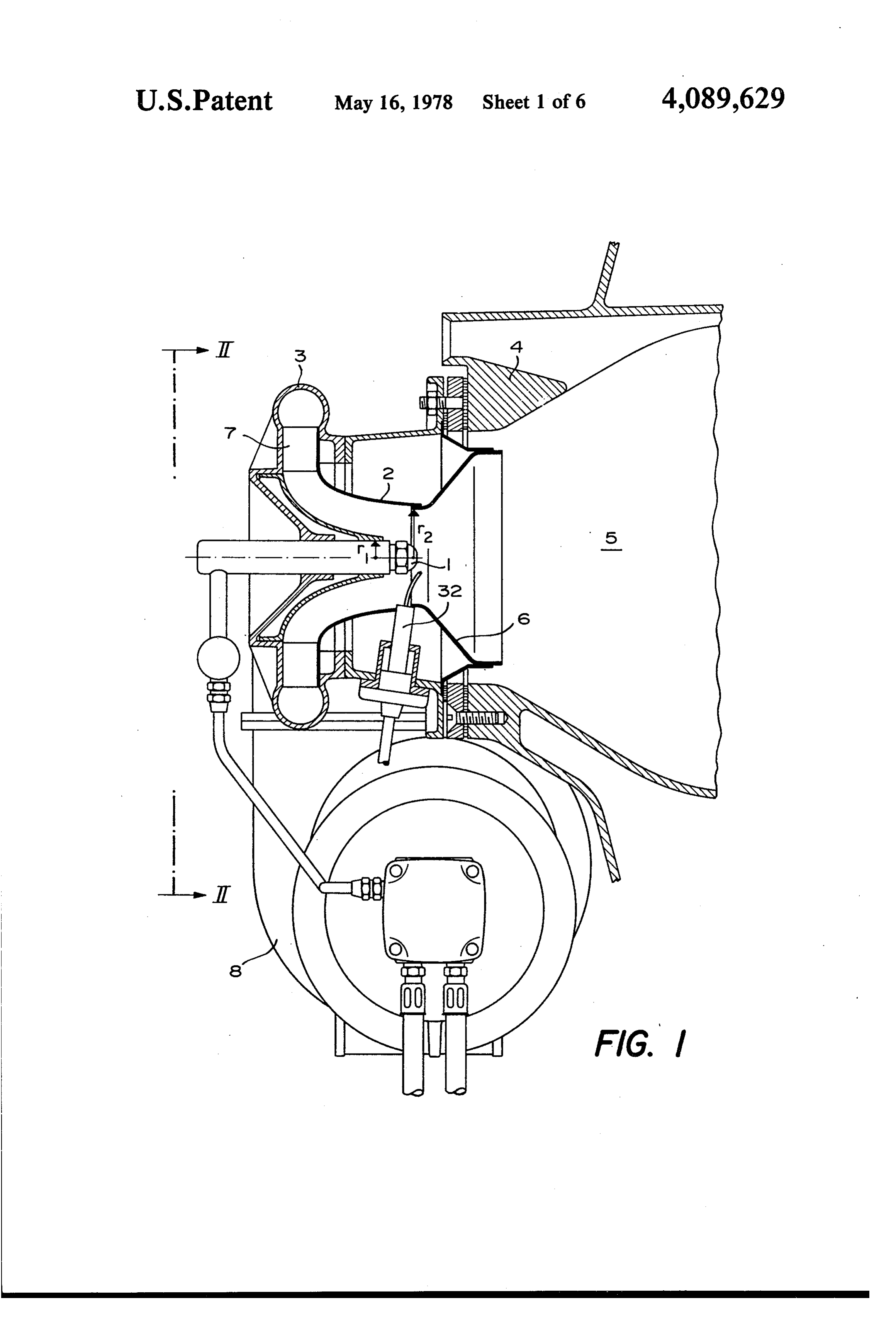
and combustion gases are passed under pressure so as to 65 form a "swirl' around the nozzle. However, these ex SUMMARY OF THE INVENTION periments have not gone beyond the laboratory stage To this end, one feature of the present invention com and appear to have come up against stability problems. prises a process for supplying a comburant to a fluid fuel 9 burner whose comburant distribution opening opens this combustion chamber in a pot 6, the role of which into a combustion chamber, comprising the combina will be explained hereinafter. A fixed blade member 7 tion of steps in which: forming a crown is arranged in the outlet of the spiral a zone of reduced pressure is formed upstream of the tank 3 and has a pitch or gradient intended to impart a burner; 5 helical movement to the gas mixture introduced into the this zone is connected to a source of gaseous combu combustion chamber 5.
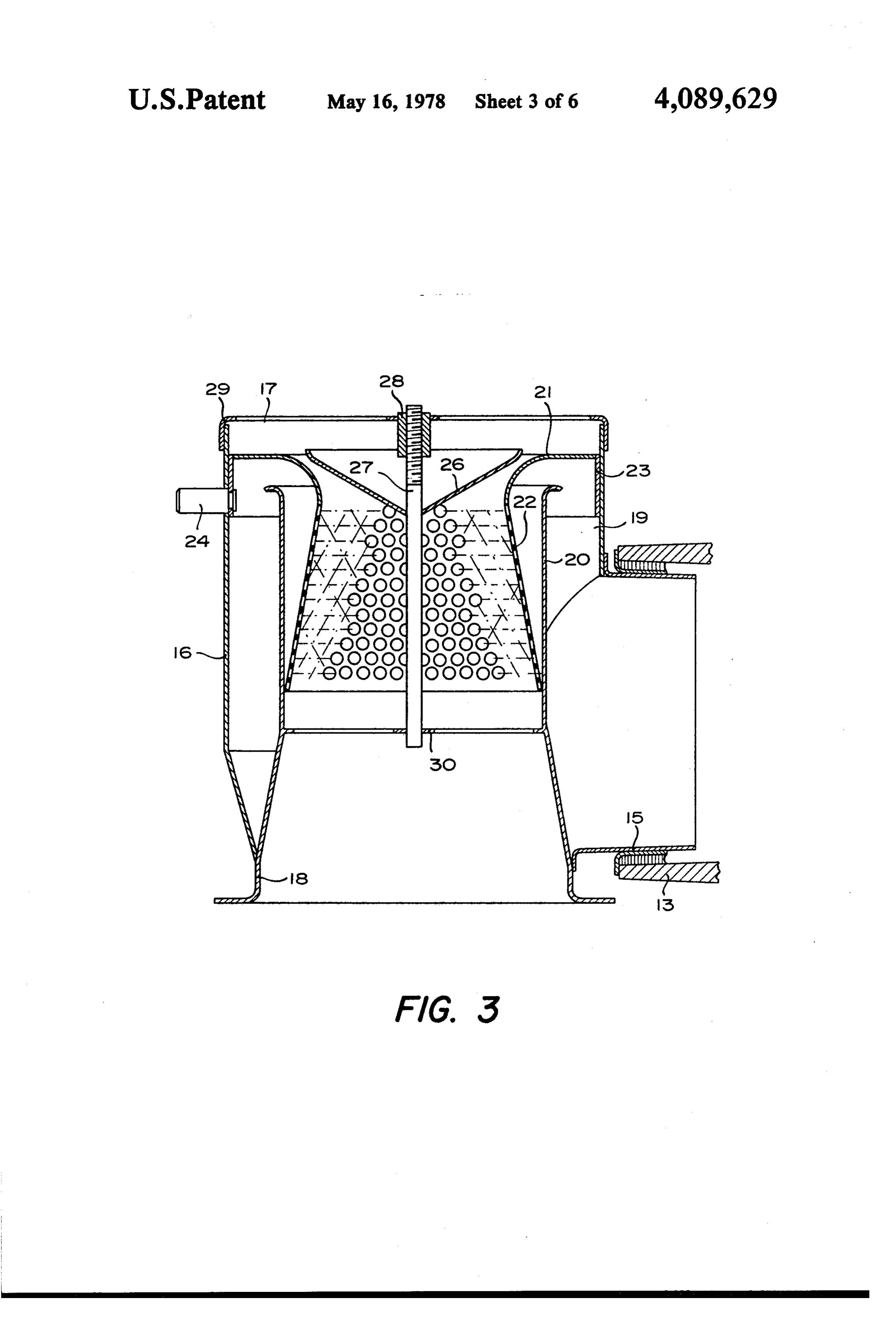
rant on the one hand, and to a pipe for removing the The inlet of this spiral tank 3 communicates with the combustion gases on the other hand; outlet of a second spiral tank 8, in which a fan-wheel 9 the mass flow rate of combustion is controlled with is mounted and is driven by a motor 10 via two helical respect to the necessary mass flow rate of gaseous com- 10 tooth gears 11 and 12 which are integral with, respec burant; tively, the shafts of the wheel 9 and the motor 10. the combustion gases are mixed with the gaseous The structure of the boiler, combined in this example comburant to reduce the oxygen concentration of the with the combustion chamber 5, will not be described in comburant mixture, and detail since it is outside the scope of the invention. In the mixture is introduced into the combustion cham- 15 order to understand the invention it is sufficient to know ber via the said distribution opening, while forming a that in this example the boiler has two collectors for turbulent flow in which the ratio between the kinetic combustion gas, one of which, 13, is in communication momentum flux of the mixture on the one hand, and the with a first inlet 15 (FIGS. 2 and 3) of a gas mixing product of the radius on the said distribution opening enclosure 16 (FIG. 3) whose second inlet 17 com times the axial movement quantity flux of the mixture 20 municatss with the atmosphere, while the outlet 18 on the other hand, has a value at least sufficient so that branches at the inlet of the second spiral tank 8 of the the said turbulent flow produces a recirculation of the ventilator, which is regulated by a flow regulation said mixture within the said chamber in the form of a sleeve 14 which can move axially. toroidal vortex. The first inlet 15 of the enclosure communicates with In a further feature of the invention, a part of the said 25 an annular zone 19 formed between the external tubular mixture is withdrawn upstream of the distribution open envelope of the enclosure 16 and an internal wall 20 ing of the burner and this part of the mixture is led to the located in the extension of the outlet 18. A regulating vicinity of the ejection orifice of the nozzle in order to annulus 21 carried a perforated collar 22 which widens prevent blockage of this orifice by products internally in the direction of the outlet 18 and rests against the recirculated by the sid toroidal vortex. 30 internal wall 20. This regulating annulus 21 is integral The basic advantage of this process and the apparatus with a cylindrical sleeve 23 slidably mounted in the for carrying out the said process is the formation of a interior of the tubular envelope of the enclosure 16. The double recirculation, one being external via the aspira sleeve 23 carries a projection 24 which juts out beyond tion of a certain mass of combustion gas and the mixing the enclosure 16, through a helical groove 25. The an thereof with gaseous comburant, the other being inter- 35 gular displacement of the sleeve 23 by means of the nal in the form of a toroidal vortex of the comburant projection 24 enables the axial position of the sleeve 23 mixture induced by the turbulent flow of this mixture. to be altered and the passage section between this sleeve BRIEF DESCRIPTION OF THE DRAWING and the adjacent end of the internal wall 20 to be regu lated. The perforated tubular wall 22 serves to divide
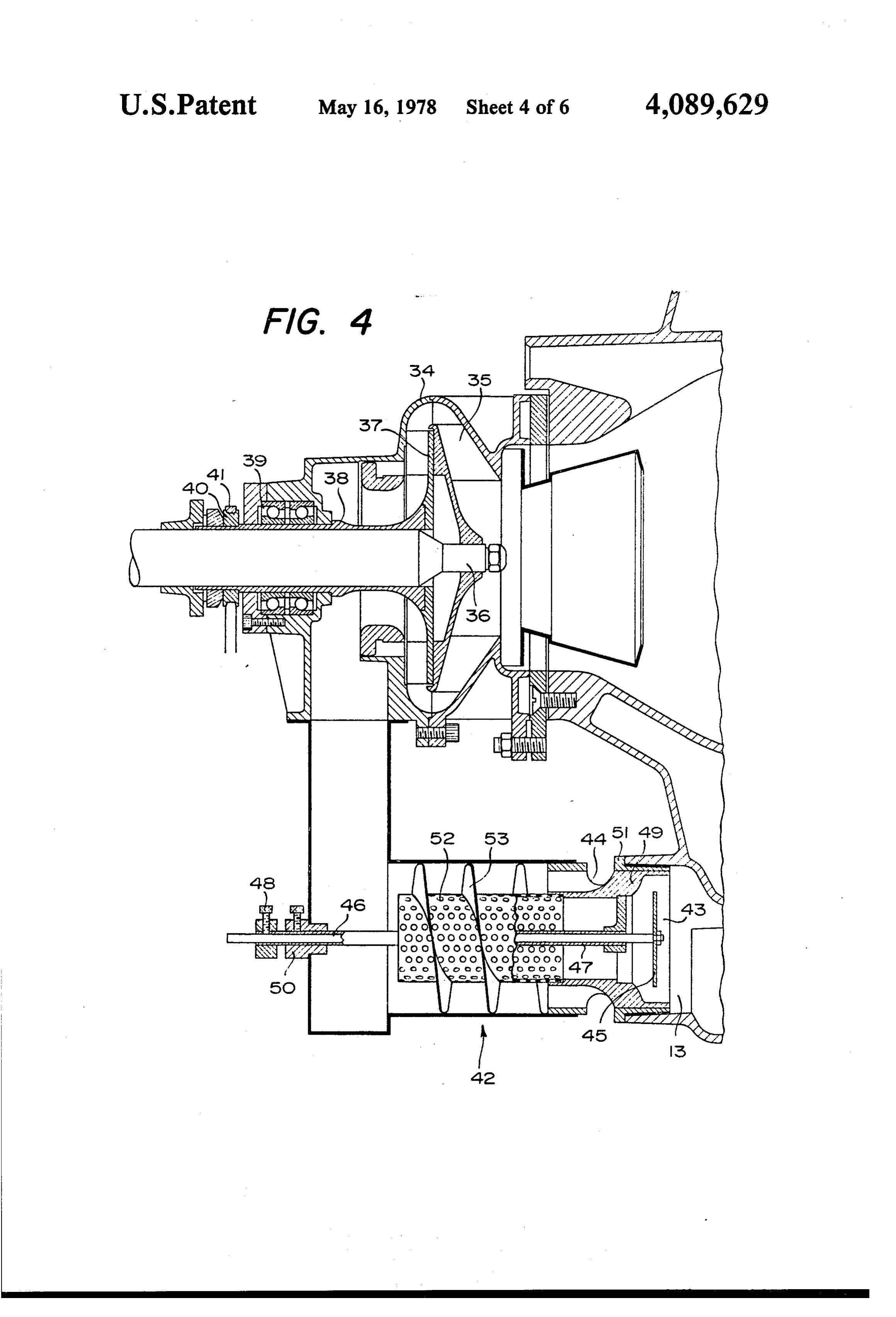
Other advantages will become apparent on reading 40 the flow of combustion gas coming from the collector the description illustrated by the accompanying draw 13, the purpose of which will be explained hereinafter. ing which represent, diagrammatically and by way of The second inlet 17 of the enclosure 16, which com example, two embodiments and one variant of the de municates with the atmosphere, is also provided with a vice for carrying out the present invention. device for regulating the aperture formed by a cone 26 In the drawing: 45 secured to a rod 27, a threaded end of which is screwed FIG. 1 is a sectional view along the longitudinal axis into a nut 28 integral with a perforated cover 29, and the of the combustion chamber. other end of which is guided in a perforated disc 30. FIG. 2 is a partially sectioned elevational view along This cone 26 together with the regulating annulus 21 the arrows II - II of FIG. 1. form an annular passage.
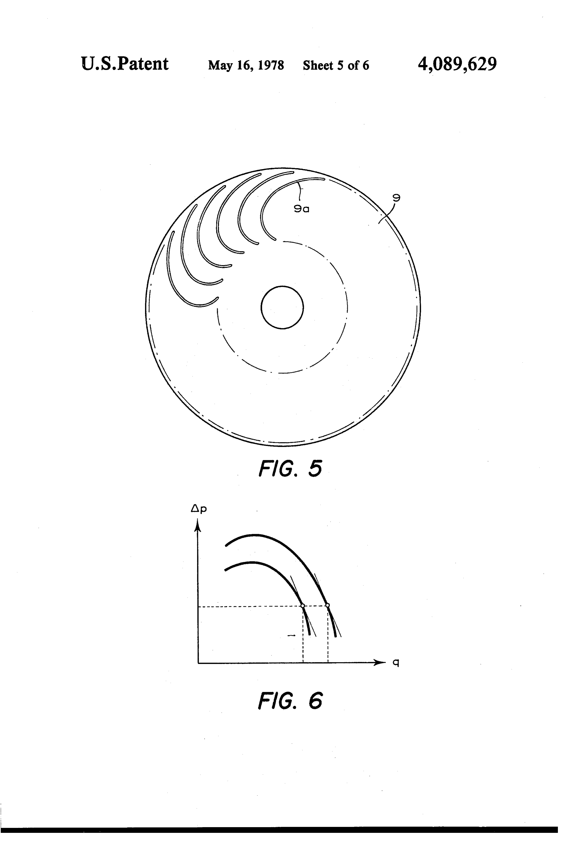
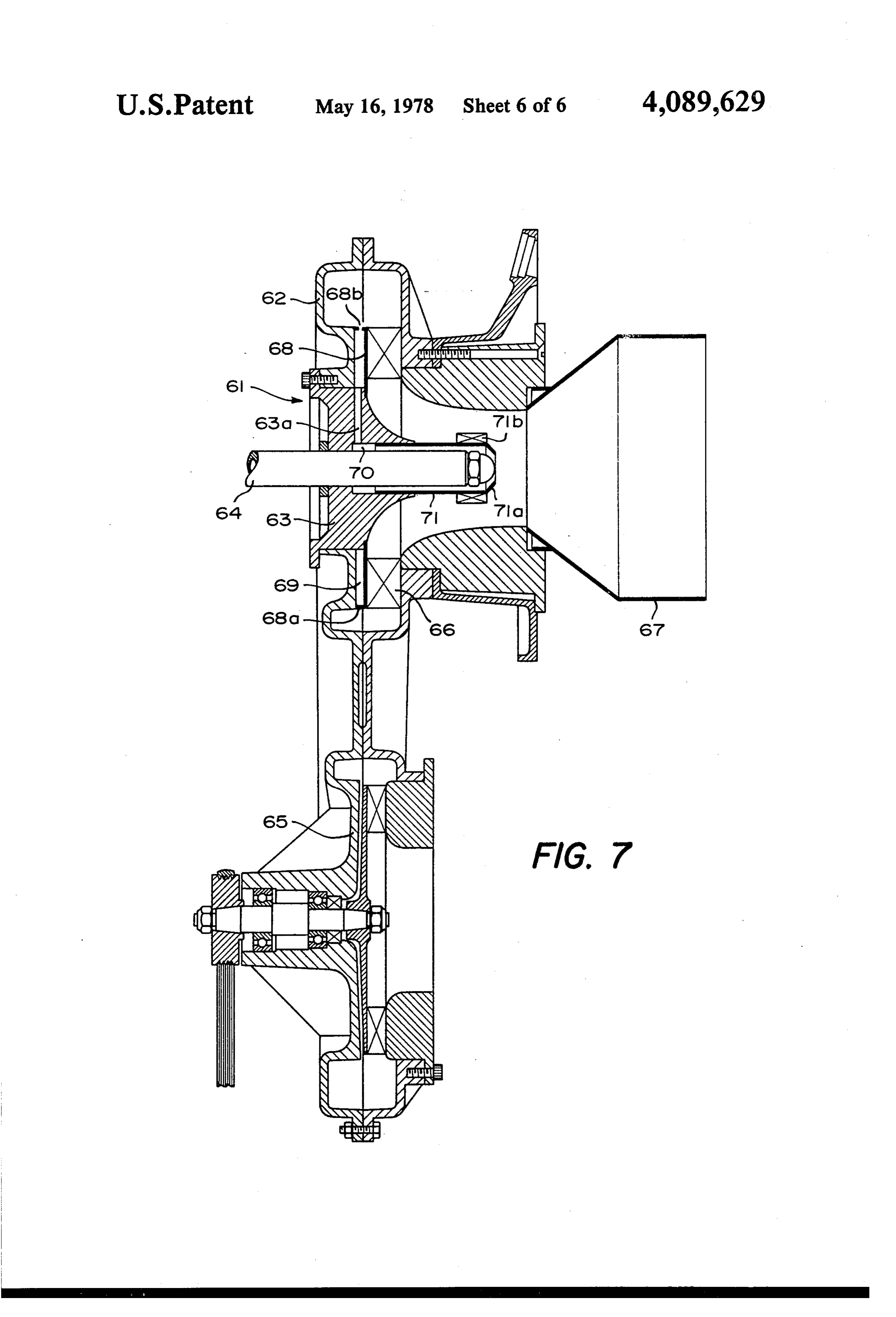
FIG. 3 is a detailed view, in section and on an en- 50 It may also be mentioned that the mazut injection larged scale, along the line III - III of FIG. 2. nozzle 1 is fed by a pump 31 and that an ignition elec FIG. 4 is a sectional view similar to that of FIG. 1, trode 32 is arranged near the nozzle 1. illustrating the second embodiment. When the boiler is operating, the combustion gases FIG. 5 is a part view of a detail of the ventilator. are collected in collectors (only collector 13 is visible) FIG. 6 is a diagram explaining the method of regulat- 55 situated at the outlet of convection pipes of the boiler ing the ventilator. (which are not shown), and along which these gases FIG. 7 is a sectional view along the longitudinal axis cool by transferring heat to the water of the boiler. In of the combustion chamber, of a variant of the first addition to the pressure reduction exerted by the draw embodiment. of the flue at which the collectors branch, a second 60 pressure reduction, more powerful than that of the flue,
Specific description
is created in the gas mixing enclosure 16 by the ventila
The apparatus for supplying a fluid fuel burner with tor. 8,9. Since this enclosure 16 communicates via its a mixture of air and combustion gas, shown in FIGS. 1 inlet 15 with the fume collector 13, the combustion and 2, is provided with a mazut (petroleum residue) gases are drawn into this enclosure 16 at the same time injection nozzle 1 arranged coaxially in a supply pipe 2 65 as the air which is drawn in through the inlet 17. The for providing a mixture of air and combustion gas. This total gas volume (air plus combustion gas) drawn into pipe 2 forms the outlet of a spiral tank 3 secured to the the enclosure 16 as well as the air/combustion gas ratio cover 4 of a combustion chamber 5, and terminates in are determined, by a flow rate previously fixed for the 10 ventilator 8,9, by regulating means consisting of the The axial quantity movement flux is given by the regulating annulus 21 and the cone 26. This latter ena formula:
bles the total volume of aspirated gas to be regulated, whereas the annulus 21 enables the proportion of air and r combustion gas admitted into the enclosure 16 to be 5 G = 27 if p Urdr + 2ar f Pr dr regulated. r r As has previously been said, the flow of combustion gas into the enclosure 16 via the first inlet 15 is divided in which P is the static pressure at a given point r. into a plurality of flows during its passage through the Of the other factors which contribute to the quality wall of the perforated collar 22. This plurality of flows O of the combustion, the pot 6 may be mentioned again. affects the air flow which also results from the pressure The pot 6 contributes to the fixing of the flame in the reduction caused by the ventilator 89. The formation of space and increases, by its divergent shape, the toroidal the plurality of flows very considerably increases the volume of the vortex formed within the turbulent flow air-combustion gas interface and promotes the intermix 15 while extending it, with the result that the atomized fuel ing and turbulence of this plurality of flows. A recombi gasparticles in this vortex pass through a larger combustion nation of two dense masses of gas which intermix only of aand air mixing zone, which increases the probability combination between the molecules of oxygen and very partially so that the resultant mass of gas has a heterogeneous oxygen concentration constituting an fuel. The pot also serves as a radiation screen between instability factor in the combustion, is thus avoided. On 20 the base of the flame and the cold wall of the boiler, maintaining a sufficient temperature at this point of the the contrary, the penetration of a plurality of combus flame to promote the gasification of the fuel and its tion gas flows into the airflow promotes the distribution good combustion. However, it may be noted that with of the oxygen throughout the whole mass of gas, so that the cover of the boiler 4 which is shown, the presence the partial pressure of oxygen in the gas mixture is ap of the pot is not absolutely preciably constant. This uniform distribution of the 25 gards arresting the flame andessential, especially as re increasing the volume of oxygen ensures a maximum utilization of the available the toroidal vortex.
oxygen and enables the amount of air to be reduced so Two special features of the ventilator 8.9 must also be as to approach the stoichiometric value. It is found that with equal masses of air and recirculated gases, the pointed out. As shown in FIG. 5, the shape of the blade 9a of the wheel 9 of the ventilator is chosen so as to stability of the combustion improves considerably in 30 produce an acceleration of the fluid in proportion as the proportion to the homogeneity of the gas mixture. latter advances radially towards the spiral tank 8, so This mixture, formed in the enclosure 16, is aspirated that on ignition of the boiler the particles of soot which by the ventilator 89 which compresses it and passes it may be recirculated with the combustion gases are to the spiral tank 3, from which it passes into the feed swept from the surface of the blades 9a and do not pipe 2 after having passed via the fixed blade member 7 35 accumulate thereon.
which imparts to it a helical movement around the axis The other special feature, known per se, results from of the burner. This turbulent flow ("swirl”) reaches the the flow rate regulating system, regulation being ef. pot 6 in which the fuel is atomized by the nozzle 1. fected by the sleeve 14 projecting into the wheel 9, and In order to avoid pulsations in the flow of fresh air, not by throttling or constriction. The effect of the pene which would set up a pulsation phenomenon in the tration by this sleeve is to alter the characteristics of the whole of the boiler, the pressure created in the enclo ventilator, that is to say the curve of pressure variation sure 16 by the ventilator 8.9 is less than -10 mm water Ap as a function of the flow rateg. However, the stabil column. The "swirl” number, (G/r,G), which is given ity of the ventilator and thus the stability of the flame is by the ratio between the kinetic momentum flux G a function of the slope of the tangent to this curve. The imparted to the gas and the product of the radius of the 45 greater the slope the better the stability. By varying the distribution opening of the burner r (FIG. 1) times the flow rate by means of the annulus 14, the result is that axial quantity movement flux G is preferably chosen the flow operates with another ventilator wheel whose to be between 0.2 and 1.2. Ap/q characteristics are substantially parallel (FIG. 6) The lower limit should be at least sufficient to cause so that for the same p, the slope of the tangent is virtu a recirculation of the mixture in the interior of the tur 50 ally constant. This is clearly very important for the bulent flow, in the form of a toroidal vortex, while the stability of the combustion and constitutes an original upper limit is determined by the extent of the strike back method of regulating the mass flow rate of comburant of the flame under the effect of this toroidal vortex, fed to the burner.
which should not reach the nozzle 1. Tests carried out using the device described enabled As a reminder, and according to "Combustion Aero 55 an almost instantaneous, stable, blue flame combustion dynamics' mentioned previously, the kinetic momen to be obtained by employing a very slight excess of air tum flux G is given by the formula: with respect to stoichiometric conditions, of the order of only 5% to 10%, leading on the one hand to a practi cally sootless combustion, and on the other hand to a very low production of NO. Finally, the recirculation of combustion gas enables the noise level generated by the combustion to be lowered. Compared with the air in which U is the axial velocity, W is the tangential mass, this recirculation is between 50% and 70% of velocity at a given point r, rand rare the internal and combustion gas for a mass ratio of air and fuel close to external radii of the annular space constituting the dis 65 soichiometric conditions.
tribution opening of the mixture, r being the radius of As a comparison, recirculation of just combustion gas the nozzle and r2 that of the neck of the burner, and p is representing 50% in comparison with the mass flow the density. rate of the air leads to an excess of air of about 30%.
Page 11scan →
"Swirl" without recirculation produces an excess of air The nozzle carrier 63 has radial passages 63a for of about 50%. communication with an annular space 70 formed The second embodiment illustrated in FIG. 4 differs around the nozzle 64 by a disengagement effected in the from the first embodiment mainly in that the ventilator nozzle carrier 63 on the one hand, and by a collar 71 and turbulence generator are mounted in the same tank 5 which extends the nozzle carrier 63 in the direction of 34 which contains on the one hand a fixed blade 35 the combustion chamber on the other hand. This collar situated in the outlet of the tank and secured to the 71 terminates in an annular deflector 71a in the shape of nozzle holder 36, and on the other hand a fan 37 coaxial a truncated cone, the vertex of which is located in the with the fixed blade 35 and secured to a collar 38, con flame pot 67. However, the presence of this deflector is nected to a drive motor (not shown) by a transmission O optional, and tests have shown that good results can be belt 41. This tank 34 is supplied axially with a gas mix obtained with a simple cylindrical collar. ture by the pressure reduction created by the ventilator Radial vanes 71b project from the external surface of 37, via the connection between this tank 34 and the the collar 71 at the end thereof adjacent to the deflector mixing device 42, which differs slightly from the device 15 71a. These vanes extend only over a portion of the previously described. section of the distribution opening of the tank 62. This device comprises a first inlet opening 43 con When the ventilator 65 supplies the spiral tank 62 nected to the combustion gas collector 13, and second with air or a mixture of air and combustion gas or with inlet openings 44 which communicate with the atmo any other suitable gaseous comburant, the greater part sphere. The passage section of the opening 43 is regu 20 of this comburant passes across the fixed blade 66 which lated by a disc 45 which can move axially and is creates the swirl flow around the nozzle 64. The central mounted to this end on a rod 46 guided by a tube 47. A part of this comburant flow meets the vanes 71b, which regulating screw 48 serves to fix the axial position of have the effect of breaking up the swirl of this central this rod 46 in the tube 47. This tube is integral with a part, corresponding to the place where the flow rate is collar 49 secured to one of its ends, while being slidably greatest. The result of breaking up the central part of mounted in a socket 50 at its other end, the socket itself 5 this flow is to lower the velocity thereof to the flamma bility limits of the fuel/comburant mixture. This step being integral with the enclosure containing the device allows 42. The collar 49 comprises two parts, one of large despite ignition to take place at the centre of the flow diameter in which is arranged the first opening 43, and "catches'theat intensity of the swirl, so that the flame the burner.
slidably mounted in a tubular element 51 controlling the 30 Some of the pressurized gaseous comburant flow is second opening 44, and the other of smaller diameter, to withdrawn which a perforated cylinder 52 surrounded by a helical way formedand by passes to the spiral tank 62 via the path the openings 68b, the radial passages 63a fin 53 is secured.
and the annular
The air sucked in by the pressure reduction created annular deflector 71a. Thatspace 70, which is terminated by the by the ventilator 37, and which passes into the mixing 35 gaseous comburant divertedportion of the pressurised device 42 via the openings 44, is subjected to a helical purpose of effecting an aeration of the pathway by this end of the has the nozzle motion imparted by the fin 53. At the same time the 64 in order to prevent unburnt particles of fuel or any combustion gases sucked in through the opening 43 are other particles entrained in the toroidal vortex pro split up by the perforations in the cylinder 52 and this plurality of jets penetrates the helical air flow and pro 40 duced by the swirl from being deposited on the surface of the nozzle 64 and thereby blocking it.
duces a homogeneous mixture. This mixture is then We claim:
compressed by the ventilator 37 and the fixed blades 35 1. A process for combusting a fuel in a burner having impart a turbulent flow thereto, under the same condi a nozzle for dispensing a combustible fluid, a combus tions as in the first embodiment. tion chamber downstream of said nozzle, and a distribu The head of the burner 61 of the variant shown in 45 tion opening upstream of said nozzle and communicat FIG. 7 comprises a spiral tank 62 which receives at its ing with said chamber around said nozzle, said method centre a nozzle carrier 63 through which passes axially comprising the steps of:
an opening, in which an atomizer nozzle 64 for fluid fuel (a) generating a zone of reduced pressure upstream of supplied from a pressurized source of fluid fuel (not said opening;
shown) can be adjusted. This spiral tank is connected to 50 (b) communicating said Zone simultaneously with a the outlet of a ventilator 65 which constitutes the source source of an oxygen-containing gaseous comburant of pressurized gaseous comburant. The spiral tank 62 is and with said chamber whereby said reduced pres provided with a swirl generator and has, for this pur sure in said zone draws said gaseous comburant and pose, a fixed blade 66 whose vanes are orientated as a recycled combustion gas from said chamber function of the intensity or number of swirls desired. 55 through a common duct;
This blade 66 controls access to the central distribution (c) mixing the stream of gaseous comburant with the opening of the tank 62, concentric with the nozzle 63. stream of recycled combustion gas in said duct by This distribution opening connects the spiral tank 62 subdividing one of said streams into a multiplicity to a flame pot or box 67 located at the inlet to the com of flows and dispersing said multiplicity of flows in bustion chamber, the boundaries of which are not the other of said stream, thereby producing a com shown in the drawing. burant mixture with an oxygen concentration sub The blade 66 is integral with a disc 68 secured to the stantially less than that of said gaseous comburant; nozzle carrier 63 whose circumference has a flange 68a (d) controlling the mass-flow rate of said mixture to which extends up to the face of the disc 68 opposite that substantially completely burn a combustible fluid carrying the blade 66. This flange 68a bears against the 65 supplied by said nozzle to said chamber; housing of the tank 62, forming an annular enclosure 69 (e) controlling the oxygen concentration in said mix which communicates with the remainder of the tank 62 ture to slightly exceed the stoichiometric require via openings 68b which pass through the flange 68a. ment of oxygen for combustion of said fluid;
Page 12scan →
(f) introducing said mixture into the combustion a blower in said outlet passage ahead of said opening chamber through said opening and imparting a for generating a reduced pressure in said mixing turbulent flow to the mixture introduced into said vessel, thereby inducing said gaseous comburant chamber through said opening in which the ratio and recirculated combustion gas into said vessel between the kinetic momentum flux of the mixture and for displacing the resulting mixture into said and the product of the radius of said distribution combustion chamber through said opening; opening times the axial movement quantity flux of perforated partition means in said vessel between said said mixture has a value at least sufficient to pro inlet passages for subdividing the fluid flow duce a recirculation of said mixture within said through one of said inlet passages into a multiplic chamber in a toroidal vortex, the latter recircula O ity of streams and mixing said streams with the tion being independent from the recirculation of flow through the other inlet passage to produce combustion gas from said chamber through said said mixture with a homogeneous distribution of duct; said gaseous comburant and said recirculated com (g) directing said combustible fluid from said nozzle bustion gas; and through said toroidal vortex whereby said fluid 15 turbulence-generating means at said opening for im mixes therewith; and parting to said mixture the configuration of a toroi (h) burning the mixture of said fluid and the gases of dal turbulent vortex downstream of said opening said toroidal vortex to produce said combustion and said nozzle and inducing a recirculation of gas gases in said chamber. from said chamber into said toroidal vortex inde 2. The process defined in claim 1 wherein said ratio is 20 pendently of the recirculation through said con between substantially 0.2:1 and 1.2:1. duit, said turbulence-generating means including 3. The process defined in claim 1, further comprising an array of vanes whose orientation in conjunction the step of feeding a portion of the mixture formed in with the radius of said opening creates said toroidal step (c) along said nozzle to prevent blockage thereof Votex.
by products recirculated in the toroidal vortex in step 25 5. The apparatus defined in claim 4 wherein a housing (f). provided with two opposite axial openings is mounted 4. An apparatus for feeding a gaseous comburant to a coaxial with said nozzle, the opening of the housing burner provided with a nozzle for injecting a combusti remote from the nozzle communicating with said ves ble fluid into a combustion chamber coaxial with an sel, said housing having an upstream end receiving said opening for distribution of said comburant, said com 30 blower and a downstream end provided with said bustion chamber having at least one conduit for with Wales, drawal of combustion gases, said apparatus comprising: 6. The apparatus defined in claim 4, further compris a mixing vessel provided with two inlet passages and ing means for feeding a portion of said mixture along an outlet passage, one of said inlet passages being said nozzle to prevent blocking thereof. connected to said conduit, said outlet passage being 35 7. The apparatus defined in claim 6 wherein the last connected to said opening and the other inlet pas mentioned means includes a sleeve formed with an an Sage being connected to a source of a gaseous com nular outlet around the discharge end of said nozzle, burant; said outlet being formed with an inwardly extending means for controlling the flow cross section of each deflector.
of said inlet passages independently of the other; 40
Provenance
- Collection
- Patents citing this work
- Pages
- 12
- Method
- pdftotext (the PDF's own text layer) + pdftoppm 300dpi page scans
- Patent office record
- patents.google.com →
- Source
- Google Patents citing-documents table
- Assignee
- Pietro Fascione
- Published
- 1978-05-16
- Transcribed from
- patentimages.storage.googleapis.com →