

patent · US4091800A
Solar pond
30 May 1978
Text
Page 1bibliographic recordscan →
United States Patent (19) 4,091,800 Fletcher et al. May 30, 1978 54 SOLAR POND 3,893,506 7/1975 Laing ................................... 126/27 3,918,430 1 1/1975 Stout et al............................ 126/271 (75) Inventors: James C. Fletcher, Administrator of Primary Examiner-John J. Camby the National Aeronautics and Space
Administration, with respect to an Assistant Examiner-Henry C. Yuen invention of Charles G. Miller, Attorney, Agent, or Firm-Monte F. Mott; John R.
Pasadena; James B. Stephens, La Manning; Wilfred Grifka
Crescenta, both of Calif. 57 ABSTRACT 73 Assignee: The United States of America as Use of shallow pools of liquid to collect low-tempera represented by the Administrator of ture solar generated thermal energy on a large scale for the National Aeronautics and Space commercial use becomes economically feasible when Administration, Washington, D.C. use is made of efficient means to keep the liquid in the 21 Appl. No.: 811,815 pond clean, prevent evaporation, prevent air convec 22 Filed: Jun, 30, 1977 tion and prevent convective circulation of the liquid. Narrow elongated trenches, grouped together over a
Related U.S. Application Data wide area, can be formed by bulldozer type equipment. Each trench is lined with a heat-absorbing black liner.
63 Continuation of Ser. No. 590,975, Jun. 27, 1975, The liquid in the bottom of each trench, used to absorb abandoned. the solar energy, may be a brine solution or plain water, Int. Cl’................................................. F24, 3/02 depending on the means used to remove the thermal 52 U.S. C. .................................... 126/271; 237/1 A energy from the pond. The heat-absorbing liquid is kept 58 Field of Search ....................... 126/270,271, 400; separate from the thermal energy removing fluid by 237/ A means such as clear polyethylene material. The cover 56 References Cited ing for the pond may be a fluid or solid. If the covering is a fluid, fire fighting foam, continuously generated, or
1,093,498 4/1914. Thring ................................. 126/271 insulated. If the thermal energy removing fluid is a gas, 2,202,756 5/1940 Cline ..... ... 126/271 a fluid insulation layer contained in a flat polyethylene 2,277,311 3/1942 Freeman ... 126/271 tubing is used to cover the pond. The side of the tube 3,022,781 2/1962 Andrassy ... ... 126/271 directed towards the sun is treated to block out ultravio 3,064,418 11/1962 Sanders ......... ... 126/270 3,076,450 2/1963 Gough et al. . ... 126/271 let radiation and trap in infrared radiation. 3,077,190 2/1963 Allen ......... ... 126/271 3,587,559 6/1971 Nonaka ................................ 126/271 18 Claims, 9 Drawing Figures
232222222222aaaaaaaaaaaa2a2are seats Talala- SS
essee rease
For eas at a Y2 aaaSaara
away taxa w
XSESege
Drawings
Page 2drawing sheetscan →
Page 3drawing sheetscan →
Page 4drawing sheetscan →
Page 5drawing sheetscan →
Page 6scan →
Solar pond
A further object of this invention is to provide a solar heat pond that maintains the hottest fluid in the pond
ORIGIN OF THE INVENTION towards the bottom.
Yet another object of this invention is to provide a
The invention described herein was made in the per solar heated pond that minimizes evaporation of fluid formance of work under NASA Contract and is subject from it.
to the provisions of Section 305 of the National Aero Still a further object of this invention is to provide a nautics and Space Act of 1958, Public Law 85-568 (72 solar pond from which the heat stored therein can be STAT. 435; 43 U.S.C. 2457). easily removed.
This is a continuation of Application Ser. No. 10 These objects and the general purpose of this inven 590,975, filed June 27, 1975, now abandoned. tion are accomplished in the following manner. A ma BACKGROUND OF THE INVENTION trix of trenches, wherein the length of one side of the matrix of trenches is greater than twenty times the
The present invention relates generally to improve depth ments in devices for the collection of solar thermal 15 of each trench, may be formed in the earth by energy and more particularly pertains to new and im liquid-impervious equipment. Each trench is lined with a proved solar heated ponds. black polyethylene-type sheeting. The bottom of each trench is filled with a heat-absorb
One method that has been used for the efficient col lection of low temperature solar thermal energy has 20 The ing liquid that is confined to the bottom of the trench. rest of the trench is filled either with a fluid or been the use of flat plate collectors. Such collectors are transparent solid.
efficient because their transparent glass covers freely If the top of the trench is filled with a liquid, a trans pass the sun's visible radiation into their interior while parent covering having a low heat conductivity, such as being opaque to the infrared radiation from the heated fire fighting interior. In this manner, the collectors efficiently trap 25 duce heat loss,foam, blister-pak or silloons is used to re reduce liquid evaporation, and keep the the heat in their interior.
liquid clear. To facilitate
The use of flat plate collectors for production of low without creating undue movement heat transfer from the pond temperature solar energy on a large acreage basis is ing in the heat-absorb prohibitively expensive, however, because of the need flow along the bottom of the trench, nextis confined liquid, a second heat-absorbing liquid to to the first for a large amount of glass pane which is a high cost 30 heat-absorbing liquid, in a manner that facilitates heat material. The mounting and maintenance of the glass is an expense which cannot be economically justified. The transfer and reduces convective disturbances. If the top of the trench is filled with air contained in problem becomes one of devising a collector function a clear ally similar to the glass covered flat plate collectors but insulatingpolyethylene layer of gas.
bag, the pond is covered by an
The gas is contained in a clear which is suitable for acreage size installations. Substitut 35 ing a maintenance free relatively inexpensive cover for polyethylene-type flat tube. The side of the tube facing the sun is treated to block out ultraviolet radiation and the fragile glass cover is one approach.
Another approach is to use a solar heated pond in trapped trap in infrared radiation. The infrared radiation is which a shallow pool of liquid, usually a special salt layer ofinside the solar pond by covering it with a thin Hydrogel containing a component of water solution, is exposed to the incoming sunshine. If the liquid is kept clean and clear, incoming sunshine can therein.
penetrate the body of liquid and warm the bottom lay BRIEF DESCRIPTION OF THE DRAWINGS ers of the pond. The warm bottom layers then radiate infrared energy which is trapped by the liquid in the ofOther objects and many of the attendant advantages this invention will be readily appreciated as the same layers above it, acting in the same fashion that the glass 45 becomes better understood by reference to the follow does in the flat plate collectors.
The problems which have held back solar ponds from ing detailed description when considered in conjunction coming into competitive use are (1) the need to keep the with the accompanying drawings in which like refer liquid free from deposited dust, which destroys its trans uresence numerals designate like parts throughout the fig parency to visible light; (2) the need to assure that the SO FIG. thereof and wherein:
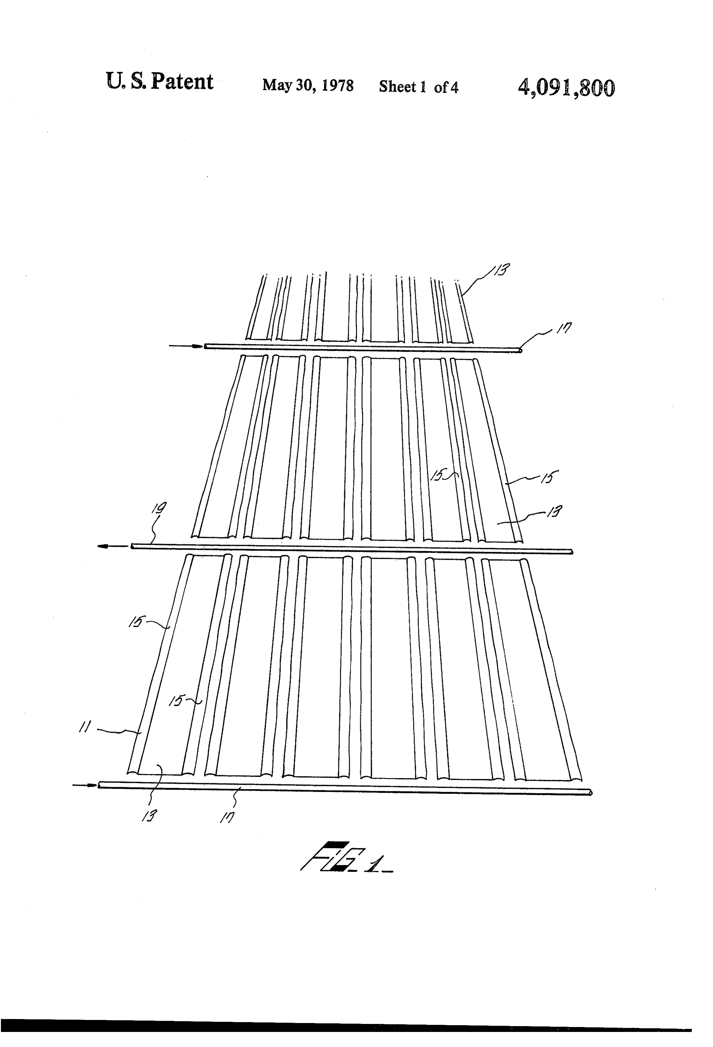
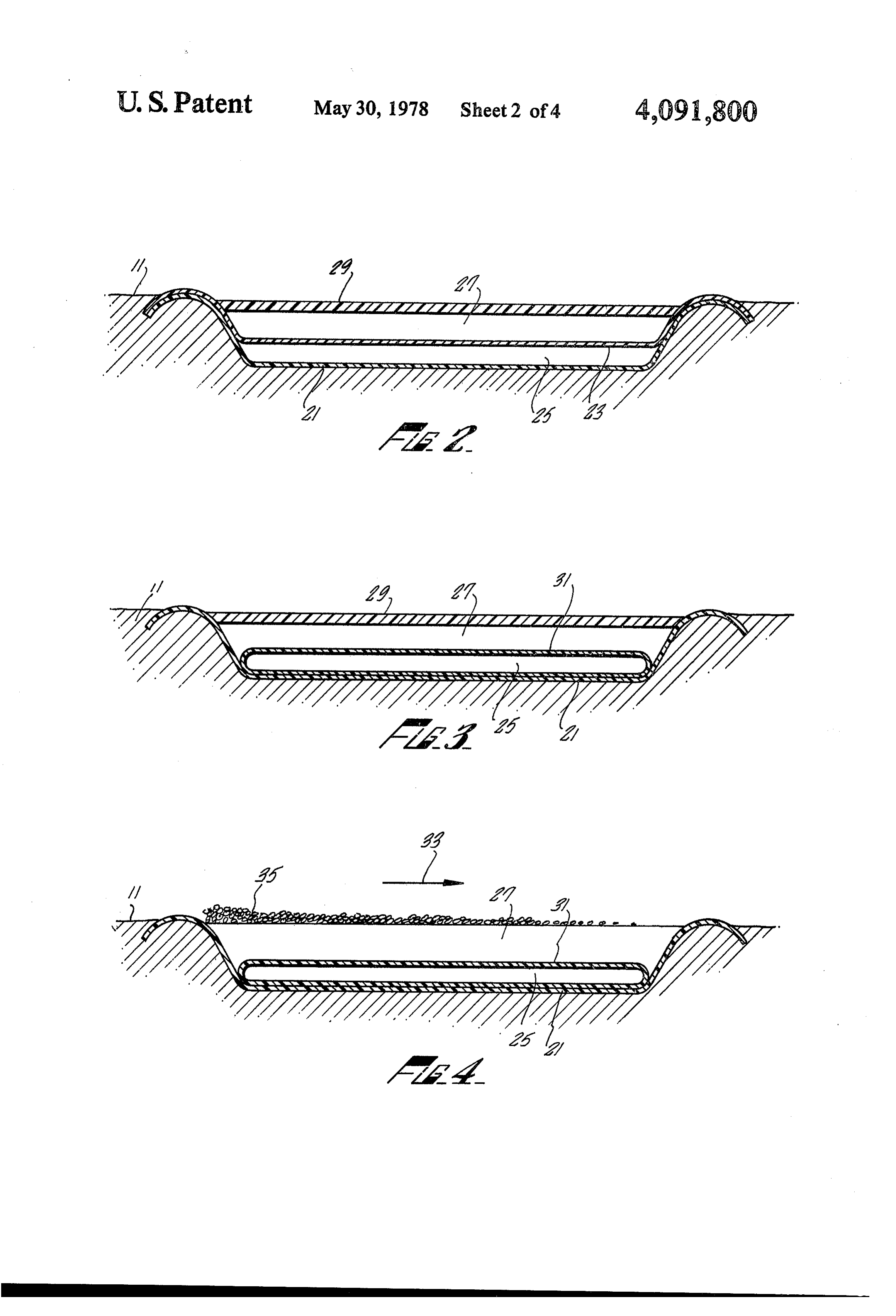
hot fluid at the bottom of the pond does not circulate by 1 is a perspective of an array of elongated shal convection and bring the heat close to the exposed low trenches that make up a large-scale solar pond; upper surface of the pond for reradiation; and (3) the a solar FIG. 2 is an end cross-section of one embodiment of need to minimize evaporation from the exposed surface pond trench;
of the pond. There is also considerable difficulty in 55 ofFIG. 3 is an end cross-section of another embodiment a solar pond trench;
volved in extracting heat from solar ponds since the removal to a heat exchanger, for example, and subse FIG. 4 is an end cross-section of a third embodiment quent replacement of the hot bottom liquid of the pond of a solar pond trench;
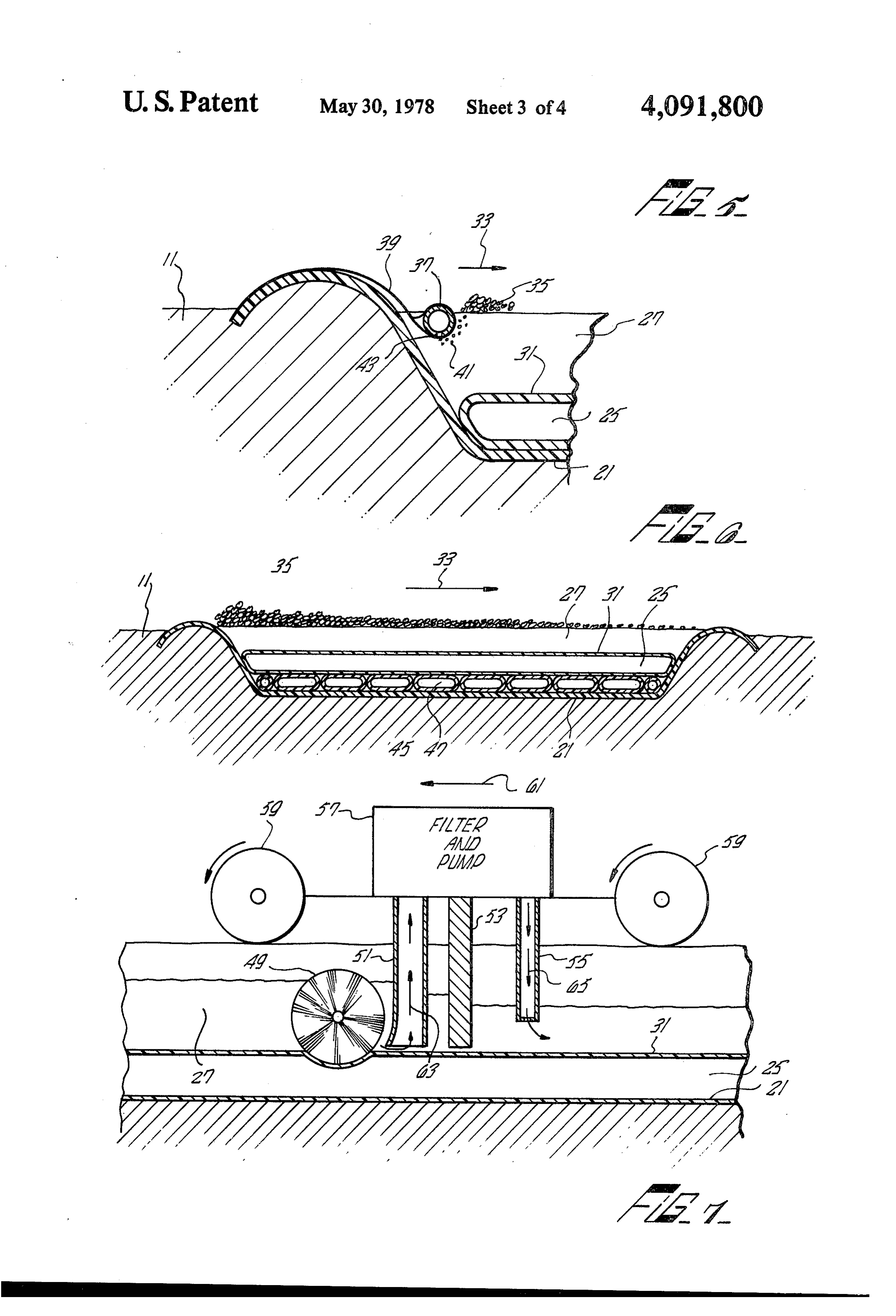
induces convection. FIG. 5 is a partial end cross-section of an aerating OBJECTS AND SUMMARY OF THE device utilized in the solar pond trench of FIG. 4; INVENTION FIG. 6 is an end cross-section of a fourth embodiment of a solar pond trench;
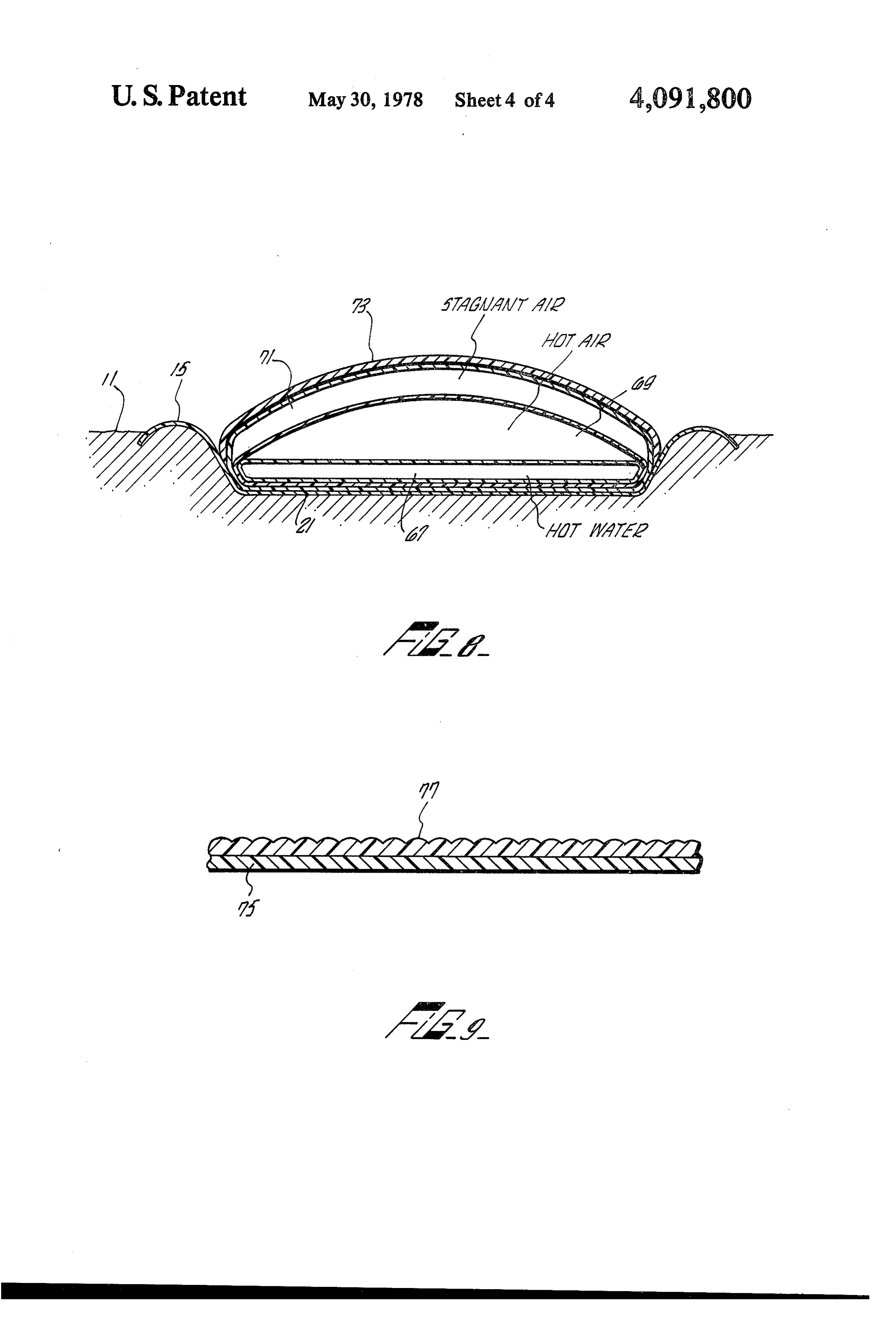
An object of this invention is to provide low-cost, FIG. 7 is a cross sectional illustration of a cleaning large solar energy collectors having considerable ther mechanism for the solar pond trenches of this invention; mal energy storage capacity. 65 FIG. 8 is an end cross-section of a fifth embodiment Another object of this invention is to provide Solar of a solar pond;
heated ponds that economically maintain the fluid in the FIG. 9 is an abstracted illustration of a laminate struc ponds free from dirt, dust and other debris. ture used for covering a solar pond.
Page 7scan →
DESCRIPTION OF THE PREFERRED example, if one side of a square representing the area of EMBODIMENTS the trenches is over 20 to 30 times the depth of water in each trench, it is quite feasible that such ponds can serve
A large scale solar pond of a size on the order of as very efficient storage systems. For many soils such as several acres may be constructed as shown in FIG. 1 by 5 sandy ground, it may take several weeks for the ground forming an array of narrow, elongated trenches 13 that and temperature within the pond to reach temperature are approximately one to two feet deep. The trenches equilibrium. Once that occurs the stored heat within the may be carved out of a flat expanse of land by bulldoz ground can supply the pond with heat during extended er-type equipment. The dirt removed from each shal periods of sunless days.
low elongated trench is left around its perimeter as a O The heat-containing fluid 25 in the pond of FIG. 3 is berm 15 which is utilized in a manner that will be here slowly pumped through a heat exchanger for the pur inafter explained. Manifold piping for a heat-carrying pose of removing the thermal energy stored therein. fluid is preferably laid so that there is a pair of inlet A third alternate preferred embodiment for the pres manifolds 17 for each outlet manifold 19. It would be ent invention is illustrated in FIG. 4. Rather than utiliz understood, however, that the solar pond array 11 of 15 ing a transparent solid or silloons suspended in water 27 FIG. 1 should not be limited to such a manifold arrange to cover the heat-containing fluid within hose 31, this ment. Other well known manifold arrangements could embodiment utilizes water containing a foaming agent be used with equal effectiveness. such as is used in fire fighting foams which is well A first preferred embodiment for one of the trenches known to produce an abundance of suds 35 when aer in the solar pond of FIG. 1 is illustrated in FIG. 2. After 20 ated. An example of a sudsing agent that may be used is the narrow, elongated trench is formed in the Earth's anise extract. The suds are generated on one side of the surface 11, the interior surface of the trench is covered trench or the other, depending on the direction 33 of the with black sheeting 21. A heat-absorbing fluid prefera prevailing wind at the time. The suds 35 are generated bly water occupies a height of up to approximately one by aerating the water 27 containing the foaming agent. foot of the bottom of the trench. The water may have a 25 Besides providing some thermal insulation it acts as a chemical such as salt dissolved therein to increase its skimmer, removing dirt particles landing on the surfae density. A transparent polyethylene sheet 23 is placed of the water. As the suds are driven by the prevailing over the water 25 at the bottom of the trench. The wind 33, to the other end, the dirt particles are skimmed remaining height of the trench may then be filled either along and deposited therein. The thermal energy stored with clear water 27 or with a transparent solid such as 30 within the higher temperature fluid 25 in the thin, trans a gelatinous mass. This prevents heat loss from the parent polyethylene tube 31 is removed by slowly trench. In either case, a layer of blister-pak 29 is laid pumping it through a heat exchanger by way of the over the top of the trench to further prevent heat loss manifolding pipes. (FIG. 1) and maintain the interior free from debris. Blister-pak 29 A preferred aerating device for generating the suds is a well known packing material that has trapped pock 35 35 is shown in FIG. 5 as consisting of a plastic aerating ets of air formed between two thin plastic sheets. The tube floating in the fluid 27. The aerating tube 37 has an black, polyethylene liner 21, the transparent plastic 23 unsymmetrical cross-section, thereby causing one side and the blister-pak covering material 29 is conveniently of the tube to always float facing into the water. A held down by the berm along the perimeter of the series of holes 43 in this side permits air piped through trench. the tube to be ejected as air bubbles 41 therefrom. This The water at the bottom of the trench 25 assumes the causes the suds 35 to be generated. The tube is held highest temperature becauses of its contact with the close to the side of the trench by any convenient fasten black liner 21. This heat may be removed by slowly ing means such as a cable 39.
circulating this water through a heat exchanger by way Another alternate preferred embodiment of a trench of the inlet and outlet manifolds shown in FIG. 1. 45 that can be used in the solar pond of FIG. 1 is illustrated An alternate preferred embodiment for a trench to be in FIG. 6. In this embodiment, rather than pumping the used in the solar pond of FIG. 1 is illustrated in FIG. 3. heat-containing denser than water fluid 25 contained In this embodiment the high-temperature fluid at the within the polyethylene tubing 31 through a heat ex bottom of the trench is contained within a thin wall, changer, heat is removed from the solar pond by a transparent polyethylene tube 31. The tube conforms to 50 seamed air mattress type tube 45. This tube 45, rests the bottom of the trench. It may be surrounded by adjacent to the black polyethylene liner of the trench water, in which case the solution 25 within the tube 31 and adjacent to the denser than water heat-absorbing is preferably denser than water, for example, a brine fluid 25 in the tubing 31. The air mattress tubing 45 solution. Rather than resting in water, the tube 31 may preferably contains a fluid such as water. It absorbs the be covered with a transparent solid of the type above 55 heat from the solar pond without disturbing the stag noted. The top of the pond is covered by blister-pak 29 nant condition of the fluid 25 in the tubing 31. The or some other convenient transparent covering. If the water contained therein may be supplied to a heat ex tube 31 is surrounded by water, siloons which are air or changer or directly to a heat engine. liquid-filled plastic spheres may be used as a covering. The efficiency of the solar pond decreases as the The tubing 31 in the trench containing the denser surface water becomes murkier and the plastic tubing than water, heat-absorbing solution 25 becomes hot containing the denser than water heat-absorbing fluid from the sun's rays reaching it directly and by conduc becomes dirty. In order to provide for a convenient tion from the hot black liner 21. The black liner absorbs method of cleaning the trenches when such a condition a substantial amount of thermal energy from the Sun occurs, the mechanism illustrated in FIG. 7 is prefera shine. Heat is also conducted into the ground 11 Sur 65 bly utilized. The mechanism for cleaning the surface rounding each trench. If the overall area of the assem fluid and the surface of the heat-absorbing fluid tubing bly of trenches illustrated in FIG.1 making up the solar straddles the width of a trench. It rides on the berm of pond is large compared to the depth of each trench, for the trench it is cleaning, moving along its length, both 8 filtering the surface water within the trench and clean warmed and a monolayer of small glass beads is pressed ing the surface of the plastic tubing containing the heat absorbing fluid. Assume that the mechanism is moving into its surface, the glass substance will act in the same way that a glass pane does in a conventional flat plate along the length of the trench is a direction 61. It is absorber, yet the tube 77 will remain flexible and suit mounted on four wheels, a pair of wheels 59 being able for its purpose as set forth above. For some uses, shown as riding on one side of the trench on a berm 15. short lengths of fibers of glass, or scales of glass may be The mechanism comprises a filter and pump device 57 likewise pressed onto the surface of 79. well known in the art for filtering sediment and debris In summary what has been described is a low cost from a fluid. A rotating brush mechanism 49 mounted in large solar energy collector that has considerable ther the front within the water is the width of a trench. It 10 mal rotates as the cleaning mechanism moves in the direc lector is provided in capacity.
energy storage Such a solar energy col tion 61, freeing any debris that has been deposited on are economically maintained andsolar the form of heated ponds that constructed to pro the tubing 31. As this debris is freed, an intake manifold vide optimum efficiency in the absorption of solar en 51 sucks in a substantial portion of fluid in a direction ergy, in the storage of thermal energy in the fluids in the 63, supplying it to a filter 57. The filtered water is 15 pond and in the land on which the pond is built, and in dumped out again by way of outlet manifold 55, in a the removal of heat from the pond. direction 65, on the opposite side of a moving dam 53. Obviously modifications and variations of the present In situations that provide for more advantageous use of a gaseous fluid such as air for the removal of heat isinvention are possible in light of the above teachings. It to be understood, therefore, that within the scope of from the solar pond, the alternate preferred solar pond structure of FIG. 8 may be utilized. The construction of the appended claims the invention may be practiced otherwise than as specifically described, while still ap the trench is identical to that used for the solar ponds utilizing a liquid for removing heat therefrom. A black proaching the efficiency of glass-plate flat plate collec plastic liner 21, such as made by Dow Chemical or The tors but using the sturdier, cleanable, cheaper and more Liberty Vinyl Corporation, lines the trench after it is 25 convenient construction of plastic tube material. What is claimed is:
formed in the soil 11, A heat-absorbing fluid, such as 1. A solar energy collecting pond, comprising: water 67 is preferably contained in transparent polyeth ylene tubing 31. This tubing 31 is in turn contained a trench formed in the Earth's surface; within a larger tube 75 likewise of transparent, polyeth a heat-absorbing, liquid-impervious material lining ylene plastic, Air is circulated through the chamber 69 30 said trench;
between the tubing 31 and 75. The tube 75 containing a first heat-absorbing liquid contained by the lined the tube 31 therein is in turn contained with a yet larger trench, said liquid being stagnant; tube 77 creating another chamber 71. This chamber a second heat-absorbing liquid contained in a tube of preferably contains stagnant air. Thus, there are in ef transparent plastic material within said first liquid, fect, three chambers adjacent to each other, in se 35 said tube of heat-absorbing liquid conforming to quence, within the trench. The chamber 67 containing a the bottom of said trench adjacent to said heat heat-absorbing fluid such as water is adjacent the bot absorbing lining material, said second liquid flow tom of the trench. The chamber 69 containing a gas, ing through its tube; and such as air, is adjacent the chamber 67 containing the a covering means floating on and suspended by said heat-absorbing fluid. This flowing air 69 removes the first liquid permitting light rays to pass there heat from the solar pond. The third chamber 71 is adja through into said first liquid for maintaining said cent to the heat removing chamber 69 covering it. This first liqid relatively free of dirt and debris and re third chamber contains an insulating fluid such as stag ducing heat loss therefrom. nant air therein to preventheat loss from the solar pond. 2, The solar energy collecting pond of claim 1 The tube 77 which has a side that is exposed to the 45 wherein said trench has a length equal to or greater than direct rays of the sun. That side is covered with a mate twenty times its depth.
rial 73 that has the characteristics of blocking ultravio 3. The solar energy collecting pond of claim 1 let and infrared radiation. wherein said lining material comprises black sheeting A convenient and well known ultraviolet radiation material.
blocking material is para-amino benzoic acid. This ma 50 4. The solar energy collecting pond of claim 1 terial is incorporated into a transparent plastic sheeting wherein said second heat-absorbing fluid, comprises a material 79. By covering the sheeting material with a salt and water solution.
layer of hydrogel 81, a type of which is sold under the 5. The solar energy collecting pond of claim 1 common name of "Hema,” the additional feature of wherein said covering means, comprises a layer of blis infrared radiation blocking is provided. The hydrogel 55 ter-pak, utilized absorbs water from the air and provides a water 6. The solar energy collecting pond of claim 1 layer equivalent to a water film approximately a few wherein said covering means, comprises a layer of ge thousandths of an inch thick. A well-known material latinous mass.
capable of holding such water is known as hydroxy 7. The solar energy collecting pond of claim 1 methyl ethyl acrylate which is an ethylene glycol esther wherein said covering means, comprises: of acrylic acid. Such astructure prevents the sun's ultra a first layer of a gelatinous mass; and violet rays from deteriorating the plastic tubing utilized a second layer of blister-pak over said first layer. in the solar pond of FIG. 8 and also blocks in the infra 8. The solar energy collecting pond of claim 1 red radiation given off by the heat-absorbing fluid 67 in wherein said covering means comprises a layer of small, the solar pond. 65 hollow glas spheres,
Another preferred way of blocking ultraviolet and 9. The solar energy collecting pond of claim 1 absorbing infrared radiation that may be used in this wherein said covering means, comprises a layer of fire connection, follows. If the sheeting material 79 is fighting foam.
Page 9scan →
10. The solar energy collecting pond of claim 9, fur. absorbing liquid relatively free of dirt and debris ther comprising: means for continually forming said fire and reducing heat loss therefrom. fighting foam. 13. The solar energy collecting pond of claim 12 11. The solar energy collecting pond of claim 10, wherein said first heat-absorbing liquid comprises wa wherein said forming means comprises: ter.
a layer of water; 14. The solar energy collecting pond of claim 12 a foaming agent contained in said water; and a source of air for continually aerating said layer of wherein tained in said second liquid comprises salt water, con a clear polyethylene thin wall tubing.
Water, 12. A solar energy collecting pond, comprising: 15. The solar energy collecting pond of claim 12 O wherein said third heat-absorbing liquid comprises wa a trench formed in the Earth's surface;
a heat-absorbing, liquid-impervious material lining ter, contained in a clear polyethylene thin wall tubing, said tubing being between and adjacent to the lining said trench; material of said trench and the tubing containing said a first heat-absorbing liquid retained in the lined second heat-absorbing liquid. trench, said liquid being stagnant; 15 a second heat-absorbing liquid contained in a tube of 16. The solar energy collecting pond of claim 12 plastic material along the bottom of said trench wherein said covering means, comprises: a transparent sheet of plastic; and within said first heat-absorbing liquid, said second liquid being stagnant; a coating of hydrogel containing a quantity of water a third heat-absorbing liquid contained in a tube of 20 equivalent to a layer of water at least 0.003 inches plastic material adjacent said second heat-absorb thick, disposed on said plastic sheet. ing liquid, said third heat-absorbing liquid flowing 17. The solar energy collecting pond of claim 16 through its tube for removing heat from said pond; wherein said transparent sheet of plastic is made from and polyethylene.
means for covering said trench, said means floating 25 18. The solar energy collecting pond of claim 16 on and suspended by said frost liquid for permitting wherein said coating of hydrogel is made from hydroxy light rays to pass therethrough into said first heat methyl ethyl acrylate.
absorbing liquid and maintaining said first heat . . . . .
Provenance
- Collection
- Patents citing this work
- Pages
- 9
- Method
- pdftotext (the PDF's own text layer) + pdftoppm 300dpi page scans
- Patent office record
- patents.google.com →
- Source
- Google Patents citing-documents table
- Assignee
- The United States Of America As Represented By The Administrator Of The National Aeronautics And Space Administration
- Published
- 1978-05-30
- Transcribed from
- patentimages.storage.googleapis.com →