

patent · US4098264A
Solar liquid heating apparatus
4 July 1978
Text
Page 1scan →
Brokaw
(54 solar liquid heating apparatus
(76) Inventor: Carmel,
Hal R. Brokaw, P.O. Box 273,
5ll Int. C.’................................................. F24J 3/02 52 U.S.C. .................................... 126/271; 237/1 A
1,425,174 8/1922 Carter et al. ........................ 126/27 1,951,403 3/1934 Goddard ..... ... 126/271 3,847,136 11/1974 Salvail ..... 126/271 3,861,379 1/1975 Anderson, 126/270 3,903,700 9/1975 Glickman ............................. 126/270 3,917,942 11/1975 McCay ................................. 126/270 3,931,806 1/1976 Hayes ................................... 126/271 3,985,119 10/1976 Oakes ....... ... 126/271 3,990,430 1 1/1976 Robertson ............................ 126/271
4,000,734 1/1977 Matlock et al....................... 126/271 Primary Examiner-Kenneth W. Sprague
Assistant Examiner-James C. Yeung
Attorney, Agent, or Firm-R. S. Sciascia; G. J. Rubens
A solar apparatus is provided for heating liquids such as water, to a high temperature by utilizing a movable parabolic heat collector to concentrate the sun's rays associated with a special piping arrangement to obtain progressive liquid pre-heating; a collector tracking de vice including photocells and a collimating system for controlling the movement of the collector to maintain alignment with the sun; a device for modulating the flow of the heat transfer liquid between the collector and the storage to maintain optimum heat replenish ment therebetween; and also a vacuum insulated heat exchanger to isolate the heat transfer liquid from the water being heated.
6 Claims, 8 Drawing Figures
Aygzaoa
Drawings
Page 2drawing sheetscan →
Page 3drawing sheetscan →
Page 4drawing sheetscan →
Page 5drawing sheetscan →
Page 6scan →
Solar liquid heating apparatus statement of the objects of the
Invention
Statememt of governmental
INTEREST It is a principal object of this invention to provide a 5 more efficient solar heater by having a movable heat
The invention described herein may be manufactured collector, or concentrator, capable of automatically and used by or for the Government of the United States tracking the sun during daylight hours. of America for governmental purposes without the Another important object is to provide a solar con payment of any royalties thereon or therefore. centrator having an arrangement of pipes to preheat the 10 circulating working liquid to be heated.
Background of the invention
This invention relates to solar heating apparatus, and Still further objects are to provide a solar heater with more particularly to such apparatus and system that an flow improved heat exchanger; and a modulated fluid control system that adjusts the rate of flow for concentrates the solar energy, and automatically tracks the sun throughout its daylight path to achieve a high 15 optimum heating conditions. temperature heat transfer, and for controlling and main of this invention and
Other objects many of the attendant advantages will be readily appreciated as the same taining the desired temperature of the stored liquid becomes better understood by reference to the follow medium.
ing detailed description
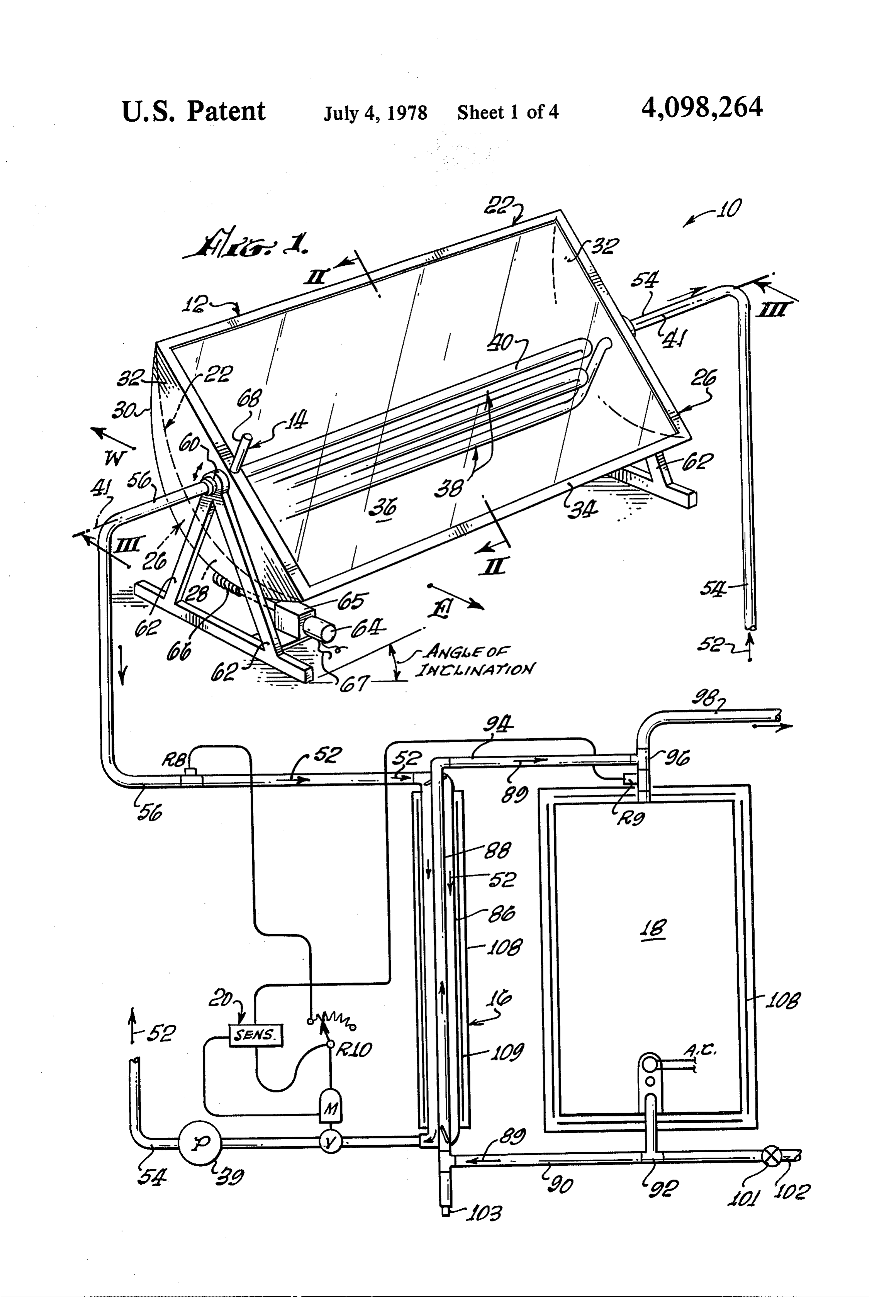
Solar water heaters have been employed for many with the accompanying drawings. when considered in connection years throughout the world. They can be classified 20 generally in two categories, namely panel solar heaters, BRIEF DESCRIPTION OF THE DRAWINGS and concentrator solar heaters, depending on the tem perature requirements of the particular installation. The theFIG. novel 1 is a general arrangement of the components of solar heater apparatus, with the concentrator concentrator type of solar heater, of which the present invention is an example, employs a parabolic or cylin 25 shown in isometric view.
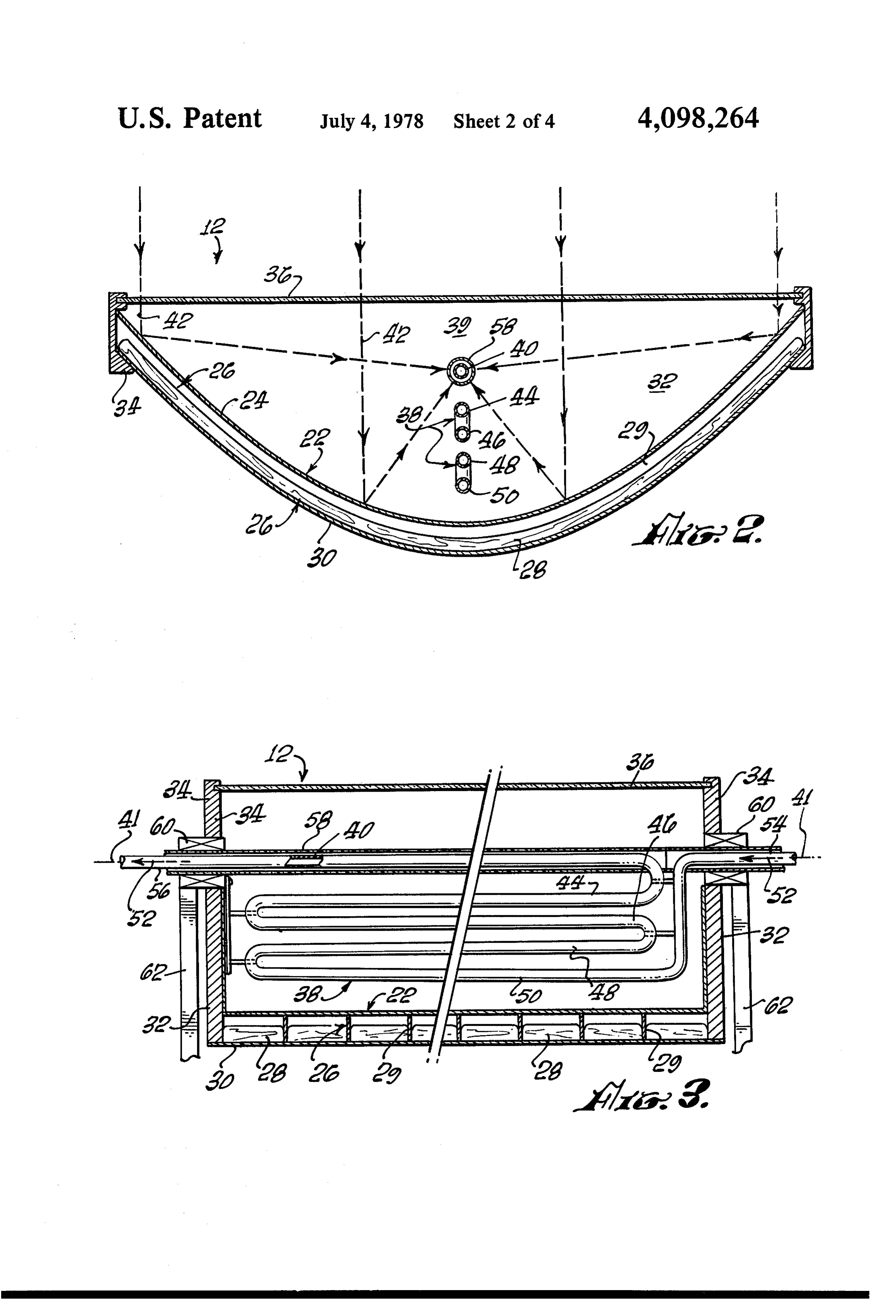
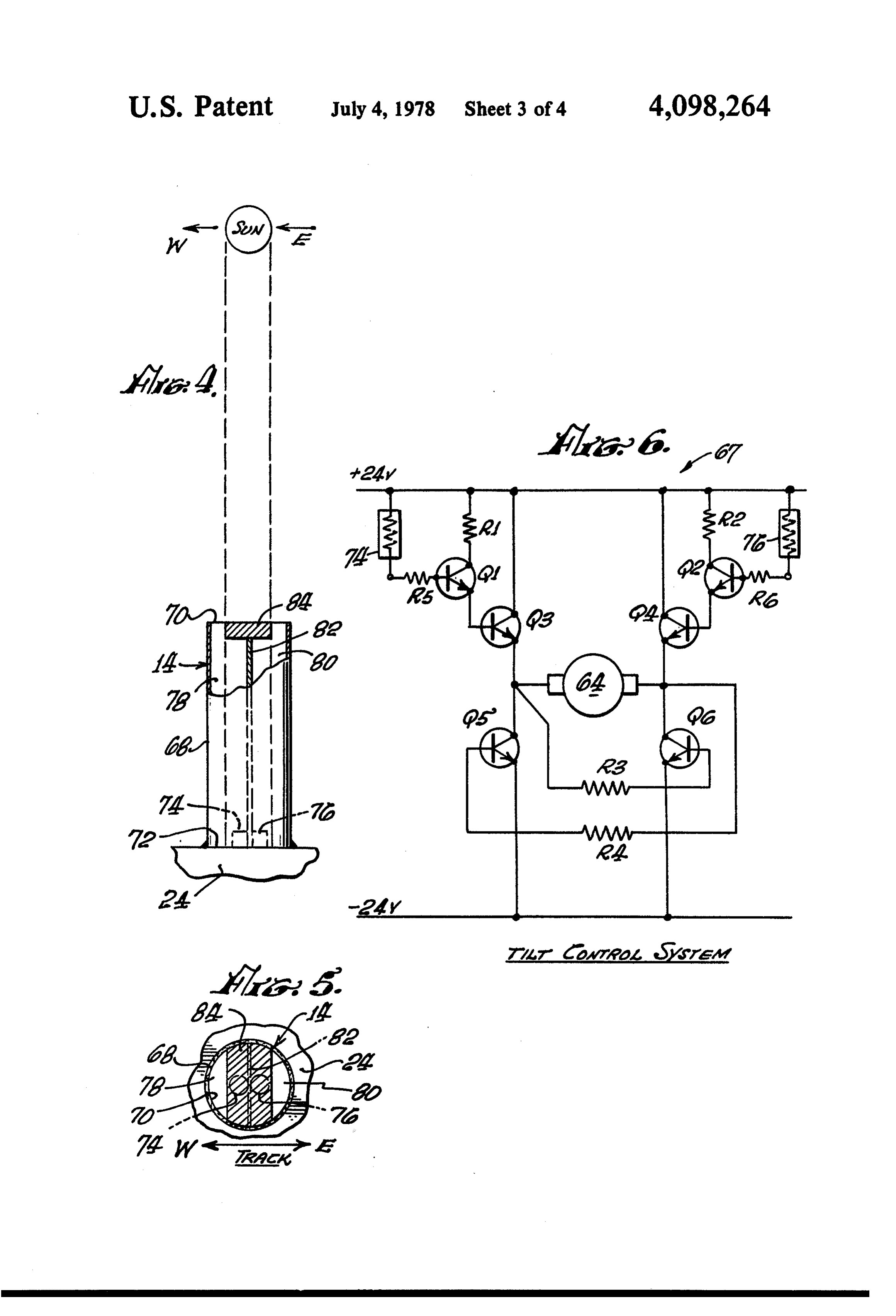
FIGS. 2 and 3 are sectional views of the novel con drical heat collector to concentrate and focus the re flected solar energy for producing temperatures above showing centrator taken along lines II-II and III-III of FIG. 1 212° F to be suitable for use in steam heating applica the piping arrangement and other details. tions, air conditioning, refrigeration systems, power FIGS. 4 and 5 are side and top views, respectively, of a collimator housing photocells to sense the position of generation, as well as other suitable heating applications 30 the up to 500' F. sun.
In order to fully utilize a concentrator type of solar FIG. 6 is a tracking circuit utilizing the collimator of FIGS. 4 and 5 for controlling the movement of the solar heater, it is desirable to track the sun, and accordingly, COncentrator.
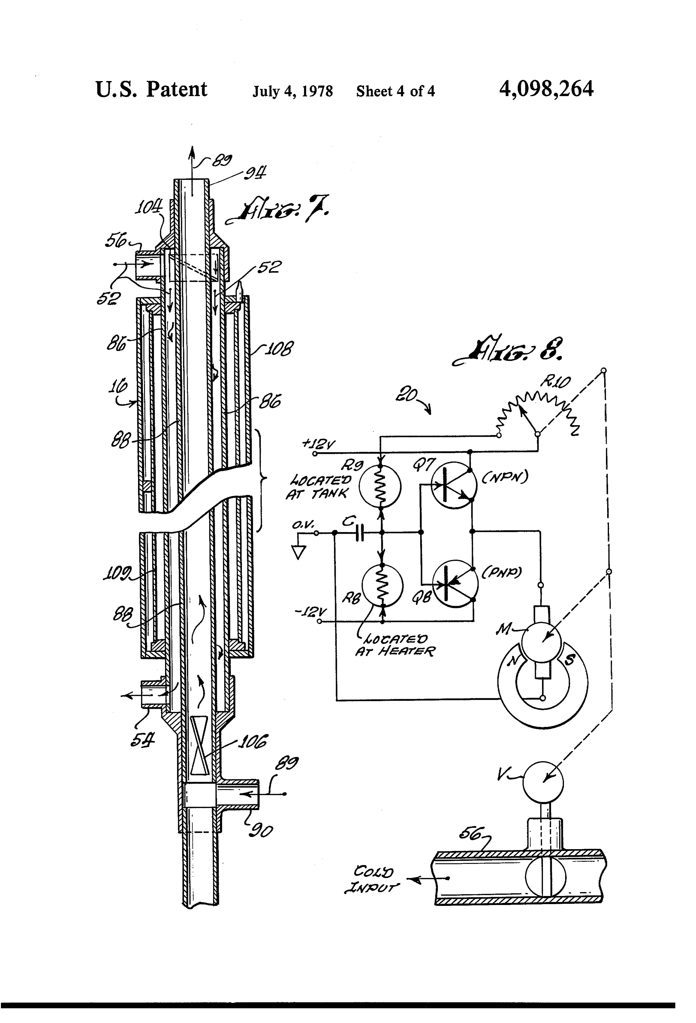
it is conventional to mount the reflecting surface for rotation about one or more axes. Examples of such 35 FIG. 7 is an enlarged longitudinal sectional view of a construction is illustrated by U.S. Pat. Nos. 2,182,222 vacuum insulator heat exchanger.
and 820,127. FIG. 8 is a temperature sensing and modulating cir However, neither of these patents nor the others in cuit.
the art, disclose a suitable control means to enable the DESCRIPTION OF THE PREFERRED heat collector to be continuously and automatically EMBODIMENTS guided and oriented in the most advantageous position with respect to the sun throughout its daylight travel. Referring to the drawings where like reference nu Nor does the art disclose the novel techniques for sens merals refer to similar parts throughout the figures ing and controlling the temperature of the stored liquid there is shown in FIG. 1 a general arrangement of the medium throughout the day. 45 basic components of the novel solar heater 10 as may be
Summary of the invention
utilized preferably for steam generation. It should be understood that this basic solar heater can be incorpo
The solar heater is provided with an improved solar rated in many different applications, such as forced air heat concentrator having a network of preheating coils heating systems, air conditioning systems, steam or positioned in the mouth of a parabolic reflector, which SO electric power generation, etc.
coils are connected to a main heating tube positioned at The illustrated solar heater 10 comprises at least one the focal axis of the parabolic reflecting surface. This heat concentrator assembly 12; a solar collimator track arrangement of coils enables the temperature of the ing apparatus 14 for the concentrator assembly; a heat circulating fluid medium to be preheated initially to exchanger 16 connected by piping between the concen above 150 F before passing through the main heating 55 trator assembly 12 and a hot water storage tank 18; and tube. a temperature valve sensing system 20 electrically con An automatic tracking circuit includes photocells and nected to concentrator 12 and to tank 18. a collimator to follow the sun, and to control the heat As shown in FIG. 2, concentrator assembly 12 in collector driving means to maximize the heat transfer cludes an inner reflector panel 22 having a mirrored throughout the daylight hours. 60 outer surface 24, the panel being configured in cylindri The solar heater preferably employs a unique heat cal parabolic shape by an aluminum rectangular frame closed loop exchanger that transfers the solar heat ab 26. A layer of foil surfaced, fiberglass insulation 28 is sorbed by the working fluid mediums to a hot water positioned between frame ribs 29 and sandwiched be storage loop. tween inner panel 22 and outer aluminum panel 30. A temperature sensing circuit and modulating valve 65 Panel 30 has a white enamelled finish to reduce solar device compares the temperatures at the heat concen heat loss. Concentrator assembly 12 is provided with trator and the storage facility to maintain optimum heat flat end walls 32, which have a similar sandwiched replenishment therebetween. fabrication as the parabolic section.
Page 7scan →
The edges of the combined sandwich panel assembly tions. However, if greater heat transfer efficiency is are supported together by channelled side frame mem desired by also following the north/south inclination of bers 34, which are also channelled to support one tem the sun throughout the year, reflector assembly 12 can peratured glass cover 36 for protecting the reflecting be pivotally mounted to be tilted manually or power surface 24 from dirt and moisture, and for reducing heat driven in a manner similar to that described for the losses from the wind. tracking mode.
As is best illustrated in FIGS. 2 and 3, concentrator One of the unique features of this invention is to mini assembly 12 houses a unique piping system 38 made of mize heat loss in the early morning and late afternoon copper or the like through which liquids can be circu by providing concentrator drive motor 64 with an auto lated by a pump 39 (FIG. 1) in a simple direct hot water 10 matic tracking control circuit 67 to track the east-to system; but preferably a working fluid, such as "Dow west path of the sun throughout the day. As shown therm, '' in a closed loop system using heat exchanger broadly in FIG. 1, and detailed in FIGS. 4-6, tracking 16, as illustrated in FIG. 1, but which can be incorpo of circuit 67 includes collimator 14 supported on the front rated in tank 18. reflector frame 24 at the centerline of the concentra Piping system38 includes a circuitous arrangement of 15 tor. Collimator 14 comprises a cylindrical housing 68 spaced, parallel pipe sections traversely aligned cen having an open end 70, and a closed end 72 fixedly trally the concentrator assembly, preferably oriented mounted to frame 24 providing a perpendicular orienta normal to the reflecting surface and with the rotational tion with respect to concentrator frame 24. At least two axis of the collector. An uppermost superheat pipe 40 is photocells, or the like, 74 and 76 are mounted to hous positioned along the focal axis 41 of the parabolic panel 20 ing end 72, being spaced apart and oriented in an east 22 so as to be in the path of the directly reflected solar west alignment on each side of concentrator centerline light rays 42, (FIG. 2) the remaining preheat pipes 41. Housing 68 is separated into two longitudinal com 44-50 being suspended inwardly therefrom and subject partments 78 and 80 by a wall 82 forming a light barrier to random reflected solar light rays. The path of the between the two photocells. The upper end of wall 82 working liquid passing through these pipes is indicated 25 supports a barrier plate 84 which provides a shadow to by broken arrow 52 (FIGS. 1 and 3) entering concentra overlap photocells 74 and 76 when the sun is substan tor 12 at inlet pipe 54 and passing through preheat pipes tially aligned with the longitudinal axis of the collimator 44-50 and finally through main heater pipe 40 which 14. In this position the collector is properly oriented superheats the liquid prior to discharge at outlet pipe 56. with respect to the sun to achieve maximum heat trans fer efficiency. Whenever the collimator, and the con
Outlet pipe 56 is located nearest to heat exchanger 16, 30 centrator, or storage tank 18 when no heat exchanger is utilized, become misaligned in any E-W position with and is suitably insulated. Superheat pipe 40 may be respect to the sun because of interrupting clouds, etc., enclosed within an evacuated glass tube 58 for insula the respective photocell will be illuminated thereafter tion purposes. In systems that may utilize more than one by the sun and heat concentrator 12 will be driven to reflector module, only the module located at the cold 35 cover said photocell, and restore the aligned condition end of the liquid exchange system need be provided without requiring a continuous current. with the preheater tubes. As shown in FIG. 6, tracking circuit 67 incorporates Concentrator panel 22 and its supporting frame 24 are photocells 74 and 76 in a simplified version of the appa rotatably mounted at each end around axis 41 through ratus, suitable for small heating systems such as may be tubular roller bearings 60 secured in triangular side operable on a plus and minus 12-volt D.C. power supports 62. Glass tube 58, which encloses superheat source, connected across concentrator drive motor 64, pipe 40, laterally terminates at a vacuum seal, not which in this application is a reversible 24-volt D.C. shown, where the preheat pipe section connects to pipe motor. For larger installations, an A.C. motor with 40 near inlet 54 to enable preheat pipe 50 to extend reversible relays, or thyristor control, can be employed. through and remain fixed within bearings 60. Thus, the 45 Photocell 74 is provided with a motor circuit includ entire piping system 38 remains stationary while con ing transistors Q1, Q3, Q6, current limiting resistor R1, centrator assembly 12 pivots thereabout, an arrange and bias limiting resistors R3 and R5. Photocell 76 is ment which simplifies construction and reduces the provided with a motor circuit including transistors Q2, weight of the reflector assembly to be driven by motor Q4, and Q5, current limiting resistor R2, and bias limit 64 through gear reduction 65 worm 66. 50 ing resistors R4 and R6.
Concentrator assembly 12 of FIGS. 1-3 is designed Operation of the tracking circuit is obvious from to be movable about a single axis 41, i.e., north/south FIG. 6. For example, if photocell 74 is illuminated by orientation and at a given inclination, so as to be able to the sun current flows through Q1, Q3, motor 64, and pivot from east to west tracking the sun from sunrise to Q6, driving the concentrator 12 in a direction to un sunset. Since optimum heating is obtained when the axis 55 cover photocell 76. When the sun strikes photocell 76, is parallel to the local latitude, or even 10 more, it may the current flows through its respective motor circuit to be desirable to raise the north end of the assembly to drive concentrator 12 in the opposite direction. As long compensate for the sun's inclination. A suitable roof as both photocells are shielded from the sun, no power location or other support may provide the required is consumed and the concentrator is properly aligned inclination. The precise angle of concentrator assembly 60 with the sun in its optimum position. 12 facing the south will depend on the seasonal inclina As previously stated, if desired, concentrator 12 can tion. Optimum heating the year around is achieved by a be provided with a tilt drive mechanism and a tilt circuit fixed tilt angle (as shown in FIG. 1) from 33 at the San identical to tracking circuit 67. Tracking could also be Diego area to 48 at the northern U.S. Border; 10 more done at a steady rate, with corrections being made by will benefit winter heating. The sun inclination is plus 65 the above tracking circuit.
and minus 23' from this equinox angles. Providing con Another important feature of the invention resides in centrator 12 with a fixed tilted arrangement is the most the construction of heat exchanger 16, shown in detail simple and adequate for most contemplated applica in FIG. 7, hydraulically connected between concentra 8 tor heater 12 and hot water storage tank 18. The use of working fluid temperature rises higher, the process will the heat exchanger is necessary when a special working be repeated to again balance the system. fluid 52 is used instead of water; and it is highly desir Should a cloud shade concentrator 12 from the sun, able to use a working fluid in place of water in a heat or at sunset, the resistance of R8 will increase, lowering collector system to reduce undesirable deposits, to pre the voltage at C and to the base of Q8. This drives vent freezing, to prevent corrosion and electrolysis, and negative current through PNP transistor Q8 and motor to avoid the high steam pressures in high temperature M, thereby reversing the motor and starts closing valve systems with water. As shown in FIG. 1, the heat ex V; and R10 again balances the systems to stop motor M. changer is separated from tank 18, but the same basic O This not only starts and stops the working liquid flow heat exchanger can be located within the tank and pro from the collector, it also modulates the rate of working vide the same advantages to the storage system. liquid flow through the one or more collectors to main Exchanger 16 comprises two concentric tubes 86 and tain the optimum rate of flow for the conditions at any 88 having optimum dimensions, depending on the vol given time. If sunlight is plentiful, valve V will be ume required for the specific application. Outer tube 86 opened wide, but any condition that reduces the insola provides a circuit for the working fluid 52 and is con 5 heating tion will reduce the rate of working fluid flow until the condition improves. Whenever the temperature nected at its top to concentrator outlet 56, and at its bottom to concentrator inlet 54. Inner tube 88 provides in the tank at R9 is higher than the working fluid tem a circuit for the hot water 89, and at the bottom is con perature at R8, valve V will be closed until heating is nected via inlet pipe 90 and T-joint 92 (FIG. 1) from the again favorable.
colder, bottom of storage tank 18; and from the water The novel solar heat exchanger system described supply line via valve 101 and line 102. The upper end of above provides a more efficient and inexpensive manner tube 88 is connected by outlet pipe 94 to the upper end of utilizing solar energy.
of tank 18 through Tjoint 96. Hot water may be drawn Obviously many modifications and variations of the either from the exchanger 16 directly or from the top of 25 present invention are possible in the light of the above tank 18 via outlet pipe 98, as long as the steam pressure teachings. It is therefore to be understood that within does not exceed the water supply pressure. A drain 103 the scope of the appended claims the invention may be is provided on the bottom of the exchanger 16 to facili practiced otherwise than as specifically described. tate removal of any sediment in the water supply. Vanes I claim:
104 and 106 are inserted into the inlets, near 56 and 103 3O 1. Solar heating and tracking apparatus comprising: respectively, to provide a rotary flow to the liquids so a solar concentrator having a parabolic reflecting that cold water will travel to the outside and warm surface;
water toward the center of each tube to enhance the a main heater pipe supported along the focal axis of heat transfer therebetween. Heat exchanger 16 is pro said parabolic surface and being directly in the path vided with an evacuated outer insulating jacket 108, 35 of the reflected rays;
within which is mounted a concentric, cylindrical foil said pipe having an inlet and an outlet for the passage radiation barrier 109. Similar insulating means is recom of a liquid heat absorbing medium; mended for storage tank 18 and the hot water piping. a plurality of preheater pipes connected to the main Temperature sensing system 20, shown generally in heater pipe and disposed between the main heater FIG. 1, and in detail in FIG. 8, functions to prevent pipe and the reflecting surface; means for support cooling of the stored hot water in tank 18 by colder ing said solar concentrator for pivotal movement water from the heat concentrator system 12, which may about at least one axis for tracking the movement of occur during night time, or long periods of interrupted the sun;
sunlight. means for driving said concentrator around said axis Sensing circuit 20 is a simple comparison electrical 45 responsive to a given signal; circuit, which may also be powered by plus and minus tracking control means for following the path of the 12-volt D.C. batteries, and includes two identical sun and for generating the signal to control said thermistors R8 and R9. Thermistor R8 is located in heat driving means;
concentrator outlet pipe 56 and senses the temperature whereby the concentrator will be guided to track the of the heated working fluid leaving the concentrator, 5O sun's path to maximize the heat transfer throughout while thermistor R9 is located in upper portion of hot the daylight hours.
water storage tank 18 and senses the temperature 2. The apparatus of claim 1 wherein said tracking therein. Thermistor R8 is connected across NPN tran means comprises a collimator system housing at least sistor Q7, while thermistor R9 is across PNP transistor two photocells separated by a light barrier oriented Q8. The outputs of the transistors control a reversible 55 normal to the direction of apparatus travel, one photo 12-volt D.C. motor M ganged to a butterfly valve V cell located on each side of the respective axis, said located in concentrator inlet pipe 54 and to a rheostat photocells being electrically connected to a tracking R10. control circuit with said driving means. In operation, as the temperature of the working fluid 3. The apparatus of claim 2 wherein said control in the concentrator rises, the resistance of R8 decreases circuit includes two identical portions, one connected which raises the voltage at condenser C and at the base to each photocell, and said driving means includes a NPN transistor Q7, and positive current flows through reversible motor capable of being driven in opposite Q7 to drive motor M in the positive direction. This directions by respective circuit portions. movement starts the opening of valve V and moves 4. The apparatus of claim wherein: rheostatR10 to compensate for the resistance lost by R8 65 theheat outlet of said main heater pipe is connected to a exchanger comprising concentrically nested as it is heated. At a certain point, the sum of R8 and R10 will equal the value of R9, the voltage at Creturning to pipes spaced apart to form an outer passage there zero and the motor will stop as will valve V. If the between, the inner pipe forming an inner passage;
Page 9scan →
one of said passages connected to a liquid storage ated concentric chamber is provided around the outer tank, and the other passage connected to the inlet nested pipe, said evacuated chamber having a concen and outlet of said solar concentrator; trically spaced radiation barrier. baffle means fixedly mounted in the entrance of each 6. The apparatus of claim 1 wherein said reflecting passage in the heat exchanger for causing the liquid surface can be driven independently of the main pipe medium to have a spiral flow therethrough and by centrifugal action enhance heat transfer. and preheater pipe.
5. The apparatus of claim 4 wherein an outer evacu
Page 10scan →
United states patent and trademark office
Certificate of correction
INVENTOR(S) : Hal R. Brokaw
It is certified that error appears in the above-identified patent and that said Letters Patent are hereby Corrected as shown below: Claim 4, line , insert -- 1 -- after "claim".
eigned and sealed this
Second Day of January 1979
Attesting Officer Commissioner of Patents and Trademarks
Provenance
- Collection
- Patents citing this work
- Pages
- 10
- Method
- pdftotext (the PDF's own text layer) + pdftoppm 300dpi page scans
- Patent office record
- patents.google.com →
- Source
- Google Patents citing-documents table
- Assignee
- Brokaw Hal R
- Published
- 1978-07-04
- Transcribed from
- patentimages.storage.googleapis.com →