

patent · US4116790A
Method and apparatus for separation of fluids with an electric field and centrifuge
26 September 1978
Text
Page 1scan →
United States Patent (19)
Prestridge
(54) method and apparatus for
Separation of fluids with an
Electricfield and centrfuge
75 Inventor: Floyd Leon Prestridge, Tulsa, Okla.
(73) Assignee: Combustion Engineering, Inc.,
Windsor, Conn.
51 Int. C.’................................................ B03C5/00 (52) U.S. Cl. .................................... 204/188; 204/302;
(58) Field of Search .................... 210/73 R, 73 W, 84,
1,873,857 8/1932 Worthington et al. .............. 204/302
EMULSION -o-
Inlet
3,478,494 1 1/1969 Lustenader et al. ............. 210/243 X 3,772,180 1 1/1973 Prestridge ........................ 204/191 X 3,951,771 4/1976 Burger ................................. 204/190 3,971,718 7/1976 Reid ....................................... 210/84 Primary Examiner-William A. Cuchlinski, Jr.
Attorney, Agent, or Firm-Arthur L. Wade
Fluids are separated from each other by passing their mixture through an electric field and centrifuge in se quence. The drops of a first fluid dispersed in a second fluid are coalesced by the force of an electric field to a predetermined size. The mixture is then passed into a centrifuge which develops the force to move the co alesced drops away from the other fluids of the mixture without reaching the value at which fluid shear forces, between the coalesced fluid and the fluid in which the coalesced fluid is dispersed, will fragment the coalesced drops.
15 Claims, 4 Drawing Figures
Clean oil out
Water out
Drawings
Page 2drawing sheetscan →
Page 3drawing sheetscan →
Page 4drawing sheetscan →
Page 5scan →
range, the centrifugal force necessary to move the
METHOD AND APPARATUS FOR SEPARATION drops will develop shear forces between the liquids OF FLUIDS WITH AN ELECTRC FELD AND which will prevent further enlargement of the drop size. CENTRFUGE The mixture is therefore stabilized by centrifugal force BACKGROUND OF THE INVENTION at a dispersion which limits separation. To breach the limitation on dispersed drop growth by
In recent years the need for rapid, high volume li liquid shear, it is evident that dispersed drops must be quid/liquid separation in the oil industry has increased. enlarged to a size by another force which will enable Most of the secondary and tertiary recovery methods the drops to receive only enough centrifugal force to developed in the United States and Canada utilize large 10 move the drops in separation without developing the quantities of water, resulting in produced mixtures of oil shear force which will refragment the drops. and water which are difficult to separate. Even the major oil producing countries in the Middle East are SUMMARY OF THE INVENTION now beginning to produce ever increasing volumes of The present invention combines the electric field to brine with their oil, increasing the demand for high 15 coalesce small, dispersed, drops of liquid into larger volume desalting equipment. drops with the centrifuge generating G's on the enlarg New developments and processes in other industries ing drops which will move them into separation from are also requiring liquid/liquid separation equipment. A the liquid in which the drops are dispersed without the good example in the mining industry is the solvent ex traction processes. The chemical industry is utilizing G's the developing the shear force which will refragment enlarged drops. Further, the flow through the cen similar liquid ion exchange processes. All of these pro trifuge is oriented so the normal force of gravity will cesses require elaborate liquid/liquid mixing and/or supplement the centrifuge G's in further reducing the separating facilities. , . . .. retention time required for separation. The use of high voltage electric fields to force the The invention is in the process of moving a mixture of separation of oil field emulsions is a well known and 25 liquids accepted practice. These fields greatly speed the coales trifugalsequentially through an electric field and a cen cence and separation of immiscible liquids, over con electrodes placed to definethea invention force. Structurally, path is in energized between them for ventional heater treaters and settlers using mechanical their electric field through which the fluid mixture is aids to coalescence. However, considerable retention time is still necessary, and large vessels are required if 30 flowed. The path is then extended into a centrifuge large volumes of emulsion are to be processed in a short where the mixture has only sufficient G's placed upon it to move the coalesced liquid drops toward separation time.
without developing shear forces between the separating “Retention Time' is that period required for a first liquids. Further, the centrifuge is oriented vertically to fluid dispersed in a second fluid to settle into a single use the force body from which it can be removed. Many things will 35 rating the heavier of gravity to supplement the G's in sepa affect retention time. A large factor is the size of the liquids are withdrawn liquids downward while the lighter drops formed by the dispersed fluid. Considering grav upwardly from the centrifuge. ity to be the usual external force applied to the dispersed willOther features of the invention, and their advantages, be apparent from the disclosure of the drawings, drops, if the diameter of these drops are doubled, their falling velocity through the fluid in which the drops are the description of the drawings and the claims which dispersed will be increased 10 times under Stokes Law. follow.
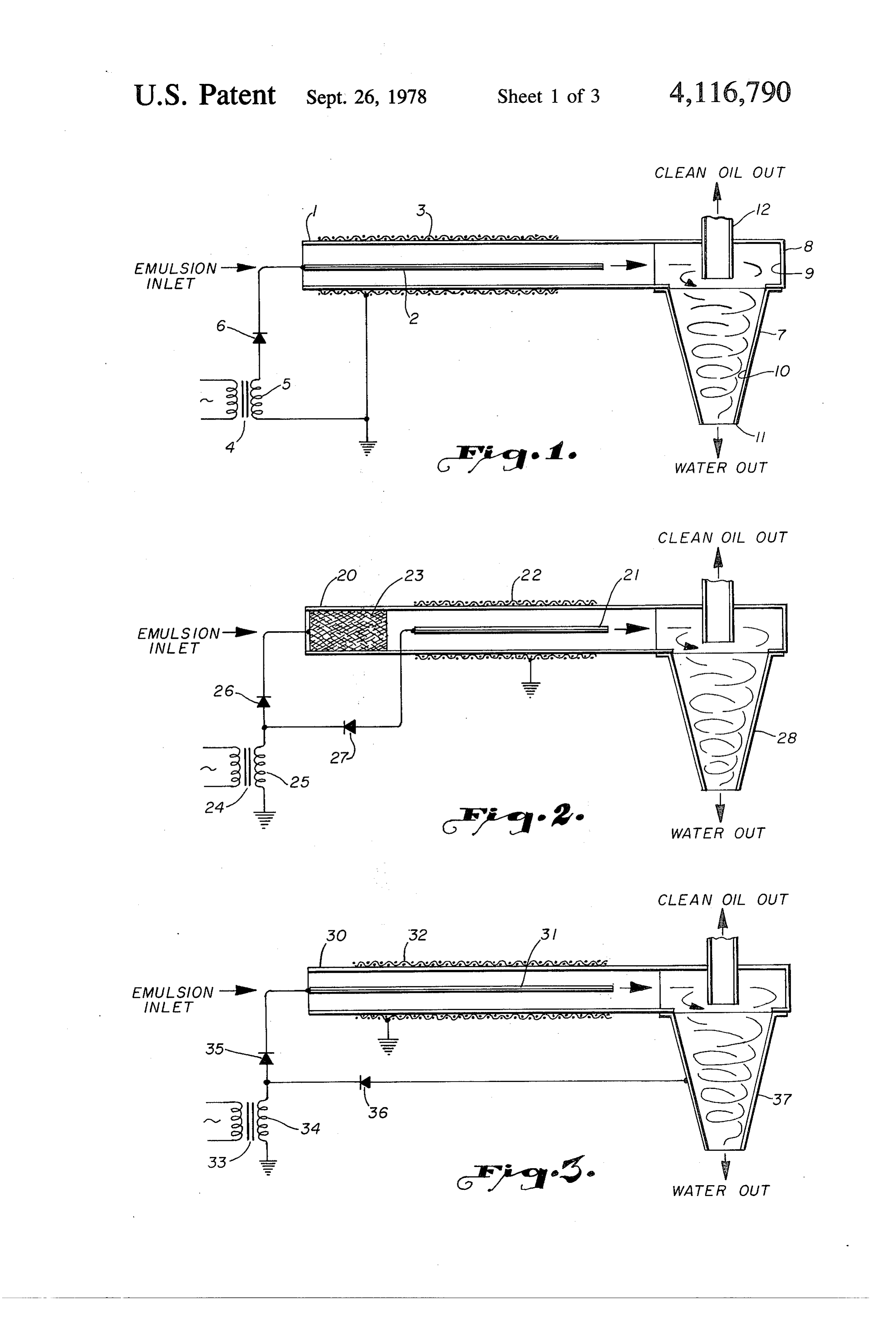
An electric field is a tool which has been used to in BRIEF DESCRIPTION OF THE DRAWINGS crease the size of the dispersed drops by forcing sepa FIG. 1 is a sectioned elevation of a somewhat dia rated drops to join each other, or coalesce. The increase grammatic showing of an electric field coalescer and in the falling velocity of the coalesced drops will enable centrifuge embodying the present invention;
the size of the retaining vessel required for retention FIG. 2 is similar to FIG. 1 but with a different electri time to be greatly reduced. ...,
Another tool in the separation art is the centrifuge. calFIG.
source for the coalescer;
3 is similar to FIG. 1 and with the outside wall
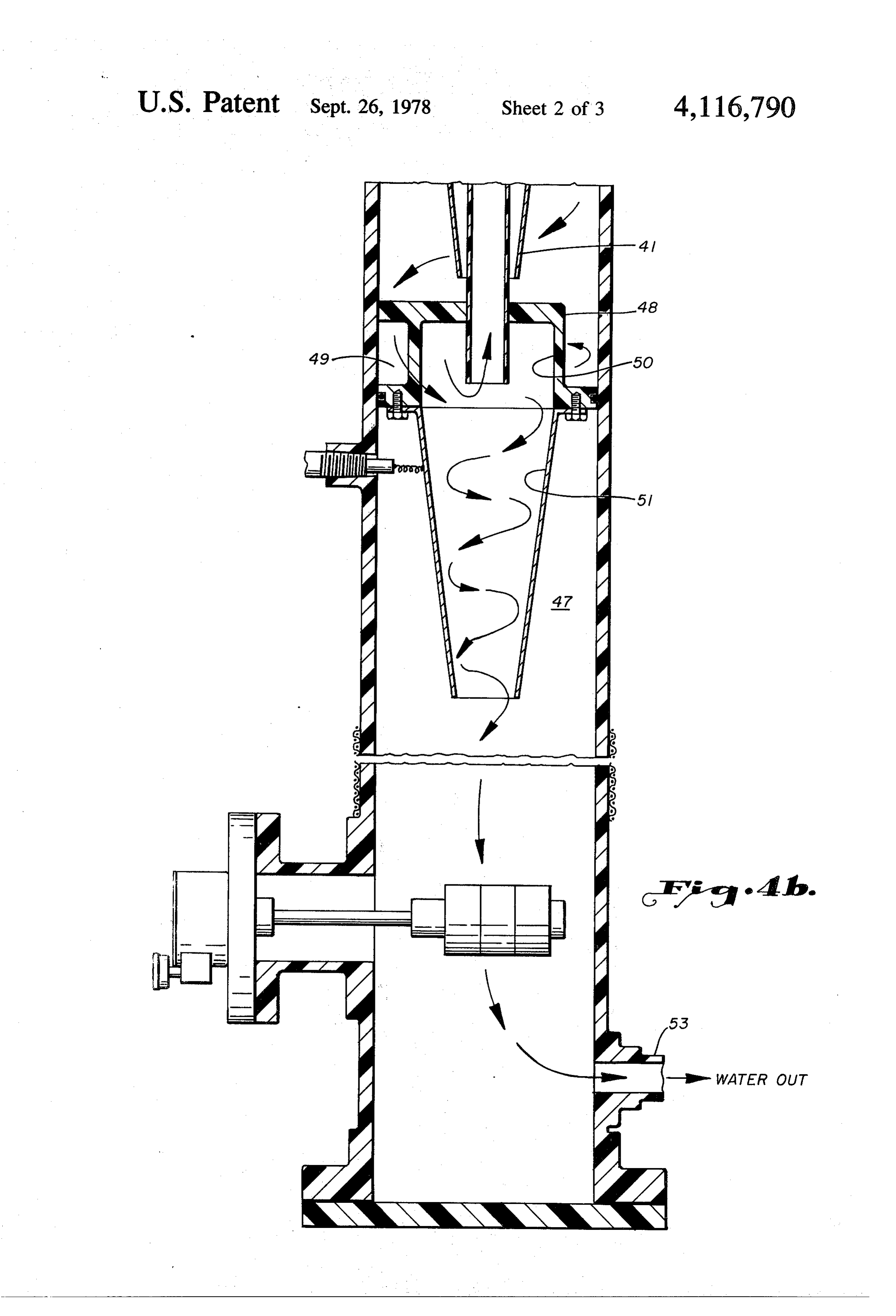
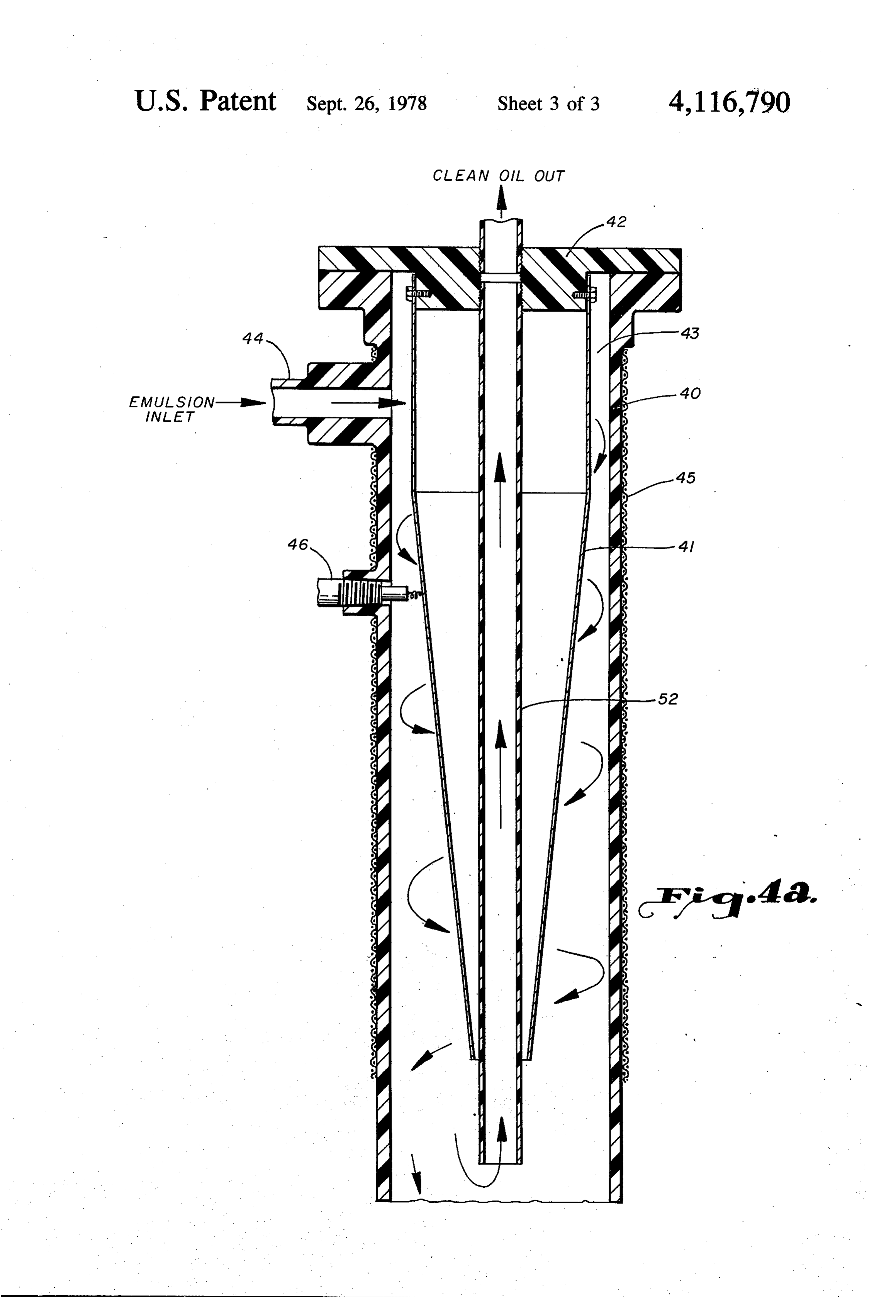
The centrifuge generates a force usually expressed in “G's,' G being the normal force of gravity. It is not 50 of the centrifuge included in the electrical circuit; unusual to develop the centrifugal force in a centrifuge FIG. 4 (on two sheets) is a somewhat diagrammatic to 1,000 G's in value. Many attempts have been made to sectioned elevation of a coalescer with divergent elec apply centrifugal force on the heavier fluid of a fluid trodes and a centrifuge in vertical orientation. mixture to separate it from the less dense fluids of the DESCRIPTION OF THE PREFERRED
Embodiment
The centrifuge has had varying degrees of success in separating gas from liquids, gas from solids and liquids At the outset of this description, an understanding on from solids. However, experience with liquid/liquid the terminology is desirable. Structuring definitions of separation has been frustrating. The oil-water mixtures the various facets of the inventive concepts in the dis of the oil field have met bewildering limitations in cen closure is difficult to couch in robust language within trifuge separation. this particular art. As novel as the concepts are, they are One of the reasons for the liquid/liquid separation embodied instructure and process which have had to be limitations with the centrifuge is that the difference in described with mundane words such as vessel, flow, densities of the liquids is not great enough. This is a fluids, coalescense, electrodes, and electric field. This is vague statement, of course. But a more important prob 65 hardly a dramatic arsenal from which to select telling lem can be stated more specifically. combinations that will ring with the solid advances this When the dispersed phase is very fine, that is, the invention makes in the art. Therefore, if I have not drops of dispersed liquid are down to the 2-5 micron words available with a persuasive bite to them, I wish to 6 at least make sure I am not misunderstood as I trace the completed by the time the mixture reaches the entrance periphery of the scope of the present invention. to centrifuge 7.
First, consider the term "fluid.' This term is to be Essentially, centrifuge 7 is in the form of a cone. A applied to material in both a gaseous as well as liquid chamber 8 is cylindrically shaped and mounted above state. This invention is not to be limited to its applica the cone 7. The conduit 1 is connected to the chamber tion to gaseous fluids or liquid fluids. However, the 8 to flow its fluid mixture tangential the internal wall fluids with which the invention was conceived, and surface 9. This direction, of course, imparts a circular reduced to practice, were produced oil and water of the motion to spin, to the fluids. The contained fluids are oil well and the fluids of liquid ion exchange systems in forced to flow downward upon the conical walls 10 of the mining industry. Therefore, without limitations, the 10 the centrifuge 7.
description will be based on the terminology of oil well The speed of the stream of fluids, and the dimensions production as it is processed to separation. of the chamber 8 and centrifuge, determine the magni Centrifugal force will be generated on the fluids. The tude of the centrifugal force generated on the rotating structure used to generate and apply this force has been spiralling fluids. It is not necessary to analyze the mag variously desribed. For the purposes of this disclosure, 15 nitude of these forces in disclosing this invention. It is the term "centrifuge' is used. This term applies to a sufficient to point out that the G's, G representing the structure in which a stream of fluids is directed into a value of gravity, can be many multiples if the differen spiral path. It could be used for the structure which is tial pressure across the centrifuge if established at a rotated from a source of power to develop force di large enough value by the dimensions of the centrifuge rected outwardly from the axis of rotation on fluids 20 and the volume of the fluid through-put. contained by the structure. However the structure de In all events, or rather, in all ranges of centrifugal velops and applies its centrifugal force to contained force values, forces which shear the separating fluids fluids, the structure will be taken as lending itself to the drops must be avoided. Sufficient centrifugal force must descriptive term "centrifuge,” an essential element in be placed upon the liquid mixture to physically move the invention. 25 the coalesced drops of dispersed liquid to the wall 10 The first three drawing figures are similar in disclos without the generation of shear force between the drops ing a combination of structure with which to generate and the entraining liquid which will refragment the an electric field and apply the field to a flowing stream drops.
of fluid and a centrifuge. In each Figure the circuit If this technological tightwire is successfully walked, connected to the electrodes and centrifuge is different 30 the drops of dispersed liquid, perhaps in the order of 2-5 from the remaining Figures. However, in all the Figures microns in size, will be staged up to the 8-10 micron size an electric field is generated by a source connected to range by the electric field and then forced into contin electrodes and a mixture of fluids passed through the ued agglomeration upon the internal wall of the centri field. The fluid is dispersed in the form of drops takes on fuge. Then the formerly dispersed fluid, coating the a charge which results in coalescense of the drops. The 35 wall 10, will flow downward and exit the centrifuge 7 at mixture is then passed into a centrifuge in which the exit 11.
drops of dispersed fluid, enlarged by coalescense, are Where does this leave the lighter, or less dense, of the forced toward the inner wall of the centrifuge. The fluids of the mixture? In the center of the conical cham separation of dispersed fluid from the other fluid within ber of the centrifuge. The heavier fluid was thrown into the housing of the centrifuge enables the fluid to be a layer on wall 10. The lighter fluid was left near the withdrawn at different positions for the final separation axis of the centrifuge. Conduit 12 is extended down into sought as the end result of the invention. the center of chamber 8 to provide an exit for the lighter More specifically, FIG. 1 discloses a conduit 1 in fluids that were left at the center of centrifuge 7. Sepa which an electrode 2 in rod-like form is axially ration is completed between the coalesced drops of fluid mounted. A conductive screen 3 is mounted as a sheath 45 which would accept the charge of the electric field in along a substantial length of conduit 1. A source of conduit 1 and the remaining fluids of the mixture at the electrical energy is supplied to these two electrodes and axis of the chamber 8 and centrifuge 7. an electric field is thereby generated between the elec The circuit of FIG. 1 supplies a simple D.C. voltage trodes. to the electrodes 2, 3. In FIG. 2, an apparently more Fluid passed into and along circuit 1 is within the 50 effective circuit is disclosed with the same general com electric field. If the fluid is a mixture of immiscible bination of coalescing structure and centrifuge, screen fluids, one of the fluids finely dispersed throughout the 22 is placed opposite rod-electrode 21 and on the out other fluids being in the form of drops which will ac side of conduit 20. A third electrode 23 is in the form of cept a charge, agglomeration of the drops will take a mesh of conductive material at the entrance to conduit place. There is no purpose served by redefining the 55 20. The fluid mixture forced into conduit 20 will pass mechanism of coalescense in this disclosure. The system through this mesh electrode 23 with intimate contact is generally well known in the art. and opportunity for the dispersed drops of fluid to take A transformer 4 is supplied from a source not shown. on the charge of the electrode.
One side of secondary 5 is connected in parallel to . The circuit connected to the three electrodes is dis ground and the screen 3. The second side of the second closed in U.S. patent, Prestridge U.S. Pat. No. ary is connected to rod electrode 2 through a rectifier 6. 3,772,180, issued Nov. 13, 1973. Transformer 24 has one This simple circuit between the source of electrical end of its primary 25 connected in parallel to mesh energy and the electrodes generates an electric field in electrode 23 and rod electrode 21 through rectifiers 26, conduit 1. A fluid mixture, in which finely dispersed 27. The second end of the primary 25 is connected to drops of a first fluid, is passed down conduit 1. The 65 ground. The third electrode, conductive sheath 22, is dispersed drops accept a charge and begin to coalesce. also connected to ground.
Dependent upon many factors which determine the The disclosed circuit applies a positive charge to mobility of the dispersed drops, some coalescense is mesh electrode 23 and a negative charge to rod elec 7 trode 21. Therefore, the difference between these two driving the centrifuge, or flowing through the centri establishes a relatively high intensity electric field. The fuge, fast enough to begin the coalescense of the water positive charge accepted by the dispersed drops in pass drops and refragmenting the drops against the barrier of ing through mesh electrode 23 generates a relatively fluid shear forces. It has been a bewildering and frustrat intense force driving the drops into coalescense. ing cycle of frantically searching for the centrifugal Compatible with the function of the systems dis speed which would wring out the dispersed lighter fluid closed in U.S. Pat. No. 3,772,180, the disclosed system from the entraining heavier fluid. Apparently the an of FIG. 2 provides two types of electrical fields togen swer of bringing the dispersed drop up to a size which erate coalescing forces on the fluid mixture passing could be effectively enlarged by carefully applied cen through conduit 20. It can be stated that the coalescense 10 trifugal force was not conceived in the prior art. Cer is carried out in stages before the mixture reaches the tainly, initial electrical coalescense, at the entrance to centrifuge. the centrifuge, was not discovered prior to this inven In all events, the coalescing action of the electric tion.
field, or fields, in conduit 20 enlarges the dispersed The disclosure now launches into a more sophisti drops to a size where the centrifugal force of centrifuge 15 cated application of the concepts of the invention. FIG. 28 can effectively take over and complete the separa 4 is divided between two sheets of drawing, one being tion. The function of centrifuge 28 is expected to be designated 4a and the second 4b. Together, FIGS. 4a essentially the function of centrifuge 7 in FIG. 1. and 4b depict a vertical form of electric coalescing At this point in the disclosure it is developed that the section on top of a centrifuge section, both mounted on electric field can be given several variations with differ 20 top of a heavier fluid discharge compartment. ent results. FIG.3 shows still another variation which is In FIG. 4a conduit housing 40 is extended vertically. even more effective, or efficient, than the arrangements Conical electrode 41 is supported from a closure mem of FIGS. 1 and 2. ber 42. Fluids are flowed into the annulus 43 between If the dispersed drops, coalesced in the electric field, the inner wall of housing 40 and the outer wall of elec bear a charge of one polarity, the internal wall of the 25 trode 41 through inlet 44.
centrifuge can be given an opposite charge and the Sheath electrode 45 is placed on the outside of con dispersed drops attached to the charged wall. FIG. 3 duit housing 40. The fluid mixture processed, conduit discloses the simple structure required to embody this housing 40, center electrode 41 and sheath electrode 45 concept. form the same general relationship these comparable In FIG. 3, conduit 30 has its center electrode 31 and 30 elements form in FIGS. 1, 2 and 3. An electric field is sheath electrode 32 in structural relationship similar to formed between the electrodes and in the annulus that of FIGS. 1 and 2. Further, transformer 33 has its through which the fluid mixture is passed. Coalescense primary 34 connected to rectifiers 35 and 36 similar to of conductive fluid drops dispersed in the remaining the FIG. 2 circuit. However, the positive connection is fluids of the mixture takes place as in the structure dis now to rod electrode 31 and the negative charge is 35 closed in FIGS. 1, 2 and 3. However, there is a differ applied to the wall of centrifuge 37. ence in the distribution of strength of the electric field This circuit arrangement of FIG. 3 provides a high which has advantages.
potential difference between electrode 31 and the wall The voltage gradient of the electric field decreases as of centrifuge 37. As the dispersed, and coalescing, drops the fluid mixture flows downward in conduit housing in the fluid mixture are charged by electrode 31 in con 40. This voltage gradient is established by the fact that duit 30, there will be a high potential between these electrode 45 and electrode 41 physically diverge from drops, as the mixture enters the centrifuge 37, and the each other in the downward direction of fluid mixture wall of the centrifuge. The result will be an added force flow within conduit housing 40. This decrease in volt directed to drawing the coalesced and positively age gradient has certain advantages.
charged drops to the wall. These expectations were 45 Again, the force applied to physically move dispersed actually realized in a reduction to practice, lifting the drops within entraining fluid is considered. The drops theory from speculation toward reality. The actual move if placed in an electric field. The speed with reduction to practice was an important step in progres which the drops move is dependent upon several fac sive development of the invention. tors. However, the voltage gradient of the field is a A pause is made to reflect on the fluid mixture pro 50 primary factor. If the drops are small (2-5 microns), the cessed in the reductions to practice of the invention. Oil voltage gradient required to significantly coalesce must and water mixtures were processed in the structure be so great that as the drop enlarge toward the 8-10 depicted in FIGS. 1, 2 and 3. It was the water which micron range the force of the field move the drops so was dispersed in very small-sized drops in the oil. It was rapidly that fluid shear forces between the drops and the water drops which readily accepted the positive 55 the fluid in which the drops are dispersed is great charge and coalesced in the electric field. The drops of enough to refragment the enlarging drops. Therefore, water were so fine, or small, that they were in the order some way of backing away from the voltage gradient of of 2-5 microns in diameter. Only the electric field the electric field is very desirable. The divergent elec proved effective to move these drops in the dance of trodes is one way to establish the decreasing voltage coalescense, bringing them up at least as far as the 8-10 60 gradient.
micron range at which the centrifugal force could be The electric network to energize the conical elec applied to move them toward unification without gen trode 41 and sheath electrode 45 is not disclosed in FIG. erating the dreaded magnitudes of the liquid shear force 4. Enough of network disclosure was disclosed in between the oil and the enlarging drops of water. FIGS. 1-3. Here, in FIG. 4a, electrode 41 is shown as This operation of the centrifuge on drops of water 65 suspended from insulator-closure 42 and electrically required a great deal less power for operating the cen connected to a network outside housing 40 with con trifuge than prior attempts to move the smaller drop nector 46. An electrical connection to sheath 45 does sizes. The art apparently accepted the limitation of not seem necessary.
Page 8scan →
The coalescing fluid mixture spirals down annulus 43 FIG. 4a and 4b there is added the decreasing gradient and is conducted into centrifuge 47 which is mounted field to avoid refragmentation of the enlarging drops below conical electrode. Centrifuge 47 receives all of and the vertical orientation of all the structure to add the discharge from the coalescing section above it. The the component of gravity to draw the coalesced drops dispersed fluid drops are coalesced to the size where the 5 of fluid downward while the remaining fluid is drawn centrifugal force applied to them will move the drops to upward in the final separation.
the internal wall of the centrifuge without shearing o These concepts of fluid separation have been applied fragmenting the drops. with great advantage to liquid/liquid separation in par To direct the fluid mixture into the centrifuge 47, a ticular. Even more specifically, the invention has been cylindrical chamber 48 is mounted below electrode 41 10 reduced to practice with oil/water as the fluids to be and across the conduit housing 40. A passage 49 is separated, the water being dispersed in the oil as very formed to function as a tangential entrance to the inte small drops. There are many other liquid/liquid separa rior of chamber 48. The fluids, flowing tangentially, tion problems. The solvent extraction systems of the against the interior wall of chamber 48, develop a cen mining art are good examples. Wherever a fluid, which trifugal force on the more dense, and enlarging, drops 15 will accept a charge, is finely dispersed in a so-called of coalesced fluid which moves them to form a coating continuous phase of a second fluid, the present inven on the interior wall 50. tion can be used.
Of course the size of the chamber, and that of the From the foregoing, it will be seen that this invention fluid stream, must be set to develop only enough force is one well adapted to attain all of the ends and objects on the dispersed drops which will effectively move 20 hereinabove set forth, together with other advantages them but will not shear, or fragment, them. Once the which are obvious and inherent to the method and ap drops are staged up to an enlarged predetermined size paratus.
by the electric field, such design is not an unreasonable It will be understood that certain features and sub goal. The stream of fluids continue to spiral down the combinations are of utility and may be employed with inside wall 51 of the centrifuge, the dispersed fluid 25 out reference to other features and subcombinations. forced toward the wall 51 and the remaining, lighter, This is contemplated by and is within the scope of the fluids being left in the center of the centrifuge. invention.
Separation is now possible. A conduit 52 is extended As many possible embodiments may be made of the down the axis of the conduit 40. Conduit 40 is extended invention without departing from the scope thereof, it is through the upper closure member 42, down through 30 to be understood that all matter herein set forth or conical electrode 41 and through the top of the upper shown in the accompanying drawings is to be inter cover of chamber 48. The lighter fluids of the centri preted in an illustrative and not in a limiting sense. fuged mixture will then flow up conduit 52 for final, The invention having been described, what is claimed positive, separation from the heavier, coalesced, drops 1S of fluid forced to wall 51. 35 1. A process for separating a first fluid which is finely An additional force applied to the dispersed drops of dispersed in a second fluid, including, fluid is provided in the cone of centrifuge 47. An elec flowing the first and second fluids as a mixture of tric potential is applied to the centrifuge which is of a immiscible fluids in a path, polarity opposite to that accepted by the dispersed establishing an electric field in the path to coalesce drops. With this arrangement, an additional force is the dispersed fluid into drops of predetermined placed upon the dispersed drops of fluid, moving the S1ze, t drops to the internal wall 51 of the centrifuge 47. The flowing all the mixture in a second path, electrical connection 52 is disclosed as through the wall and generating a predetermined centrifugal force on of the conduit 40 to the wall of centrifuge 47. This is the all the mixture in the second path to cause the means with which the charge on the centrifuge wall is 45 coalesced drops to agglomerate without re-disper played from a source not shown. sion into the second fluid and separate from the The coalesced fluid drops, forced into a layer of second fluid.
dense fluid on wall 51, discharges from the lower end of 2. The process of claim 1, including, centrifuge 47 and travels to the bottom of conduit 40. A establishing a potential between the coalesced drops conduit 53 is shown as providing passage from chamber 50 and a point within the mixture of fluids to supple 40 for the dense fluid which were coalesced and centri ment the centrifugal force on the coalesced drops fuged from the remaining lighter fluids. to cause the drops to agglomerate and separate Arranging the coalescing structure and centrifuge is a from the second fluid.
vertical orientation provided the supplemental assist 3. The process of claim 1, including, ance of gravity in separating the fluids. The heavier, 55 flowing the fluid mixture downward in its path more dense, fluids are always being pulled down and through the electric field and centrifugal force to away from the lighter fluids which are pulled up and provide gravitational force upon the coalesced out of conduit 52. The force of gravity, the pull of the drops as a supplement to bring about separation of electric field and the tug of the centrifugal force of the the fluids of the mixture. centrifuge combine to tear the drops of dispersed 60 4. The process of claim 1 in which the first fluid is a heavier fluid from the remainder of the mixture of fluids liquid in the form of finely dispersed drops and the to bring about their final, positive separation from each second liquid has the drops of the first liquid dispersed other. in it.
All of the concepts embodied in the structure of 5. The process of claim 4 in which the first liquid is FIGS. 1, 2 and 3 are found in FIG. 4a and 4b. The 65 water and the second liquid is oil.
electrical coalescense, the centrifugal force on the en 6. The process of claim 1 in which the first fluid is larged drops and the electrical attraction of the en more dense and heavy than the second liquid and will larged drops to the internal wall of the centrifuge. In accept a charge more readily than the second liquid.
Page 9scan →
9 O 7. A process for separating a first fluid which is finely cessed by the electric field and centrifuge, whereby dispersed in a second fluid, including, the force of gravity acts downward on the co flowing the first and second fluids as a mixture of alesced and centrifuged drops to further their sepa immiscible fluids in a path, ration from the remaining fluids of the mixture. establishing an electric field with a finite strength at a 5 11. The processor of claim 9 wherein, point upstream of the fluid mixture in the path and the electrodes are mounted in the first vessel and on a strength which decreases along a downstream each side of the flow path so as to be spaced a finite distance from the upstream point to coalesce the distance from each other at a point in the path and first dispersed fluid into drops of predetermined diverged from each other in the downstream direc S1ze, O tion of the flow path.
flowing the mixture in a second path, 12. The processor of claim 8 in which the first fluid is and generating a predetermined centrifugal force on a liquid in the form of finely dispersed drops and the the mixture in the second path to move the drops second fluid is a liquid in which the drops of the first coalesced by the electric field and cause the co fluid are dispersed.
alesced drops to agglomerate without redispersion 15 13. The processor of claim 12 in which the first liquid in the second fluid and separate from the second is more dense and heavy than the second liquid and will fluid. accept a charge more readily than the second liquid. 8. An electric-centrifugal processor for mixtures of 14. The processor of claim 13 in which the first liquid multiple fluids, including, is water and the second liquid is oil. a first vessel, 15. An electric-centrifugal processor for mixtures of a source of a mixture of multiple fluids, multiple fluids, including, a flow path formed for the mixture within the first a first vessel, vessel, a source of a mixture of multiple immiscible fluids electrodes mounted within the first vessel and on each side of the flow path, 25 including a first fluid finely dispersed in a second a source of electric energy connected to the elec fluid, trodes with which an electric field is established by a flow path formed for the mixture within the first the electrodes so that the fluid mixture flows in the vessel, field while flowing down the path to coalesce one electrodes mounted within the first vessel and on of the fluids into drops of predetermined size 30 each side of the flow path, within another of the fluids, a source of electric energy connected to the elec a second vessel connected to the first vessel so as to trodes with which an electric field is established by receive the entire fluid mixture from the path of the the electrodes so that the fluid mixture flows in the first vessel, field while flowing down the path, to coalesce first and means within the second vessel for developing a 35 fluid drops into drops of predetermined size, predetermined centrifugal force on the entire fluid a second vessel connected to the first vessel so as to mixture received from the first vessel to move the receive the entire fluid mixture from the path of the coalesced drops of the one of the fluids into an first vessel,' agglomeration separate from the other of the fluids a centrifuge mounted within the second vessel so as without redispersion of the one fluid into the other to develop a predetermined centrifugal force on fluid. the entire fluid mixture by flowing the mixture 9. The processor of claim 8 in which, tangential to the internal wall of the centrifuge, the the second vessel and means comprise a centrifuge predetermined centrifugal force moving the co which is connected to receive all of the fluid mix alesced first fluid drops into a layer on the internal ture from the first vessel and flow the mixture 45 wall without redispersion into the second fluid to tangential to the internal wall, the predetermined flow to separation from the remaining fluids of the centrifugal force thereby generated on the fluid mixture, mixture forcing the coalesced drops into a layer on and means for maintaining a charge on the internal the internal wall without redispersion and from wall of the centrifuge opposite to the charge ac which the agglomerated fluid flows to separation 50 cepted by the coalesced drops of the first fluid, from the remaining fluids of the mixture. whereby the charge generates a force on the drops 10. The processor of claim 9 in which, which aids the centrifugal force in bringing the the vessels of the processor are arranged and aligned drops to the wall of the centrifuge. vertically so the fluids flow downward while pro
Provenance
- Collection
- Patents citing this work
- Pages
- 9
- Method
- pdftotext (the PDF's own text layer) + pdftoppm 300dpi page scans
- Patent office record
- patents.google.com →
- Source
- Google Patents citing-documents table
- Assignee
- Combustion Engineering, Inc.
- Published
- 1978-09-26
- Transcribed from
- patentimages.storage.googleapis.com →