

patent · US4117829A
Fur-like photothermal converter surface
3 October 1978
Text
Page 1bibliographic recordscan →
United States Patent (19)
Gross et al.
54 FUR-LIKE PHOTOTHERMAL CONVERTER
SURFACE
75 Inventors: Daniel Gross, Carouge, Geneva;
Pierre Genequand, Geneva, both of
Switzerland 73 Assignee: Battelle Development Corporation,
Columbus, Ohio
(30) Foreign Application Priority Data
Jan. 8, 1976 Switzerland ........................... 156/76 Int. C.’................................................. F24J 3/02 52 U.S. Cl. .................................... 126/270; 126/271;
Field of Search ....................... 126/270, 271, 400;
2,998,006 8/1961 Johnston .............................. 126/271 3,194,228 7/1965 Bangues ................ ... 26/27 3,229,682 1/1966 Permutter et al. .... ... 126/270 3,379,394 4/1968 Bialy ..... ... 126/270 3,780,722 12/1973 Swet. ... 126/270 3,902,474 9/1975 Pyle ........... ... 126/270 3,985,116 10/1976 Kapany ............. ... 26/270 4,005,698 2/1977 Cuomo et al. ....................... 126/270
4,038,964 8/1977 Drew ................................... 126/271
FOREIGN PATENT DOCUMENTS
1,576,354 6/1969 France ..................................... 126/270 Primary Examiner-John J. Camby
Assistant Examiner-Henry C. Yuen
Attorney, Agent, or Firm-Thomas W. Winland
In order to reduce energy losses by convection and/or thermal radiation from the radiation-absorbing surface of a photothermal energy converter for the utilization of solar energy, the said surface is provided with a multiplicity of projecting fibres sufficiently close to one another to suppress convection, each fibre consisting of a material which is permeable to the incident luminous radiation to be absorbed and at least partly opaque to infrared thermal radiation which may be reemitted from the said surface whereby energy losses by radiation are reduced.
The fibres can be, for example, glass or plastic fibres and can be integral with or implanted in the said surface. Preferably, the fibres have diameters in the range 25 to 500 micrometers, a height of the order of 5 cm, and an average distance between fibres in the range 100 to 5000 micrometers.
26 Claims, 16 Drawing Figures
Drawings
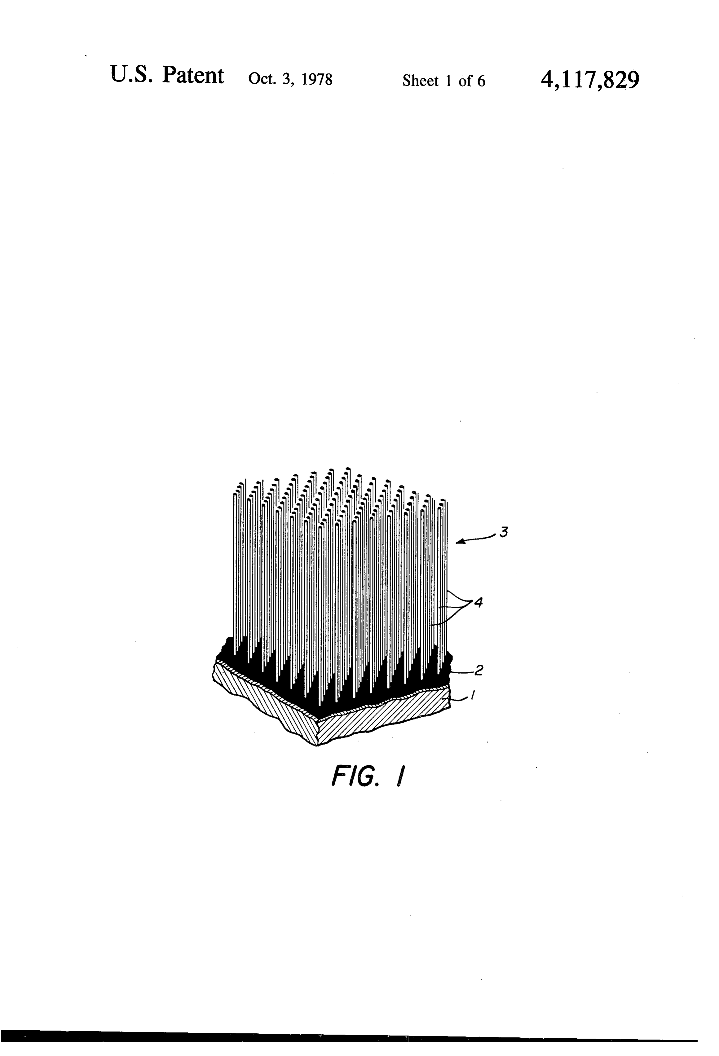
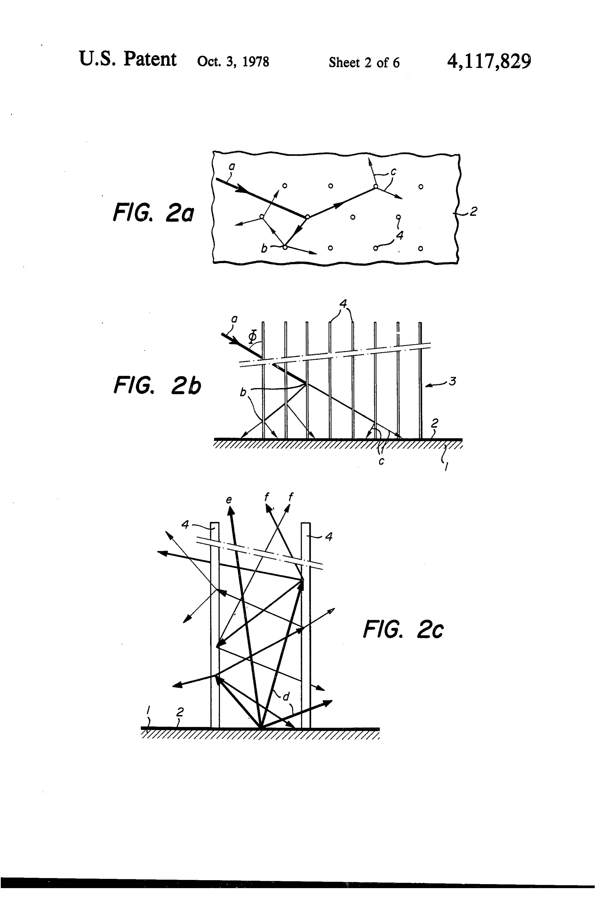
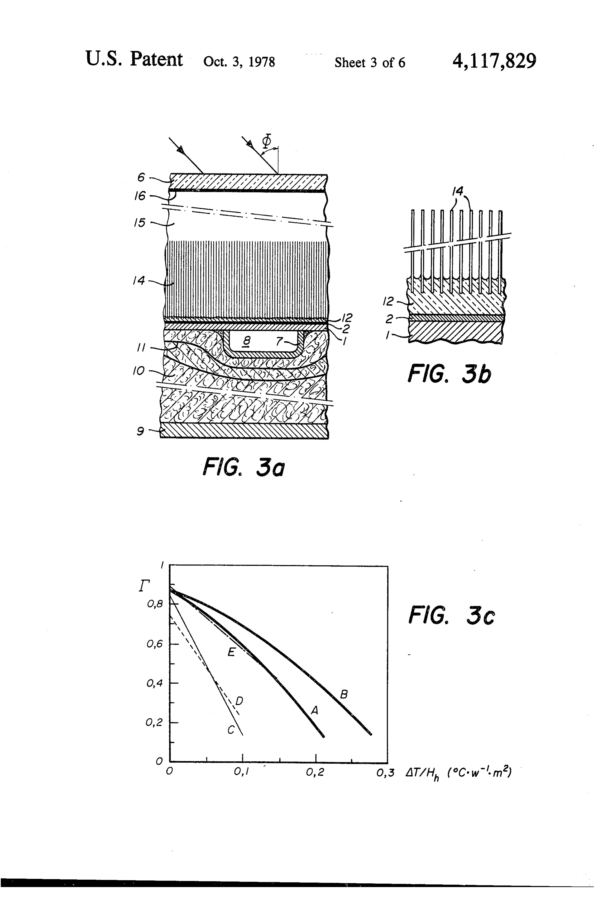
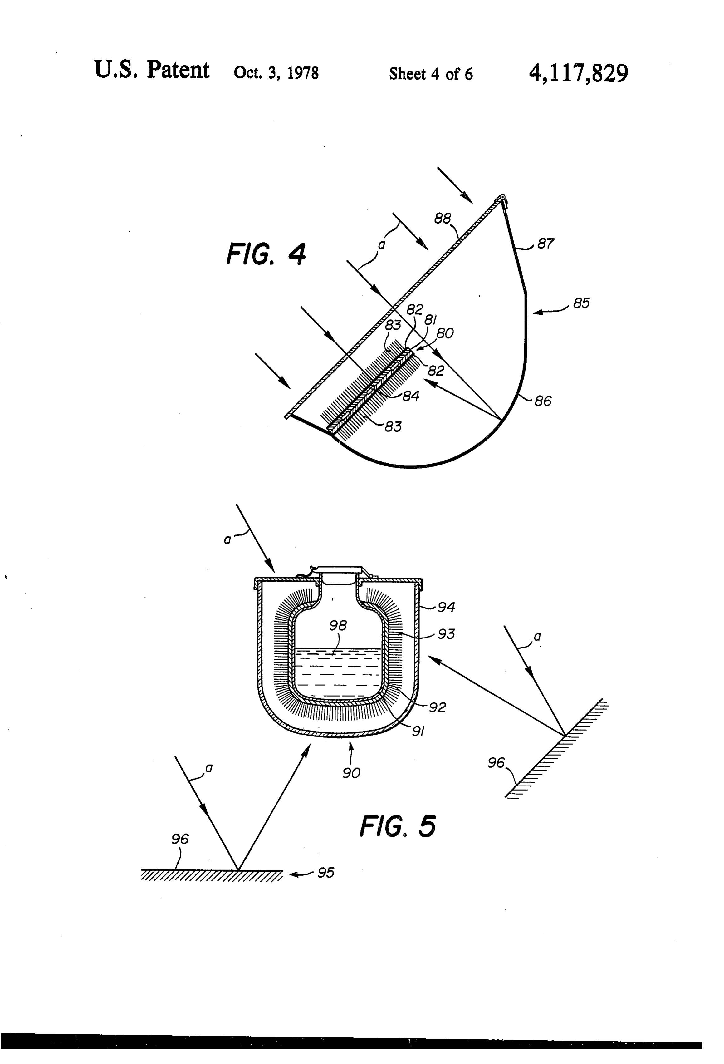
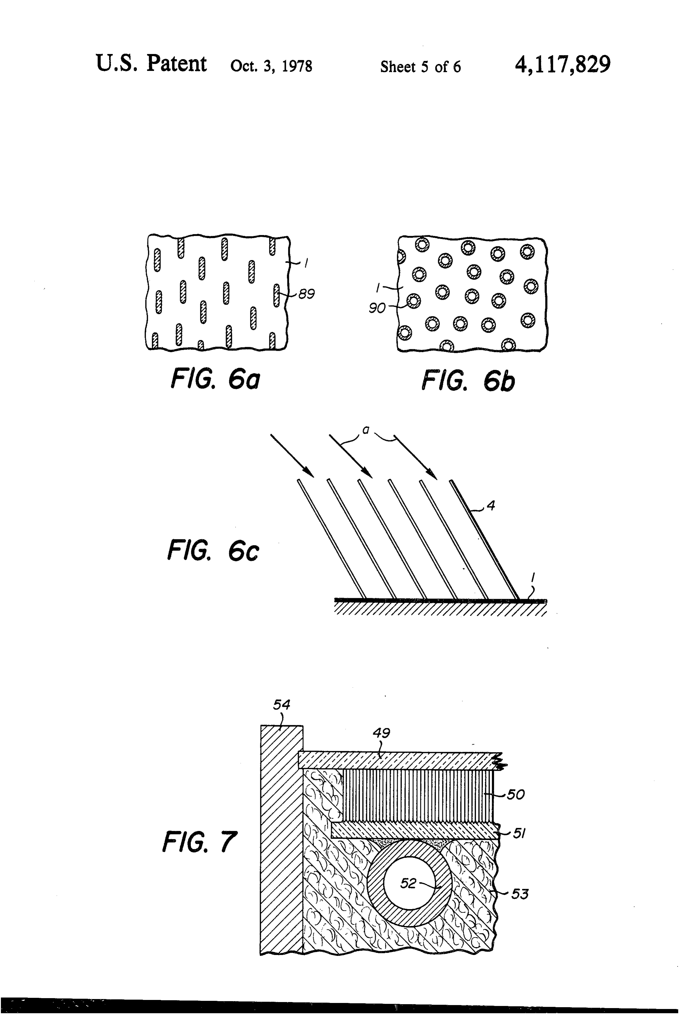
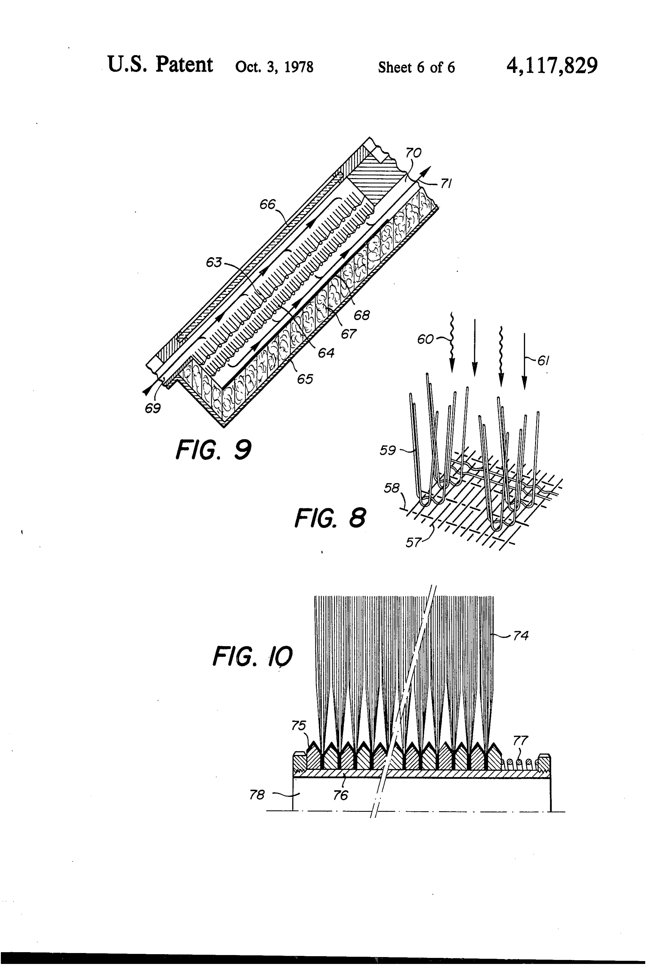
FIG. 8 is a perspective view showing another em reactive gas etc.), or loads (i.e. immobile bodies placed bodiment.
Page 2drawing sheetscan →
Page 3drawing sheetscan →
Page 4drawing sheetscan →
Page 5drawing sheetscan →
Page 6drawing sheetscan →
Page 7drawing sheetscan →
Page 8scan →
jected to considerable thermal cycles (variations in the
FUR-LIKE PHOTOTHERMAL CONVERTER pressure of the thermal insulation gas) and to other SURFACE atmospheric attack, undermining in particular its air
Background
tightness. Finally, in the particular case of application to solar collectors, the appearance of any crack in the
In the field of utilization of solar energy, the photo covering glass (hail, falling branch, thrown stones ...) thermal conversion process is of prime importance. has the inevitable effect of making these collectors un This process enables for example thermal energy to be workable by causing escape of the low thermal conduc produced for domestic heating or air conditioning, and tivity gas.
enables hot water (pressurized) or steam to be obtained 10 For collecting the solar energy it has also been pro for the production of mechanical energy or for various posed to use a honeycomb structure resting on a con other industrial processes etc. Photothermal conversion ventional absorbing surface. This structure is preferably may be defined as the absorption of an incident electro made of fine glass plates or tubes, which may typically magnetic radiation (such as solar radiation) by an absor have a height of 6 to 25 cm, a diameter of 0.5 to 1.5 cm bent collecting surface, with subsequent heating of this 15 and a thickness of 0.2 to 0.3 mm. Such a structure has collecting surface, which in its turn heats a determined the advantage of serving as a light guide for the incident heat exchanger fluid or load. In general one seeks to solar radiation, which undergoes a multiplicity of re obtain the highest possible operating temperature for a flections and refractions before being absorbed by the given incident radiation power per unit of converter actual converter. Where the height-diameter ratio is surface (the intensity of solar radiation is notably limited 20 sufficiently high, such a structure may also serve as a and depends also on the hour of the day, the meteoro thermal barrier for the re-emitted infrared radiation, logical conditions etc. With regard to direct solar radia which is compelled to follow a diffusion process before tion, optical concentration may be used by means of being able to reach the exterior, with consequent reduc collecting mirror or lens systems). To obtain a high tion in radiation losses. However, such a structure does operating temperature, effective thermal insulation of 25 not give optimum reduction in convective air move the two faces of the converter is necessary in addition to ments, especially where there is a large temperature high incident radiation intensity. Thermal insulation of difference between the converter and its immediate the face exposed to the incident radiation however is surroundings, and/or where the converter is inclined. difficult to effect, because this face has at one and the In this respect, a limiting air layer of small thickness same time to absorb the incident radiation and refrain 30 (about 1 mm) and of unstable buoyancy notably forms from emitting thermal infrared, so that it must be made above a horizontal heated surface, and convective fila absorbent with regard to incident radiation and reflect ment-type movements develop from this limiting layer ing with regard to emitted radiation. which mix by convection with the air layers situated In any photothermal converter, three well known further above the hot surface. It is equally known that thermal loss processes must be considered: losses by 35 this instability, in the case of an inclined cellular struc thermal infrared radiation omission, cooling by convec ture, takes the form of regular circulation within each tion to the interior of the gaseous volume separating the cell.
converter from its immediate surroundings, and losses As these constituent cells of the honeycomb structure by thermal conduction. have lateral dimensions which are considerably greater In recent years numerous methods have been pro than the characteristic diameter of these filament-type posed for minimizing the total of said thermal losses, convective movements (or than the thickness of the and consequently increasing the photothermal conver movements assuming the form of a regular circulation sion efficiency. To reduce radiation losses it has been ratio greater than 2), it follows that such a structure is proposed for example to use surfaces which are selec not capable of suppressing the convective air move tive to radiation. These surfaces, of low thermal emis 45 ments in an optimum manner, and consequently pre sivity, in particular allow practically complete absorp venting the cooling of the converter by convection. tion of the incident solar radiation, while strongly re Moreover, this honeycomb structure is relatively thick, ducing losses by infrared radiation from the converter. given the height (6 to 25 cm) of the cells, so that a solar However, the presence of such surfaces contributes to collector equipped with such a structure risks being too strongly increasing the cost of the converters, and poses SO heavy and too bulky for the majority of applications. long term stability problems. Three main methods are The need to use a considerable quantity of glass for this known for reducing convection losses. The first consists structure (of the order of 12 to 60 kg/m of converter) of stacking several transparent cover plates above the further leads to a total weight and prices which are converter so as to confine the convection mechanism to hardly competitive. Moreover, this large mass of glass within volumes of lower temperature differences. How 55 gives rise to very high thermal time constants, so that ever this plate stacking contributes to increasing losses one or several hours of continuous exposure to solar by reflection of the incident radiation, and results in an radiation are necessary before such a collector attains its increase of the weight and cost of the device. The sec working temperature.
ond method consists of filling the space above the con The object of the present invention is to remedy the verter with a gas having a thermal conductivity lower various aforementioned disadvantages, by proposing a than air, while the third method consists of completely photothermal converter of high conversion efficiency evacuating this air space. However the second method and economical cost.
enables only a partial reduction of the conduction/con SUMMARY vection losses to be obtained. The third method tends to be costly, as it requires the presence of absolutely air 65 The present invention provides a photothermal con tight enclosures which have a low degassing rate. The Verter comprising a surface of which at least one of the construction of long life airtight enclosures is moreover faces, intended for exposure to an incident luminous difficult, bearing in mind that these enclosures are sub radiation, is endowed with strong absorbent power in 9 respect of this radiation, and further comprising a multi DRAWINGS plicity of projecting fibres on said face extending sub stantially parallel and substantially equidistant to each FIG. 1 is a partial perspective view showing a first other, each fibre consisting of a material which is both embodiment of the converter according to the inven permeable to said luminous radiation and at least par tion.
tially opaque to the infrared thermal radiation which FIG. 2a is a partial view from above of FIG. 1 to a may be re-emitted by said surface, said multiplicity of ray larger scale, showing the path of an incident luminous fibres thus constituting an antiradiation and anticonvec through the front part of the converter. FIG, 2b is a partial longitudinal diagrammatic sec tion structure which on the one hand enables the losses 10 tional view of FIG. 1 to a larger scale, also showing the by infrared thermal radiation to be reduced, and on the path of the incident ray.
other hand enables convection losses to be suppressed. FIG, 2c is a sectional view analogous to that of FIG. In the present specification, the term "incident lumi 2b but to a still larger scale, showing the path of the nous radiation' signifies any electromagnetic radiation infrared thermal radiation re-emitted towards the front originating from a high temperature thermal source, i.e. 15 of the converter.
any electromagnetic radiation capable of conveying FIG. 3a is a partial longitudinal sectional view show considerable thermal energy, this radiation having a ing a first modification of the converter according to spectrum situated entirely or only partially in the visible the invention, incorporated in a flat solar collector. spectrum, or a spectrum situated completely outside the FIG, 3b is a view to a larger scale, showing a detail of visible spectrum. Advantageously, the spectrum of such 20 FIG. 3d.
radiation may lie between 0.25 and 5 um. The high sionFIG. 3c is a diagram relating to the energy conver efficiency of the collector of FIGS. 3a and 3b.
temperature thermal source able to emit such radiation FIG. 4 is a longitudinal sectional view showing a may be either a source of natural radiation such as the second modification of the converter according to the sun, or artificial sources of radiation such as bodies 25 invention, incorporated in a double exposure system. raised to incandescence (if possible placed under vac FIG. 5 is a longitudinal sectional view showing a uum to reduce losses), flames or gaseous discharges. third modification of the converter according to the In the present specification, the term "fibre' signifies invention, incorporated in a device intended for heating any filiform element of finite length, the cross-section of a load.
which remains small in relation to its length. Such an 30 FIG. 6a is a partial view from above analogous to element may be either solid or hollow, and either be of that of FIG. 2a, showing a fourth modification. circular or non-circular cross-section, for example ellip FIG. 6b is a view analogous to that of FIG. 6a, show tical or flat. ing a fifth modification.
The heating of the absorbent plate resulting from its FIG. 6c is a longitudinal sectional view analogous to exposure to the incident luminous radiation may be used 35 that of FIG, 2b, showing a sixth modification. advantageously in its turn in known manner, to heat FIG. 7 is a longitudinal section through a another either heat transfer fluids (such as water, steam, oil, air, embodiment
FIG. 8 is a perspective view showing another em reactive gas etc.), or loads (i.e. immobile bodies placed bodiment.
in the vicinity of the absorbent surface). FIG. 9 is a longitudinal section showing a conven The heating of a load by incident radiation acting by tional solar collector in which this embodiment is incor way of a converter in accordance with the invention porated.
may in effect present certain advantages over other FIG. 10 is a longitudinal section, showing another known methods of heating. It is possible firstly to place embodiment.
the load/converter assembly at a certain distance from 45 the radiation source. Such a possibility enables the load PREFERRED EMBODIMENTS to be disposed for example in a corrosive environment, The photothermal converter shown partially in FIG. under vacuum, in controlled magnetic or electrical 1 comprises a metal baseplate 1 covered with a layer 2 fields etc. Radiation heating is likewise a very suitable of a material endowed with strong absorption power for heating from the chemical and/or biological viewpoint 50 incident luminous radiation, and on which there is fixed (non-contamination). Radiation heating may also be a dense network of fibres 3 which extends substantially initiated, controlled and stopped more rapidly than over the whole surface of the plate 1. The network 3 is electrical resistance heating or flame heating, the two composed of a multiplicity of transparent fibres 4 of latter requiring fairly thick walls between the heating 55 substantially uniform length and substantially circular agent and the load. Radiation heating is also less costly section, fixed individually by one of their ends into the than microwave heating, for example. Examples of layer 2 and all oriented substantially perpendicularly to loads which may be heated by the converter according the plate 1, to remain spaced apart substantially by a uniform amount. The aforementioned network of fibres to the invention are chemical reactions for ultra-pure 3 is designed to perform various functions, as will be materials, constant temperature heating of microbiolog evident hereinafter. To be able to perform these func ical preparations, cooking or frying food (for example tiona, the network must possess two well defined the preparation of food dishes in casseroles or plates groups of characteristics, one of which relates to the equipped with a sealed photothermal converter). constituent material of the fibres and the other to the The accompanying drawings illustrate diagrammati geometrical dimensions of the fibre network. Thus, cally and by way of example several embodiments and 65 each of the fibres 4 must be made of a material which is modifications of the photothermal converter according both transparent (i.e. non-absorbent and non-diffusive in to the present invention, shown either alone or as part respect to the incident radiation, and opaque (i.e. of various devices. strongly absorbent and emissive in all directions) in 10 respect of infrared thermal radiation (the absorptivity fractions, so that it is reflected into a multitude of sec and thus the emissivity for intermediate wavelengths ondary beams (c), which all reach the absorbent surface being able to be adjusted in accordance with the opera 2 of the converter plate 1. All the secondary deflected tional temperature of the converter). beams (c) are in fact necessarily localized on cones the Advantageously, such a material must also possess axis of symmetry of which are constituted by the fibres, low thermal conductivity, and be chemically and struc these cones all intersecting the absorbent layer 2. Fur turally stable at the operating temperature of the con thermore, that portion of incident radiation trapped verter, and if possible as far as the "zero flow tempera inside the individual fibres (total reflection) is also com ture' of the converter. Finally, the material must have pelled to reach the base of the fibres. The individual such mechanical characteristics that the fibres possess 10 fibres 4 and the interstices existing between the fibres sufficient rigidity so as not to bend under their own thus act as a light guide for the incident radiation, what weight. ever the direction of this latter relative to the plate 1, so It is particularly preferred to use as the constituent compelling almost the whole of this radiation to strike material of the fibres, inorganic materials such as glass, the absorbent surface 2 of the converter plate 1. silica and possibly gypsum. Organic materials such as 15 The only optical losses which can be produced while Mylar or polyester may also be used. Likewise, for the passing through the fibre network are losses which may network to be able to perform the aforementioned func result from the process of absorption or diffusion by the tions, the geometrical dimensions of the fibre network fibres (absorption if the fibres are not completely trans must be within the following ranges: each of the constit parent, and diffusion if the fibres have a surface which uent fibres of the network must have a length of 1 to 10 20 is not completely smooth from an optical point of view cm and a diameter of 25 to 500 um, and the distance or if they have centers of diffusion within their volume). between the fibres of the network must be 100 to 5000 It should also be noted that only at the most one half of plm, with a fibre density (number of fibres per unit area the radiation thus absorbed or diffused emerges out of the baseplate) of 4 to 10000 fibres per cm. It is wards to give a true optical loss (optical loss by retrodif particularly preferred to use a network composed of 25 fusion outwards), the remainder, representing not less fibres with a length of the order of 5 cm and a diameter than half of this radiation, succeeding in reaching the of the order of 70 um, spaced apart so as to give a absorbent plate. It is further found that the retrodiffu density of the order of 500 fibres per cm and a sion optical losses increase with the angle of incidence volumetric density or filling percentage (proportional of the incident luminous radiation (angle between the to the quotient of the sum of the fibre cross-sections 30 radiation and the normal to the absorbent plate), but and the total surface of the baseplate) of less than 2%. these are always a minimum whatever this angle of The described converter operates in the following incidence. By way of example, it has been found that for manner when exposed to incident luminous radiation. a glass fibre network with 5 fibres/mm (network con The luminous radiation which strikes the absorbent sisting of glass fibres 5 cm high and 50 um diameter, layer 2 after traversing the transparent fibre network 3 35 obtained by drawing "Eglass'), a transmission factor is is continuously absorbed by the layer 2, so that the obtained for the incident luminous radiation through baseplate 1 heats up progressively under the effect of this network of about 99% for zero angle of incidence, this absorption, until it reaches its operating tempera about 97% for an angle of incidence of 45°, and about ture (temperature rapidly attained because of the low 95% for an angle of incidence of 60. To these optical thermal mass of the fibres 4). The heat so obtained may losses through the fibre network are added the optical then be transferred to a determined load or heat transfer losses due to incomplete absorption by the absorbent fluid, for various applications. plate. It is well known that these latter optical losses The purpose of the fibre network 3 is to reduce to a depend essentially on the nature of the constituent mate minimum the thermal losses outwards from the con rial of the layer and the state of the surface of the layer verter (which inevitably result from the heating of the 45 (rough or properly smooth). By way of example, it has absorbent plate), while allowing the best possible pene been found that an absorption factor of the order of tration of the incident luminous radiation to the absor 95% is obtained with an absorbent layer consisting of a bent plate (minimization of optical losses on penetra mixture of Scotch No. 582 adhesive and carbon black. tion). These different results are obtained because of the Considering the aforementioned optical losses, a total multiple functions performed by the fibre network 3, 50 optical conversion efficiency (product of the transmis which at one and the same time acts as a light guide for sion factor through the fibre network and the absorp the incident radiation, as a thermal barrier for the infration factor of the absorbent plate) of the order of 94% red thermal radiation re-emitted, and as an inhibiter for may thus be obtained. This optical conversion effi convective gas movements. ciency is independent of the temperature which may be These different functions will be examined in detail 55 reached by the converter.
hereinafter, together with the manner in which they The heating of the absorbent converter plate results affect the various optical and thermal losses. in only two types of thermal losses outwards from the The penetration of the incident luminous radiation as converter, namely infrared thermal radiation losses far as the absorbent plate may be accompanied by two outwards, and thermal conduction losses both along the types of optical losses, namely losses due to the presence fibres and into the stationary air between the fibres. One of the fibre network (possibility of outward retrodiffu of the essential characteristics of the converter accord sion of part of the radiation traversing the fibres) and ing to the invention is the fact that the presence of the losses due to incomplete absorption by the absorbent fibre network prevents any formation of convective air plate. FIGS. 2a and 2b illustrate the path of an incident movement between the fibres, and thus allows convec radiation beam (a) through the network 3 of transparent 65 tion losses to be totally suppressed. fibres 4. It can be seen from the figures that the incident This total suppression of the convention losses by the beam (a) on striking the fibres 3 at a certain number of fibre network has been demonstrated experimentally by points (b) undergoes a plurality of reflections and re making comparative loss measurements in a Vacuum 11 and in air at atmospheric pressure (using temperatures TABLE A-continued which do not exceed the normal operating temperature (in cm) of the converter, i.e. temperatures of the order of 80" to f 50 70 700 7000 300 C). The determined difference between the two (in film)
cases is substantially equal to the losses by thermal con (fibres/mm) duction into the air (losses for which the values are well 6eg 0.12 0.17 1.33 3.92 known and abundantly indicated in the literature), thus (in cm)
showing that the convection losses are zero. It has been (dimensionless) verified experimentally that a fiber network with 3 fibers/mmand 10 fibers/mm (fiber diameter 40 um and 10 This table shows that in the case of fibres with a diame length 2 cm) exhibit no convection losses at atmo ter less than 500 am and a density greater than 4 fi spheric pressure and at temperatures up to 151 C.
This suppression of convection losses is explained by bres/cm' sions (i.e. for a fibre network obeying the dimen claimed heretofore), the value of the equivalent the geometry and dimensions of the fibre network, distance 8 is much less than the value for convection to which result in a large interface leading to considerable 15 occur capillary friction coefficients, which in practice inhibit to those (for temperature gradients substantially identical any convective air movement under normal tempera normal temperture). which occur with a converter operating at ture conditions. A simplified theory is attempted herein This same table also shows that the after for explaining this suppression of convection as a same does not apply in the case of "cylindrical ele function of the geometry of the fibre network and the sity ments” with a diameter greater than 500 um and a den applied temperatures. less than 4 fibres/cm (i.e. for elements of dimen In the simple case of two spaced-apart plates sub sions greater than the dimensions claimed heretofore, jected to a temperature difference AT (these plates and which cannot be designated as "fibres'). In fact, the equivalent distance 8 for these elements is much being situated in air at atmospheric pressure), there is a greater well known theory which enables the temperature dif. 25 such elementsthan the value for convection to occur, so that ference (AT), to be calculated, from which the convec pressing convection. become completely ineffective in sup tion onset between the plates may be determined as a totally As the convection losses are thus function of the distance 6 between the plates. This tem invention, the thermalthelosses suppressed in converter according to this outwards from the con perature difference (AT), is given under this theory by the equation: 30 verter are reduced simply to infrared thermal radiation losses and conduction losses along the fibres and into
(AT) = 48.2 x 8. the stationary air between the fibres. where 6 is expressed in cm and 48.2 is a constant. (This With respect to the infrared thermal radiation which equation shows that convection begins to be established may be re-emitted by the baseplate, the fibre network 3 for a temperature difference of 0.4° C in the case of a 35 act as microporous thermal insulation in accordance distance 6 of 5 cm, 6 C for a distance of 2 cm, 48 C for with a mechanism analogous to glass wool. The re-emit a distance of 1 cm, 386 C for a distance of 0.5 cm and ted infrared radiation can reach the exterior of the fibre about 3000 C for a distance of 0.25 cm). It can be network 3 only essentially by a radiation diffusion pro shown that this theory is valid in the case according to cess. FIG. 2c illustrates such a diffusion process (for this invention, by replacing the actual distance 8 in the simplification purposes, only two fibres are shown on above equation by an "equivalent distance 8” such the drawing, and only some of the thermal radiation that: beams emitted or absorbed by these two fibres). As the sum total of all the lateral surfaces of the fibres (equal to the fibre-gas interface) is many times greater than the 45 corresponding surface of the baseplate 1, only a rela tively small part (e) of the infrared thermal radiation (d) emitted by the absorbent surface 2 (namely that part where d hand nare the diameter, height and density emitted substantially parallel to the fibres 4) is able to of the fibres (i.e. the number offibres per unit area of the directly emerge from the fibre network. In contrast, the plate) respectively. The equation which defines this 50 infrared thermal radiation emitted obliquely is absorbed equivalent distance 6 may be calculated by establishing by the fibres. The result is weaker indirect re-emission an equivalence between the concept of "available by corresponding fibre portions. Part of this re-emis height for free circulation of air” in the simple case of sion is directed upwards from the fibre network (the two spaced-apart plates (equal in this case to one half part designated by the reference letterf on the draw the distance 6) and in the case according to this inven 55 ing), part is directed downwards, and part is directed tion, by assuming that in the case according to this through the network. The fibres reach thermal equilib invention this value is defined by the height over which rium by the action of this mechanism, their temperature the circulating air in the fibres "experiences' friction and the thermal radiation which they emit reducing similar to that experienced by the air circulating in the from their base to their point. On a statistical basis, this vicinity of the immobile middle layer in the simple case 60 infrared thermal emission-absorption-re-emission proc of two plates. The following table, Table A, gives the ess is a diffusive process. Such a process (which is values of 6 obtained for different dimensions of the produced between fibres with a thermal gradient) has fibre network (included in Table A are some infrared the advantage of dissipating less radiation energy out transmission factor (e) values, to be explained and dis wards from the converter than a direct radiation trans cussed below, for the fibre network as a function of 65 fer (non-diffusive) from the absorbent surface. these dimensions): The thermal barrier function exercised by the fibre TABLE A network with respect to the infrared thermal radiation h P 3 s 5 5 re-emitted by the baseplate has been determined experi 12 mentally by measurements of comparative losses made duction into the stationary air (which is often used as on a baseplate provided with a fibre network and a plate thermal insulation) are notably very small. without a network respectively. It has been found that The losses by conduction along the fibres may be the reduction in the radiation losses is of the same order minimised by choosing, for a determined distance be of magnitude as that obtained with honeycomb struc tween fibres and fibre-air interface, fibres which are tures known to the state of the art. However, the fibre sufficiently long and thin. It is advantageous if the mate network has the great advantage over honeycomb rial chosen for the fibres is of sufficiently low thermal structures of requiring a quantity of material (glass or conductivity (the advantage of glass in relation to crys plastics) for equal radiation loss reductions which is 10 talline material).
Thus, when the converter according to the invention considerably less (by approximately one order of mag nitude), resulting not only in a much smaller weight and ismatelyexposed to the sun's radiation, it develops an approxi linear uniform internal temperature gradient AT cost, but in considerably reduced thermal inertia. A between further simplified theory is attempted hereinafter to regard tothe the bases and points of its fibres (both with fibres themselves and the air situated be explain this reduction in radiation losses as a function of 15 tween the fibres, the geometry of the fibre network and the applied tem tween these latter),andwhich the thermal radiation emitted be indicates an apparent thermal peratures. conductivity comparable with that of usual micropo In the simple case of two spaced-apart plates at two rous thermal insulation (such as glass wool, cork etc.). different temperatures To and T, there is a further well This apparent thermal conductivity represents the known theory which enables the direct radiation heat 20 sum of the thermal loss processes by radiation, conduc transfer 8 between the two plates to be calculated as a tion into the gas and conduction into the fibres. The function of the temperatures To and T. This direct radia thermal insulation is thus better the longer the fibres. tion heat transfer S is given under this theory by the As the total thermal losses are low, the converter equation: according to the invention may be advantageously used 25 in a flat conventional solar collector fitted with a single
S = Xor (TTT) cover glass and filled simply with air (the cover glass where X is the emissivity of the hot plate (at the temper serving etc.). To for protection against dust, breakage of fibres further reduce losses by thermal conduction ature T; the emissivity of the cold plate being assumed into the gas, the air in this flat collector may be replaced equal to unity), and ot the universal Boltzmann con 30 by another gas such as CO or freon. The converter stant.
If any antiradiation structure is interposed between collectors which invention according to the are not may also be incorporated in flat, for example tubular, or the plates (such as a honeycomb structure known to the used with solar concentrators (mirrors, Fresnel lenses). state of the art or a fibre network according to this The converter according to the invention may also be invention), there is no longer direct radiation transfer 35 incorporated in the bottom and/or in the side walls of a between the plates, but only indirect radiation transfer sealed enclosure designed to serve for example as a by way of the lateral surface of this structure. It can be chemical reactor, a constant temperature enclosure or a shown that the aforementioned theory remains valid, if container (pan) for food to be heated, the front face of a coefficient e is added to the previous equation to this sealed enclosure being constituted by a transparent represent the infrared thermal transmission factor 40 plate.
through the structure. It can be shown that this trans FIGS.3 to 5 show some of the aforementioned appli mission factor eis proportional to the quotient of the cations. FIGS. 3a and 3b show the converter according surface area of the plates and the lateral surface area of to the invention incorporated in a conventional flat the structure, or proportional to a transport factor h, solar collector. The collector shown on these figures characteristic of a determined structure. It can also be 45 comprises a metal baseplate 1 disposed inside an enclo shown that for a honeycomb structure the transmission sure the front face of which is constituted by a transpar factor eis given by the equation e= 0.68 Xe/h where ent glass 6. A plurality of heat transfer conduits 7 are e is the diameter of the cells and h their height. It can welded to the rear face of the baseplate 1 and are de likewise be shown that for a fibre network the transmis signed to convey a heat transfer fluid 8 such as water, sion factor e-may be calculated by the equation: 50 oil or a gas. The baseplate 1 is thermally insulated from the rear plate 9 of the collector in known manner, by an era; 2/2 + dhar insulating material 10 such as glass wool or glass stone into which metal foils 11 may be inserted parallel to the where d he nare the diameter, the height and density plate 1, to act as a screen for the thermal radiation re (number per unit surface area) of the fibres respectively. 55 emitted towards the rear of the collector. The front face Table A gives the transmission factor values effor of the baseplate 1 is covered with an absorbent layer 2, different typical dimensions of the fibre network. This which is itself covered with an adhesive layer 12 in table shows that the transmission factor e is low for which a dense network of fibres 14 is implanted (FIG. fibres with a diameter less than 500 m and a density 3b shows in a detailed manner the way in which the greater than 4 fibres/cm (i.e. for a fibre network obey individual fibres 14 adhere to the layer 12). The adhe ing the dimensions claimed heretofore), but infrared sive layer 12 may consist for example of a natural adhe radiation losses become significant for fibres, or rather sive material or a thermoadhesive material. It may be "cylindrical elements', lying outside these dimensions, advantageous to use glass fibres implanted into a thin so that the fibre network ceases to be effective as a layer of solder glass. Such a structure has the advantage thermal barrier when it is outside the claimed dimen 65 of retaining its thermal stability up to temperatures of sions. the order of 300°C. Moreover, the glass fibres not only Finally, the losses by conduction along the fibres or have a very low thermal conductivity but possess all the into the stationary air are reduced. The losses by con required optical properties to a very high degree. The 13 space 15 between the fibre network 14 and front glass 6 is advantageously filled with a gas such as air, CO or Aair A. 2 freon. The gaseous space 15 serves to further reduce the S=( h h )-- + 2.6 (T, + AT-T) thermal losses from the converter. It is also important for the entire fibre network to remain dry, any evapora 5 tion-condensation cycle occurring inside the fibre net where:
work risking to act as a thermal short circuit. In the case An indicates the thermal conductivity of air of a non-airtight collector in contact with the atmo windicates the thermal conductivity of the fibres sphere and used in an inclined or vertical position, it is 10 hindicates the length of the fibres (m) d indicates the diameter of the fibres (n) possible to provide an internal collection and drainage channel for the water droplets which may condense on e indicates the distance between fibres (m) the coldest internal part of the collector namely the X indicates the infrared emissivity of the absorbent glass 6. In this way the fibre network is prevented from plate (dimensionless) becoming damp. efindicates the infrared transmission factor through To reduce the radiation losses to a minimum, the 15 o theindicates fibre network (dimensionless) the Boltzmann COnstant interior of the transparent front glass 6 may be coated in 5.67.10-8wm-2(k)-4 known manner with a transparent layer 16 of a material T indicates the temperature of the absorbent plate such as indium oxide InC) mixed with tin oxide SnO2, (k), and the effect of which is to reflect the residual infrared thermal radiation emitted from the top of the fibres 14. 20 (ToT take indicates ambient temperature (k)
The addition of this supplementary layer 16 has how between account of the additional temperature gradient the fibre network and the cover glass, AT has ever the disadvantage of causing an increase in the been replaced by AT/1.2 in the first term of S). reflection losses of the incident radiation. It is therefore By assuming that the solar radiation arrives under advantageous in certain cases to cover the transparent 25 normal incidence (cos d = 1) and that the flat collector plate 6 with non-reflecting contaings. has the following dimensions (glass fibre network): To demonstrate properly that the converter accord hi, = 8 x 10²n ing to the invention enables the total optical and ther ht = variable parameter mal losses to be minimised, an attempt is made hereinaf d = 0.6 x 10m ter to evaluate the overall conversion efficiency T of 30 e = 0.4 X 10-m the flat collector described in FIGS. 3a and 3b, as a function of the quotient of the temperature rise A T of andT taking the following values for the other coeffici the baseplate and the solar radiation intensity H, and ents:
then compare the efficiency thus obtained with those which can be obtained in analogous collectors known to 35 TT == 0.92 (value given in the literature) 0.99 (previously determined value) the state of the art. I = 0.95 (previously determined value) The overall conversion efficiency T may be ex A = 4 X 10² (value given in the literature) pressed as a function of the incident solar intensity H. A = 3 X 10’ (value given in the literature) and the various losses, by the following equation: A = 1 (value given in the literature for glass) r = cos d I. T.I. - (S, +S)/H, X = 0.90 (value found experimentally) H = 950 Wim-2 (literature) where I is the overall conversion efficiency, defined as or - 5.6 X 10⁸ e = 1.8 e/ha (previously determined value) the quotient of the useful thermal power per unit sur the following expression is obtained for the overall face area and the solar radiation H. (dimensionless) 45 conversion factor:
Hindicates the solar radiation (Wim) d indicates the angle of incidence of the solar radia -1 tion to the normal to the baseplate r = 0.87 - (0.50 + -0.40 f 10-10 )-- -- Iindicates the transmission factor for the solar radia 2.5 x 10¹³ tion through the converter glass (dimensionless) 50 h
Tindicates the transmission factor for the solar radia tion through the fibre network (dimensionless)
I indicates the absorption factor for the solar radia E)The diagram of FIG. 3c shows various curves (A to representing the variation of the coefficient I as a tion inside the absorbent plate (dimensionless) function of the ratio (AT/H) for different types of Sindicates the thermal losses towards the rear of the 55 collectors. The curves A and B relate to the solar col converter (Wim) and lector of FIGS. 3a and 3b, comprising the converter Sindicates the thermal losses towards the front of the according to the invention provided with glass fibres of converter (Wim) height 3 cm (curve A) and height 5 cm (curve B). It is The thermal losses S and S may be expressed as a function of AT (where AT is the temperature difference found that such a collector can reach an operating tem between the baseplate of the converter and the sur perature of 100 to 200 C, the temperature being able to rise as far as 300° C (at "zero flow'). Curves C and D roundings) by the following equations:
relate to a flat conventional collector comprising a sin
S = (A/h) AT gle cover glass (curve C) and two cover glasses (curve 65 D) respectively. Curve E relates to a conventional col where A is the conductivity of the insulating material at lector fitted with a typical prior art honeycomb struc the rear of the converter Wm k) and h indicates ture. The diagram shows that the collector fitted with the thickness of the insulating material (m), and the converter according to this invention has an overall conversion efficiency T considerably greater than con 14 ventional collectors, and equal to, or greater than, hon in FIG. 6b (view from above) which shows a network eycomb fitted collectors; and that a fiber height of 5 cm of hollow fibres 90 distributed substantially at random is preferred over a fiber height of 3 cm. and equidistant one from the other. To satisfy the anti FIG. 4 shows a modification of the converter accord radiation and anti-convection functions, such a network ing to the invention, both the front and rear faces being must have dimensions within the following ranges: used as absorbent surfaces, said converter being incor fibre height between 1 and 10 cm, outer diameter porated in a double exposure system. The converter 80 between 25 um and 5 mm with wall thickness between shown in FIG. 4 comprises a baseplate 81 covered on its 10 um and 500 um, and distance between fibres of be two faces with an absorbent layer 82, in each of which tween 100 um and 10 mm. The main advantage of such a fibre network 83 analogous to those previously de 10 an arrangement is that it enables fibres of relatively scribed is implanted. In the baseplate 81 there are a larger cross-section to be used, resulting in better fibre plurality of conduits 84 designed to convey aheat trans rigidity. This is particularly important when using fibres fer fluid. The converter 80 described is mounted inside of a plastics material such as polycarbonate, epoxy, a reflector system 85, comprising essentially a cylindri methyl polymethacrylate, polyester, polyimide, methyl cal reflector 86 with an extension in the form of a flat 15 pentene polymer, polyamide-imide, PTE, FEP, vinyl reflector 87. The reflector system 85 is closed at the polyfluoride, ETFE, E-CTFE, phenol-formol-dehyde, front by a transparent cover glass 88 designed to allow polysulphone, silicone, polystyrene-ethylene-butylene incident solar radiation (a) to pass. The purpose of the etc.
reflector system 85 is to direct the direct or diffuse solar It has also been stated up to now that the fibres are radiation towards the rear face of the converter, the 20 implanted perpendicularly to the baseplate 1. Such an front face of which is equally exposed to this radiation arrangement however is not compulsory, and for cer (path of rays shown diagrammatically on the drawing). tain applications, in particular for solar collectors de The double exposure obtained has the advantage of signed for use on the vertical or horizontal surfaces of increasing the total efficiency of the system, while al buildings, it may sometimes be advantageous to use a lowing the insulation usually required for the rear face 25 fibre network inclined to the normal to the baseplate, so to be dispensed with. that the network is approximately in the plane of solar FIG. 5 shows a further modification of the converter incidence (FIG. 6c). The essential requirement for the according to the invention, incorporated in a vessel converter according to the invention is that the fibres with a double wall (containing air) for heating a load. remain substantially parallel to each other, whether The double wall vessel 90 shown in this figure is com 30 they are implanted perpendicularly or inclined to the posed of an inner metal wall 91, the outer face of which baseplate, the displacement from the average direction is covered with an absorbent layer 92 in which a fibre of the fibres remaining advantageously less than 5 (and network 93 is implanted, and an outer transparent wall preferably less than 2). The fibre network may be dis 94. In proximity to the vessel 90 there is a reflector tributed over the baseplate in a random manner (as system 95 (which for example may simply consist of 35 shown in FIGS. 6a and 6b) or in a regular manner (as two suitably orientated flat mirrors 96) designed to shown in FIG. 1). This latter case may be advantageous direct the incident solar radiation (a) on to the walls of for a solar collector. The rows of fibres are then orien the vessel 90 containing a load 98. Under the effect of tated such that the direct solar radiation undergoes only the direct and reflected solar radiation, the load 98 heats a minimum of reflections in the average of the various up progressively to the required temperature (for exam 40 positions of the sun during the season of utilization. This ple of the order of 300 C). The temperature thus at enables fibres to be used having optical properties tained may be maintained for a relatively long period which are not completely optimum.
after stopping the incident radiation because of the good The baseplate 1 instead of being made of metal (for thermal insulation of the enclosure, so that such an example iron, aluminum or copper) may be made of a enclosure may equally be used advantageously for tem 45 different material such as glass, ceramic material or porary storage of heat for further utilisation. plastics.
In the various converter modifications described up The fibre network may be fixed to the baseplate cov to now, it has been stated that the constituent fibres of ered with its absorbent layer by various methods such as the network have a substantially circular cross-section. mechanical implantation or implantation by electro Such an arrangement however is not compulsory, and 50 static flocking, drawing mutliple fibres directly from a the cross-section of the fibres may take another form, suitable converter plate, weaving, knitting or tufting for example elliptical or flat, without the fibre network (i.e. insertion of supplementary fibres into a tissue) simi so obtained losing its anti-radiation and anti-convection lar to the methods used for manufacturing velvet or properties. carpets, fixing in the manner used for certain brushes, FIG. 6a shows (in a view from above) such a network 55 growth of fine crystals of long needle shape (for exam composed of fibres 89 of flat cross-section, disposed ple gypsum), extrusion of fibres through holes made in substantially equidistant one from the other and distrib the converter surface etc.
uted substantially at random. To satisfy the anti-radia FIGS. 7 to 10 show various embodiments of the con tion and anti-convection functions, such a network must verter according to the invention (shown either alone have dimensions within the following ranges: or incorporated in a solar collector etc.) constructed in fibre height lying between 1 and 10 cm, cross-sec accordance with some of the aforementioned methods. tioned such that the larger dimension lies between 25 Mechanical or electrostatic implantation methods um and the smaller dimension lies between 25 um, and require adhesives presence on the absorbent plate of an 500 um, and the distance between fibres lies between adhesive layer designed for retaining the fibres. To 100 and 5000 pum. The use of the said flat shape has the 65 attain this, either a double coating (FIG. 3a and 3b) main advantage of giving better rigidity to the fibres. comprising a first absorbent layer followed by a second The constituent fibres of the network may equally be adhesive layer (or the reverse) may be provided on the hollow instead of solid. Such an arrangement is shown plate, or alternatively a single coating having combined 15 itsorption and adhesion characteristics. To this end, vet notably provide systematic cutting of part of the naturally absorbent adhesives may for example be used weft (or possibly the warp). With the majority of fibres, such as black glue or black solder glass, or adhesive the cut parts bend upwards so that a woven structure made absorbent by incorporating elements such as car can be obtained which satisfies the requirements of the bon, transition metals, selenium etc. 5 converter according to the invention. The tufting pro Possible adhesive materials include materials which cess, equally well known, enables networks of fibres to are naturally adhesive, materials which polymerize in be obtained which are longer than those possible with air by the action of a catalyst or the addition of a second weaving.
component, or epoxy resins, and in particular a tape Ideally, a textile structure adapted to serve as a con material known commercially as Scotch 582. For fixing 10 verter should be composed of black warp threads, (i.e. glass fibres, the adhesive material preferably used is a absorbent to the incident radiation and resistant to heat) solder glass or an enamel with a suitable melting point. and weft threads (or threads introduced by tufting) The mechanical implantation method consists essen which are transparent, non-diffusing and equally resis tially of inserting the fibres into the adhesive layer by tant to heat. As the resultant textile structures are in any appropriate mechanical means, using if necessary a 15 general not fluid-tight, they are particularly suitable for fine mesh grid or any separator device designed to incorporation in solar collectors using a gas as the heat maintain the required distance between the fibres dur transfer medium.
ing their implantation. FIG. 8 shows such a textile structure, composed of a The electrostatic flocking method is a well known black warp 57, uncut weft threads 58, preferably also industrial process, characterised by projecting fibres in 20 black, and cut weft threads 59 which are transparent an oriented manner in the direction of a target on which and curved upwards (the reference numerals 60 and 61. they are to be planted. The fibres are oriented by elec indicate the direction of the incident radiation and the trostatic forces resulting from setting up a high continu direction of gas flow relative to this structure, respec ous electric field. As the individual fibres become ori tively).
ented during their path to the target parallel to the lines 25 FIG. 9 shows a solar collector equipped by way of of force, it is possible to control their angular position example with two textile structures 63 and 64, which on their arrival at this target by adjusting for example operate as heat exchangers to air. This solar collector the speed with which the target files past the stream of comprises an enclosure 65 inclined towards the south, flocked fibres. its front face consisting of a transparent plate 66 and its FIG. 7 shows a fibre network implanted in a base- 30 inner rear and side walls being provided in the usual plate obtained by a drawing process applied directly to manner with porous thermal insulation 67 (glass wool the basepiate. The drawing process consists of simulta or rock wool, organic fibre, cork etc.). The thermal neously drawing a large number offibres from a layer of insulation 67 is advantageously covered internally with thermoplastic or chemically softenable material (soft a metal sheet 68 of low emissivity (for example nickel, glass, organic material etc.) which covers the baseplate. 35 aluminium etc.). The two textile structures 63 and 64 are Such a process has the advantage of providing strictly disposed one below the other inside the enclosure 65, parallel fibres even if they are long and densely close between the front transparent plate 66 and the metal together. sheet 68, so as to absorb nearly the whole of the incident FIG. 7 shows a modification in which an auxiliary radiation. The enclosure 65 is provided with an inlet transparent plate 49 is used, attached to the ends of the 40 aperture 69 for the cold air in its lower lateral wall in fibres 50 after these latter have been drawn from a base the vicinity of the converter plate 66, and an outlet plate 51 (on the rear face of which are fixed heat trans aperture 70 for the hot air in the upper lateral wall fer tubes 52, for example by welding). As can be seen behind the two textile structures 63 and 64. The opera from this figure, the resultant "sandwich' already con tion of such a solar collector is particularly simple. The stitutes a flat solar collector ready for operation (after 45 cold air penetrates into the collector through the inlet thermal insulation 53 of the rear and side walls 54). The aperture 69, it is then blown through the textile struc main advantage of this modification is its high resistance tures 63 and 64 in which it heats up, and finally leaves to mechanical shock (vandalism, hail etc.). As the auxil the collector through the outlet aperture 70 (the path iary plate 49 is in effect supported by the fibres 50 in an taken by the air is diagrammatically illustrated on the almost optimum manner, it is effectively protected 50 drawing by the arrows 7).
against any breakage. This result is particularly impor in such an arrangement it is in no way necessary for tant where the plate 49 is of glass. the constituent material of the textile structures to have As a modification, the plates 49 and 51 and the tubes high thermal emissivity for all infrared wavelengths. It 52 may be made of a flexible plastics material. In this is sufficient for both the vertical fibres (weft) and the case, it is possible to construct a solar collector which is 55 fibres situated in the plane of the woven structures flexible in particular in a direction transverse to the (warp and uncut weft) to have identical spectral absorp tubes 52. Thus solar collectors in strip form may be tion and transmission bands within the thermal infrared conceived, for manufacture and transportation in the wavelength range. In operation, the air space between form of rolls. This modification particularly allows the metal sheet 68 and the structures 63 and 64 acts only large solar collector areas to be rapidly laid. This con- 60 as a black body cavity at the converter temperature for verter modification is equally suitable for non-solar those infrared wavebands for which the constituent radiation heating. The baseplate 51, the fibres 50 and the textile Ghaterial of the converter is absorbent. For a transparent plate 49 form the wall (or base) of a chemi other infrared thermal wavebands, the radiation terra cal reactor, a thermostatically heated enclosure or a perature inside the collector approaches the (lower) pan. The load is heated by thermal conduction through 65 temperature of the converter plate 66 if this latter is the plate 51. FIGS. 8 and 9 show a converter according opaque in the thermal infrared.
to the invention obtained by weaving or tufting. Weav It is equally possible to make solar collectors by knit ing methods such as those used for manufacturing vel ting. In this case, the base of the fabric is impregnated
Page 16scan →
(before cutting the knitted threads intended to serve as tive or limiting, and it is to be understood that various the fibres) with a material such as a blackened thermo changes and modifications may be resorted to by those setting resin. This method enables the fibre structure to skilled in the art without departing from the spirit and be fixed directly on to a baseplate containing conduits scope of the invention.
for a heat transfer fluid. At the same time the resin We claim:
enables better fibre stability and parallelism to be ob 1. Photothermal converter apparatus for converting tained. It also serves as the absorbent layer. incident photon energy into heat, comprising a heat FIG. 10 shows a photothermal converter according absorbing surface and a multiplicity of substantially to the invention constructed by methods similar to parallel fibres secured to said surface and extending those used in the manufacture of brushes. Brush struc 10 substantially rectilinearly therefrom and having a tures are characterised by fixing bundles of fibres on to length of at least about 1 cm, said fibers being arranged a solid support, this fixing being either mechanical (in substantially equidistant from each other and being serting fibres into a network of holes and slots) or by comprised of a material which is transparent to the means of an adhesive. Brush structures have the advan incident photon energy and at least partially opaque to tage of a simple mechanical fixing method combined 15 infrared thermal radiation re-emitted by said surface, with a practically unlimited choice of both fibre mate whereby said fibres act as a light guiding structure with rial and fibre geometry (in contrast to weaving and respect to the incident photon energy and serve to sup flocking techniques). It is consequently possible to use press energy losses from the converter by inhibiting for example fibres longer than those usable in flocking, infrared thermal reradiation from said surface and by with consequent improved thermal insulation of the 20 inhibiting convection losses.
converter. 2. The apparatus of claim 1, wherein said fibers are of The solar converter structure shown in FIG. 10 has a a substantially uniform length.
cylindrical geometry analogous to that used with cylin 3. The apparatus of claim 1, wherein said fibers have drical-parabolic concentrators or fixed concentrators a length of from about 1 cm to about 10 cm. fitted with a mobile (cylindrical) converter following 25 4. The apparatus of claim 1, wherein said fibers are the centre of the sun. A multitude offibre bundles 74 are disposed substantially perpendicularly to said surface. pinched radially at their base between a plurality of 5. The apparatus of claim 1, wherein said fibers are washers or nuts 75 mounted one after another on a heat disposed substantially obliquely to said surface. exchanger tube 76, and kept clamped one against the 6. The apparatus of claim 1, wherein said fibers have other, for example by a compression spring 77. The 30 a substantially circular cross-section. individual fibres of the bundles 74, several centimeters 7. The apparatus of claim 1, wherein said fibers have long, are preferably made of a refractory material such a width of from about 25 um to about 500 um. as silica or glass. The surface of the washers 75 (prefera 8. The apparatus of claim 1, wherein the average bly of V shape) is blackened in a suitable manner (for spacing between the fibers is from about 100 um to example by oxidation) so as to be able to absorb the 35 about 5000 um.
greatest possible amount of solar radiation focused on 9. The apparatus of claim 1, wherein said fibers have the converter. A suitable heat transfer fluid 78 (for a length of about 5 cm and a width of about 70 um, with example pressurised water, liquid polyphenyl or a gas the filling density of said fibers on said surface being such as CO) circulates in the tube 76. about 500 fibers/cm.
This solar converter structure may be disposed ad 10. The apparatus of claim 1, wherein said fibers have vantageously inside a coaxial glass tube (not shown on a flattened cross-section.
the drawing) which in general does not need to be evac 11. The apparatus of claim 1, wherein said fibers are uated. hollow.
The advantage of such a converter of brush form is 12. The apparatus of claim 1, wherein said fibers are that the fibres may be relatively long, and thus able to 45 comprised of glass or plastic. provide very effective thermal insulation. Moreover, 13. The apparatus of claim 1, wherein said fibers have the fibres and the absorbent surface are constituted by been mechanically or electrostatically implanted into oxides which have excellent long term stability in a hot said surface.
air (and thus oxidizing) environment. Such a converter 14. The apparatus of claim 1, wherein said fibers have is therefore particular suitable for supporting very high 50 been drawn from said surface while in a softened state. radiation intensities, and consequently very high operat 15. The apparatus of claim 1, wherein said fibers are ing temperatures, without undergoing any alteration. woven into, and project from, a woven material. The photothermal converter according to this inven 16. A flat plate solar collector having the photother tion presents a certain number of advantages. Because mal converter apparatus of claim 1 incorporated of suppression of convection, it possesses firstly a high 55 therein, wherein said converter apparatus is positioned conversion efficiency, in particular for large tempera beneath the transparent cover means of the collector ture differences between the converter and surround and the heat transfer fluid of the collector passes ings. Its efficiency is in fact comparable with that of through fluid conveying means which are connected in known evacuated photothermal converters. Compared heat-exchanging relation with said heat-absorbing sur with the thin selective spectrum absorption layers of 60 face.
known photothermal converters, it has a very favorable 17. A parabolic concentrator solar collector having performance-cost ratio and may be mass produced eco the photothermal converter apparatus of claim 1 incor nomically. Finally, it has a higher solar radiation ab porated therein in duplicate, wherein said two con sorption coefficient than that obtainable with known verter apparatus are positioned beneath the transparent selective spectrum absorption layers. Although the 65 cover means of the collector with the fibers of one present invention has been described in connection with converter facing said cover means and the fibers of the certain specific embodiments and examples, such de other converter facing the concentrator means of the scription is meant to be illustrative only and not restric collector, and wherein the heat transfer fluid of the 17 collector passes through fluid conveying means which tions of said fibers which are secured thereto, and to are connected in heat-exchanging relation with the absorb incident solar radiation.
heat-absorbing surface of each of said converters. 23. The apparatus of claim 22, wherein said base-plate 18. A heating vessel adapted to transmit heat energy is metallic.
to a material contained therein and comprised of an absorbing24. The apparatus of claim 1, wherein said heat outer transparent wall adapted to transmit solar radia with two layers,surface is comprised of a baseplate covered with the first layer being adjacent the tion therethrough, said radiation having been directed baseplate and being adapted to absorb incident solar toward the outer wall in part by an external solar reflec radiation, and the second layer being adjacent the first tor system, and an inner wall positioned within said 10 layer and being adapted to adhere to the end portions of outer wall and spaced therefrom, with said inner wall said fibers which are secured thereto. being adapted to contain said material and to conduct 25. The apparatus of claim 1, wherein said heat heat inward thereto from its outer surface, and with said absorbing surface is comprised of a baseplate covered inner wall having the photothermal converter apparatus 15 with two layers, with the first layer being adjacent the baseplate and being adapted to adhere to the end por of claim 1 secured to its outer surface.
19. The apparatus of claim 1, wherein said fibers have second layer fibers tions of said which are secured thereto, and the being adjacent the first layer and being a length of from about 1 cm to about 10 cm and a width adapted to absorb incident solar radiation. of from about 25 um to about 500 um, and wherein the 26. A process for manufacturing the apparatus of average spacing between fibers is from about 100 um to 20 claim 1 comprising the steps of: about 5000 um. (a) providing a baseplate;
20. The apparatus of claim 1, wherein said fibers are (b) covering the baseplate with a layer of a normally distributed on said surface in a substantially random solid material which is capable of being temporar 2. ily softened to a plastic state, said material being 21. The apparatus of claim 1, wherein said fibers are 25 (c)adapted to absorb incident solar radiation; softening the layer to its plastic state;
distributed on said surface in a substantially uniform (d) then implanting the end portions of said fibers in said plastic layer; and 22. The apparatus of claim 1, wherein said heat (e) then solidifying said layer, whereby said fibers are absorbing surface is comprised of a baseplate covered 30 firmly secured tok said layer. s with a layer which is adapted to adhere to the end por
Provenance
- Collection
- Patents citing this work
- Pages
- 17
- Method
- pdftotext (the PDF's own text layer) + pdftoppm 300dpi page scans
- Patent office record
- patents.google.com →
- Source
- Google Patents citing-documents table
- Assignee
- Battelle Development Corporation
- Published
- 1978-10-03
- Transcribed from
- patentimages.storage.googleapis.com →