

patent · US4120638A
Ignition system for flares
17 October 1978
Text
Page 1bibliographic recordscan →
United States Patent (19)
Straitz, III
(54) IGNITION SYSTEM FOR FLARES
Inventor: John F. Straitz, III, Meadowbrook,
Assignee: Combustion Unlimited Incorporated,
Elkins Park, Pa.
Int. Cli.............................................. F23D 13/20 52 U.S. C. ...................................... 431/15; 431/121;
2,460,016 1/1949 Kuhn .................................... 431/202 2,767,784 10/1956 Dean .................................... 431/202 3,307,608 3/1967 Cowan ................................... 431/15 3,741,713 6/1973 Reed ... ... 431/202 3,833,336 9/1974 Ray ...................................... 431/202 3,932, l l l l/1976 Liknes et al. ........................ 431/202 4,025,281 5/1977 Lapp ............ ... 431/202 4,026,267 5/1977 Coleman .............................. 26/270
Primary Examiner-Carroll B. Dority, Jr.
Attorney, Agent, or Firm-Zachary T. Wobensmith, 2nd; Zachary T. Wobensmith, III
An ignition system for flares is described particularly suitable for use in remote areas with limited facilities and which includes as components a power source and specifically storage batteries with a solar battery for recharging and having an associated gasoline engine driven blower for supplying air for ignition, together with an ignition panel adapted for ready connection to a source of fuel gas, to the blower, to the power source, to the stack pilot, to the pilot ignitor and if desired to the flare header for purge gas supply. The panel preferably includes a manually oprable push button for an ignition spark plug, has indicators of pilot operation and has manual control of the delivery of fuel gas for ignition, for use as pilot gas and for use as purge gas. A thermo couple is provided at the pilot for control of indicating lamps indicative of pilot operation or non-operation as well as purge failure.
12 Claims, 3 Drawing Figures
Drawings
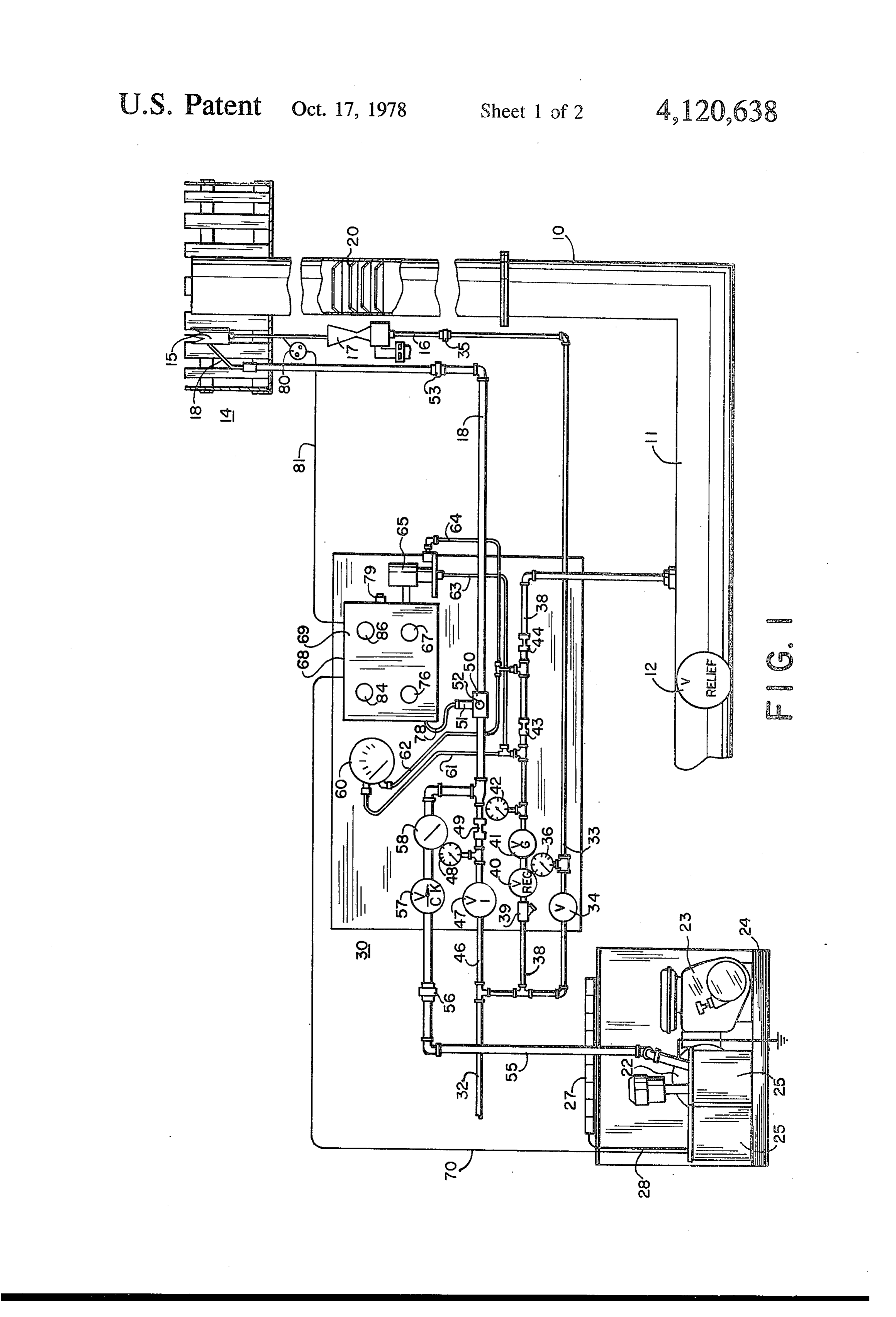
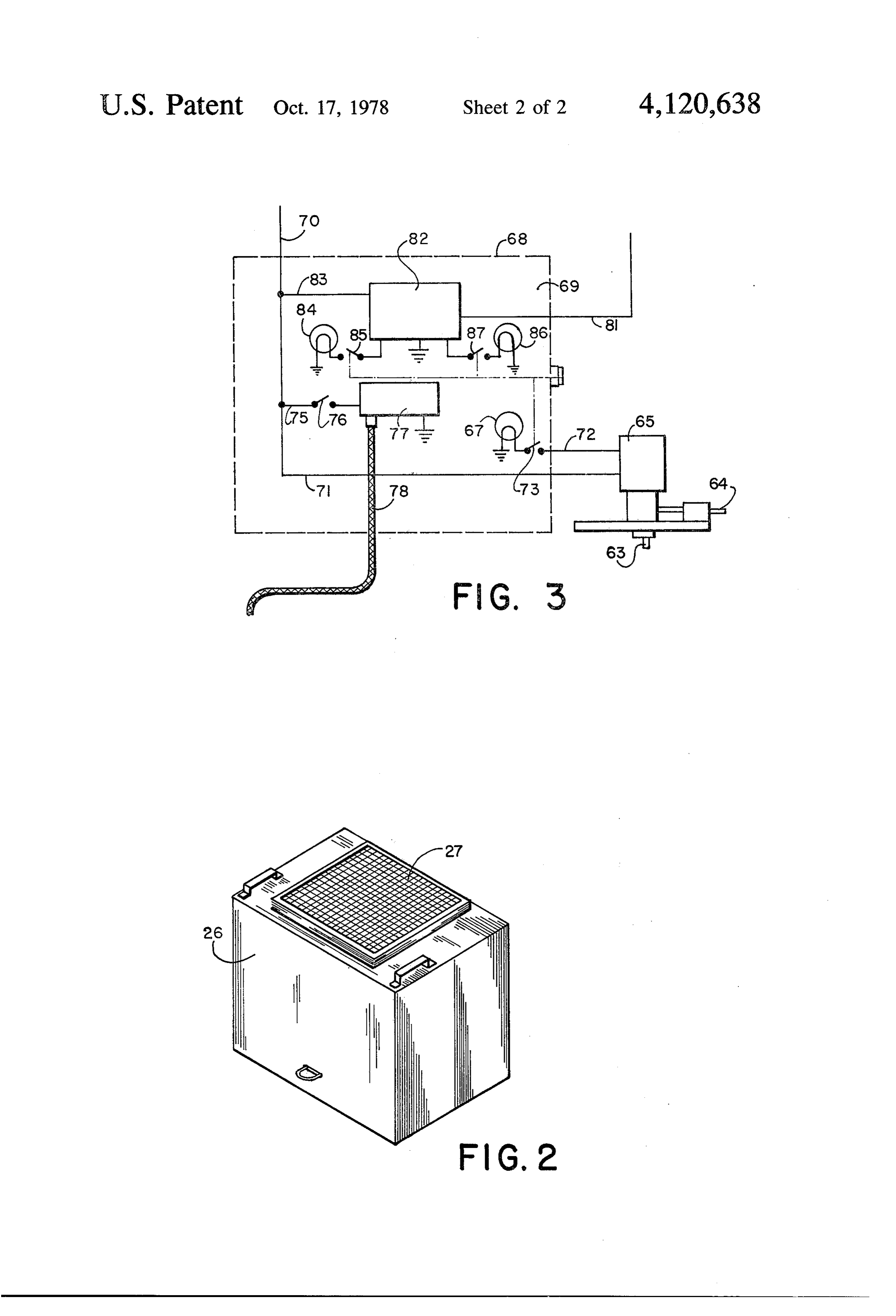
FIG. 3 is a diagrammatic view, enlarged, of a portion
Page 2drawing sheetscan →
Page 3drawing sheetscan →
Page 4scan →
FIG. 3 is a diagrammatic view, enlarged, of a portion
IGNITION SYSTEM FOR FLARES of the control system used in connection with the inven tion.
Background of the invention
It should, of course, be understood that the descrip 1. Field of the Invention tion and drawings herein are illustrative merely and that This invention relates to an ignition system for flares. various modifications and changes can be made in the which is particularly suitable for remote areas where structure disclosed without departing from the spirit of electricity and compressed air are not readily available the invention.
but where it is necessary to operate a flare for burning Like numerals refer to like parts throughout the sev of combustible waste gas. 10 eral views.
2. Description of the Prior Art DESCRIPTION OF THE PREFERRE Various ignition systems for flares have been pro EMBODIMENT posed for igniting combustible gas from industrial and other processes and including oil refineries. In perma Flares for the disposal by combustion of waste com nent installations such systems are provided to meet the 15 bustible gases can be vertical, horizontal or inclined. needs for continuous operation. For purposes of illustration of the invention, a flare In ignition systems it is also common to employ con stack 10 is shown, indicated as vertical, and with a flare trols for the delivery of pilot gas, to provide a flame to header 11 connected thereto for supplying waste com ignite the waste combustible gas and for the delivery of bustible gas to be burned. The flare header 11 prefera air and combustible gas to provide a flame for igniting 20 bly has a relief valve 12 therein to permit the waste the pilot. One such system is shown in my prior applica combustible gas to be delivered through the header 11 tion for Letters Patent, filed Feb. 6, 1976, Ser. No. and stack 10 for burning.
655,852. The flare stack 10 is shown also merely by way of No ignition system has heretofore been available for illustration as being provided at the discharge end with use with flares in remote areas where electricity and/or 25 a hollow cylindrical slotted wind shield 14 closed at the compressed air are not readily available although fuel bottom to reduce the wind effect at the end of the stack gas is available for operating pilot and ignitors and, if 10. Disposed within the wind shield 14 is a pilot 15 to desired, for purge gas. which a gas-air mixture is provided supplied by a pilot SUMMARY OF THE INVENTION gas pipe 16 and through a venturi 17 where air is ad 30 mixed for burning of gas at the pilot 15. The pilot 15
In accordance with the invention an ignition system also has an ignitor pipe 18 connected thereto for the for flares is provided which is particularly suitable for delivery of flame to the pilot for igniting the gas at the use in remote areas where electricity or compressed air pilot 15.
are not readily available but where adequate provisions The stack 10, close to the discharge end, is preferably must be made for igniting combustible waste gas in a 35 provided with a fluidic seal 20 as shown in my U.S. Pat, flare. The system includes a self-contained gasoline No. 3,730,673, for permitting free outward flow of gas engine driven blower and an electric power source with but for preventing inward flow within the stack 10. provisions for manual control of the delivery of air and A source of air under pressure is provided and for this fuel gas for ignition, for the delivery of purge gas for purpose a blower 22 driven by a gasoline engine 23 is purging the flare and for the delivery of pilot gas for employed, preferably mounted on a base 24, which base pilots at the discharge end of the flare. 24 may also have mounted thereon storage batteries 25 It is the principal object of the present invention to which serve as an electric power source. A removable provide an ignition system for flares which is simple in cover 26 is provided. The top wall of the cover 26 construction, and is readily operable by relatively un preferably has mounted thereon a plurality of intercon skilled persons. R 45 nected solar batteries 27 to provide input by conductor It is a further object of the present invention to pro 28 to the storage batteries 25. The solar batteries 27 can vide an ignition system for flares in which a solar bat be activated by exposure to the sun at the place of use of tery is provided for energizing storage batteries utilized the system.
as a source of electric energy for operation of the sys The unit comprising the blower 22, gasoline engine tem. 50 23, storage batteries 25 and the cover 26 with the solar It is a further object of the present invention to pro batteries 27 is one component of the system and is avail vide an ignition system for flares which can, if desired, able for movement to the place of use. be moved from place to place as required by separation A panel 30 is provided for the mounting of indicators, of readily separable components and without the neces control valves and other equipment, as hereinafter de sity for dismantling. 55 scribed and is also available for movement as a unit to Other objects and advantageous features of the inven the place of use.
tion will be apparent from the description and claims. A connection 32 to a source of combustible fuel gas is DESCRIPTION OF THE DRAWINGs provided which is connected by a pipe 33 through a manually operable pilot gas control valve 34 and a de
The nature and characteristic features of the inven tachable coupling 35 to the pilot gas pipe 16 carried on tion will be more readily understood from the following the stack 10. A pressure gage 36 is provided in the pipe description taken in connection with the accompanying 33 beyond the valve 34 for observation of the pressure drawings forming part hereof in which: prevailing in the supply pipes 33 and 16 to the pilot 15. FIG. 1 is a diagrammatic view of an ignition system A pipe 38 can also be provided connected to the pipe for flares in accordance with the invention; 65 32 for the supply of purge gas to the header 11 and has FIG. 2 is a perspective view of the separable cover interposed therein, and carried on the panel 30, a for the air and electric supply utilized with the system strainer 39, a pressure regulator 40, a manually con and having a solar battery mounted thereon; and trolled purge gas valve 41 and a pressure gage 42.
Page 5scan →
Spaced metering orifices 43 and 44 are also provided in perature responsive switch 82 to indicate whether or the pipe 38 for purposes to be explained. not the pilot 15 is operating with a visual signal from the A pipe 46, connected to the pipe 32, is provided and lamp 84 or the lamp 86. The simultaneous manual oper is connected through a manually operable ignition gas ation of the switches 73, 85 and 87 by the manual opera valve 47. The pipe 46 is carried on the panel 30, and is tor 79 will give the appropriate indication on the lamps provided with a pressure gage 48 and a metering orifice 84 or 86 as to pilot operation and at the lamp 67 as to 49 and extends to an ignition coupling 50. The coupling purge gas flow. The purge gas should not of course be 50 has an igniting spark plug 51 and a sight port 52. The flowing if waste combustible gas is being supplied to the igniter pipe 18 extends from the ignition coupling 50 to header 11 but should be flowing if there is no waste the pilot 15 through a detachable coupling 53. 10 combustible gas flow to the header 11. The purge gas The blower 22 is connected by a pipe 55 having a flow acts with the fluidic seal 20 to prevent backflow detachable coupling 56, a check valve 57 for preventing and internal explosions.
backflow and a butterfly valve 58 for controlling the air Indication of the flow will be available on the differ flow. The pipe 55 is connected to the gas pipe 46 be ential pressure gage 60. The purge gas flow is ordinarily yond the metering orifice 49 for mixing air with the fuel 15 supplied to prevent the presence of oxygen from the air gas to provide an explosive mixture. in the flare header 11 and the flare stack 10 when the - In order to measure the flow in the purge gas pipe 38 pilot is in operation.
a differential pressure gage 60, mounted on the panel 30, I claim:
is provided having a connection 61 to the pipe 38 up 1. An ignition system for flares comprising stream of the metering orifice 43 and a downstream 20 a flare stack, a pilot for igniting gas discharged from connection 62 upstream of the metering orifice 44 with said flare stack, connections 63 and 64 to a differential pressure switch an igniter pipe extending to said pilot for directly 65. The switch 65 controls a purge failure lamp 67 con initiating the operation of said pilot by flame propa tained within a control box 68 mounted on the panel 30, gation thereto, the lamp 67 being visible through the front cover 69. 25 a portable source of electric energy, A power input line 70 from the batteries 26 is pro a source of fuel gas for ignition and for pilot gas vided and has a connection 71 extending to the pressure supply, switch 65 and a connection 72 therefrom to the lamp 67 portable means for supplying air under pressure for through a switch 73. admixture with fuel gas from said source and for The line 70 is connected by a conductor 75 through a 30 delivery to said igniter pipe, manually operable push button switch 76 accessible on an ignition coupling to which said source of gas and the exterior of the control box 68 to a spark coil 77. A said means for supplying air are connected through sparkplug energizing line 78 extends from the spark coil manually controlled valves for said air and said gas 76 to the spark plug 51. and which is connected to said igniter pipe, A thermocouple 80 is provided contiguous to the 35 said ignition coupling having a spark plug connected pilot 15 which is connected by a conductor 81 to a thereto energized by a spark coil, temperature operated switch 82 having a plurality of a manually operable switch connected to said source positions. The temperature operated switch 82 has an of electric energy and to said spark coil for energiz input conductor 83 connected to the power line 70. A ing said spark plug for delivering a flame for propa lamp 84 is provided, visible at the front of the box 68, gation in said igniter pipe, and for indicating the "on' condition of the pilot 15 and is a fluid connection to said pilot from said source of controlled by a switch 85. A lamp 86 is provided visible fuel gas and having an air induction device therein. at the front of the box 68 for indicating the "off condi 2. An ignition system as defined in claim 1 in which tion of the pilot 15 and is controlled by a switch 87. The an indicating means is provided for indicating the contacts of the switches 73, 85 and 87 are mechanically 45 operating condition of said pilot, connected to a manual operator 79 for simultaneous a temperature responsive member is located contigu actuation of the switches 73, 85 and 87 to prevent con ous to said pilot, and tinuous energization of the lamps 67, 84 and 86 and said indicating means is responsive to said tempera reducing drain on the batteries 26. ture responsive member. The mode of operation will now be pointed out. 50 3. An ignition system as defined in claim 1 in which The gasoline engine 23 is started and operates the a purge gas connection is provided for said flare blower 22. stack, and
When it is desired to light the flame of the pilot 15 said purge gas connection is in communication with and with the valves 58 and 47 in adjusted positions to said source of fuel gas.
provide the proper mixture and with valve 34 open to 55 4. An ignition system as defined in claim 1 in which supply gas through the pipe 33 and the pipe 17 to the said means for supplying air is a blower contiguous to pilot 15, the pushbutton 76 is momentarily closed. Upon said source of electrical energy. closing of the pushbutton 76 the spark coil 77 is effec 5. An ignition system as defined in claim 4 in which tive through the conductor 78 for activating the spark said blower is gasoline motor driven. plug 51 to ignite the combustible mixture of the gas 60 6. An ignition system as defined in claim 2 in which supplied through the pipe 46 and the air supplied said indicating means has manually controlled operat through the pipe 55 at the ignition coupling 50. The ing switches.
flame transmitted through the pipe 18 is effective for 7. An ignition system as defined in claim 1 in which igniting the flame at the pilot 15. The flame through the pressure indicating means is provided for said gas to pipe 18 can travel long distances which may be as great 65 said ignition coupling.
as one to two, thousand feet. At the same time, pilot 8. An ignition system as defined in claim 1 in which failure, if this should occur, will be indicated by the a purge gas connection is provided for said flare thermocouple 80 through the conductor 81 to the tem stack, and 6 means is provided for measuring the pressure in said 11. An ignition system as defined in claim 1 in which purge gas connection. said source of electrical energy and said means for 9. An ignition system as defined in claim 1 in which supplying air under pressure comprise a combined a purge gas connection is provided for said flare portable component, and stack, and a panel is provided for supporting said ignition cou indicating means is provided for indicating the flow pling, said valves and said manually operable in said purge gas connection. switch.
10. An ignition system as defined in claim 1 in which 12. An ignition system as defined in claim 1 in which a purge gas connection is provided for said flare said source of electrical energy comprises a storage stack, and 10 battery, and pressure responsive indicating means is provided a solar battery is provided for supplying electrical responsive to the pressure in said purge gas connec energy to said storage battery. tion. k l k
Provenance
- Collection
- Patents citing this work
- Pages
- 6
- Method
- pdftotext (the PDF's own text layer) + pdftoppm 300dpi page scans
- Patent office record
- patents.google.com →
- Source
- Google Patents citing-documents table
- Assignee
- Combustion Unlimited Incorporated
- Published
- 1978-10-17
- Transcribed from
- patentimages.storage.googleapis.com →