

patent · US4129117A
Solar energy collector
12 December 1978
Text
Page 1bibliographic recordscan →
United States Patent (19)
Harvey
(54). SOLAR ENERGY COLLECTOR
Inventor: Lawrence Harvey, Coldharbour Nr.
Dorking, England Assignee: The British Petroleum Company
Limited, London, England
(30) Foreign Application Priority Data
Int. Cl’................................................. F24J 3/02 52 U.S. C. ..................................... 126/271; 126/270
2,680,437 6/1954 Miller ................................... 126/270 3,064,418 11/1962 Sanders ................................ 126/270
3,102,532 9/1963 Shoemaker .......................... 126/271
3,951,129 4/1976 Brantley, Jr. ... 126/271 3,981,294 9/1976 Deminet et al. 126/271 4,030,477 6/1977 Smith ...................... ... 126/271
FOREIGN PATENT DOCUMENTS
472427 1/1952 Italy ......................................... 126/271 Primary Examiner-Kenneth W. Sprague
Assistant Examiner-James C. Yeung
Attorney, Agent, or Firm-Brooks, Haidt, Haffner & Delahunty
A solar energy collector comprising a transparent con tainer containing a particulate or fibrous radiation ab sorbing material and having a transparent outer cover through which a heat conveying fluid can pass before passing through the container.
17 Claims, 8 Drawing Figures
Drawings
Page 2drawing sheetscan →
Page 3drawing sheetscan →
Page 4drawing sheetscan →
Page 5drawing sheetscan →
Page 6scan →
The second transparent wall may be made from any
SOLAR ENERGY COLLECTOR of the materials suggested above for the transparent heat collecting zone wall, but preferably from the same
The present invention relates to solar radiation col material. It is positioned in the collector adjacent to the lectors. transparent heat collecting zone wall so as to define a Solar collectors for thermal conversion fall into two flow path zone for the heat conveying fluid leading to main categories: the collecting zone, through which the radiation passes 1. Collectors for high temperature conversion, the before it enters the collecting zone. Preferably the sec sun's rays being concentrated by concave reflectors ond wall extends over substantially the whole of that which track the sun during the day. This type of collec O part of the collecting zone which is designed to receive tor cannot be used effectively in diffuse light. solar radiation. Thus it forms a flow path Zone for the 2. The fixed "flat-plate” collectors which will con heat conveying fluid over this area. The second wall is vert direct or diffuse sunlight into heat, for tempera normally parallel to the transparent wall of the heat tures below 200 C. collecting zone in the direction of flow, thus forming a Typically a "flat-plate' collector of a type which has 15 flow path zone of uniform width in which the heat been used successfully in countries such as Israel and conveying fluid will move with uniform velocity. Al Japan comprises a circular metal tube bonded to a metal ternatively, the distance between the two walls can be plate which is mounted on an insulated surface. Heat varied in the direction of flow, with a corresponding absorbed by the plate passes into the heat collecting variation in the volume of the flow path zone and the fluid that is arranged to pass through the metal tubing. 20
To improve efficiency the collector is normally placed velocity dimensions of the heat conveying fluid. Preferably the of the flow path zone are uniform in the in a sealed box having a transparent cover which suit directions transverse ably is made with double glazing. Such units can have the volume is arrangedtotothebedirection of flow. Suitably approximately the same as an efficiency of about 40% at 50 C.
For this type of collector to be of use in higher lati larger or smaller depending on the flow rates it istimes 25 that of the collecting zone, but it may be many tudes, where the angle of incidence of the solar radia sired to use. For most types of collector the two walls tion is lower, particularly during winter months, the are suitably separated by about 1/16 to inch. conversion efficiency has to be much improved.
My copending U.S. application Ser. No. 622,982, of Inthea transparent particularly preferred embodiment one or both flow path zone and the heat collect filed Oct. 16, 1975, now abandoned, discloses a solar 30 ing zone comprise an integrally formed strip of parallel collector comprising a transparent heat collecting Zone transparent tubes. Each strip of tubes is preferably and energy absorbent particles or fibres having a den formed as a layer of tubes lying adjacent to one another sity not greater than 1.1 present in said Zone.
An object of the present invention is to provide an wherein
The the longitudinal axes of the tubes are coplanar.
tubes preferably have a square or rectangular
Accordingly the present invention provides a solar cross-section, two opposite sides of each tube forming energy collector comprising a heat collecting Zone con top and bottom surfaces of the strip and each of the taining energy absorbent particulate or fibrous material other opposite sides forming a common side with an and having a first transparent wall through which solar adjacent tube except at the longitudinal edge of the strip energy can pass, a second transparent wall mounted where the edge tubes have only one side common with adjacent to the first wall so as to form a transparent flow an adjacent tube. In one preferred embodiment the path zone through which the radiation passes before transparent flow path Zone and the heat collecting zone entering the collecting zone, and inlets to and outlets are formed integrally as a double layer of parallel trans from the collecting zone and the flow path zone for heat parent tubes in which the top surface of each tube in the conveying fluid, the outlet from the flow path zone 45 lower layer forms a common side with an adjacent tube being connected to the inlet of the collecting zone. in the upper layer. The upper layer of tubes collectively The heat collecting zone is suitably comprised by a form the flow path zone, while the lower layer of tubes hollow container equipped with one or more inlets and collectively form the collecting zone. The outlet from outlets to enable the heat conveying fluid to flow the flow path zone can be connected to the inlet of the through the container. The container can have any 50 collecting zone by a manifold section. Likewise the inlet desired shape but preferably has a flat box shape. The to the transparent flow path zone and the outlet from container may be formed entirely from a transparent the heat collecting zone both suitably consist of an inlet material, for example lay-flat plastic tubing, but it is pipe and a manifold. The tubes are preferably formed by preferred to make transparent only the wall adapted to extrusion or blow-moulding. In another embodiment receive the incident sunlight, the other walls preferably 55 the flow path zone is formed from a single layer of being made black on the inner surface and reflective on integrally formed parallel transparent tubes in the lower the outer surface and/or being heat insulated on the part of each of which is positioned an internal tube outside. The transparent material employed is prefera containing the energy absorbent particulate or fibrous bly transparent to as large a proportion of the solar material, the internal tubes collectively forming the heat spectrum, including infra-red, visible and ultra-violet collecting zone. The internal tubes are connected to radiation as possible and should not soften at tempera gether at either end by suitable manifold pieces. tures likely to be encountered in the operation of the The heat collecting zone may be made from a differ collector. Suitable transparent materials include glass, ent material to the transparent wall forming the flow polymethyl methacrylate, cellulose, acetate, polyethyl path zone. For instance the latter wall may be con ene, polystyrene, polycarbonate, clear P.V.C. and mica. 65 structed of polycarbonate, and the heat collecting zone Plastics material such as P.V.C. and polycarbonate are formed of other material having superior stress proper especially suitable, as they have low thermal conductiv ties in contact with hot water, for instance PVC, polyvi ity. The use of polycarbonate is preferred. nylidene chloride, clear high density polyethylene, 7 clear acrylonitrile/butadiene/styrene resin, methyl me pump. Alternatively, water may be gravity fed to the thacrylate/butadiene/styrene resin, or Barex resin. collector and thence piped to, e.g. a storage tank. The energy absorbent particulate or fibrous material If the heat conveying fluid is a low boiling liquid, it contained in the heat collecting zone of the present can be allowed to vapourise in the heat collecting zone invention is suitably made from any material capable of 5 and heat will be absorbed as latent heat of vapourisa effectively absorbing solar radiation. The density of the tion. The vapour can be allowed to pass to a heat ex particles of fibres is preferably not greater than 1.1, and changer acting as a condenser for the vapour and be most preferably in the range 0.9 to 1.0. Preferred mate made to give up its latent heat. For example, this heat rials from which the particles or fibres are made are can be used to pre-heat cold water flowing into hot carbon, for example carbon or graphite pellets or car 10 water tanks. The condensed vapour is then returned to bon fibres; carbon filled plastics or rubber, for example the solar collector.
carbon filled polyethylene pellets or fibre or granulated If desired, several solar radiation collectors can be scrap motor car tyres; blackened expanded perlite parti linked together in series and/or in parallel. The collec cles; bitumen or modified bitumen chippings; chemi tors can also be manufactured to form interlocking cally blackened metal wool or metal particles; and black 15 sheets which can be used to cover a roof. Such systems glass particles or dark flint chippings. Materials having can provide hot water, for example for domestic use or high solar energy absorption and low thermal diffusiv heating a swimming pool, for process hot water in in ity (e.g. preferably below 2.5 x 10-cms/sec attem dustry, or for heating air for space heating or drying peratures above 20° C), for example carbon filled high applications.
density polyethylene, are particularly preferred. 20 As is conventional with solar radiation collectors, Where the energy absorbent material is particulate those of the present invention can be fitted with "double the particles can be for example discrete granules, pel glazing", i.e. a further transparent sheet is mounted lets, beads tubelets or chippings, or a porous sintered above the second transparent wall and the whole unit is mass of the particles. Cylindrical hollow pellets or tube sealed to prevent free access of air to the outer surface lets are preferred. The particles preferably have a mean 25 of the second transparent wall. This can reduce heat particle diameter in the range 1 to 10 millimeters, more loss to the atmosphere through the wall but it will be preferably 3.0 to 4.0 mm. The particles preferably sub appreciated that with collectors according to the pres stantially fill the heat collecting zone but are loosely ent invention the need to prevent this loss of heat en packed so that when a liquid is passed through they are ergy is reduced because of the heat conserving effect of not entirely static but are free to move to a limited 30 the relatively cool heat conveying fluid passing through extent within the confines of the heat collecting zone. the flow path zone.
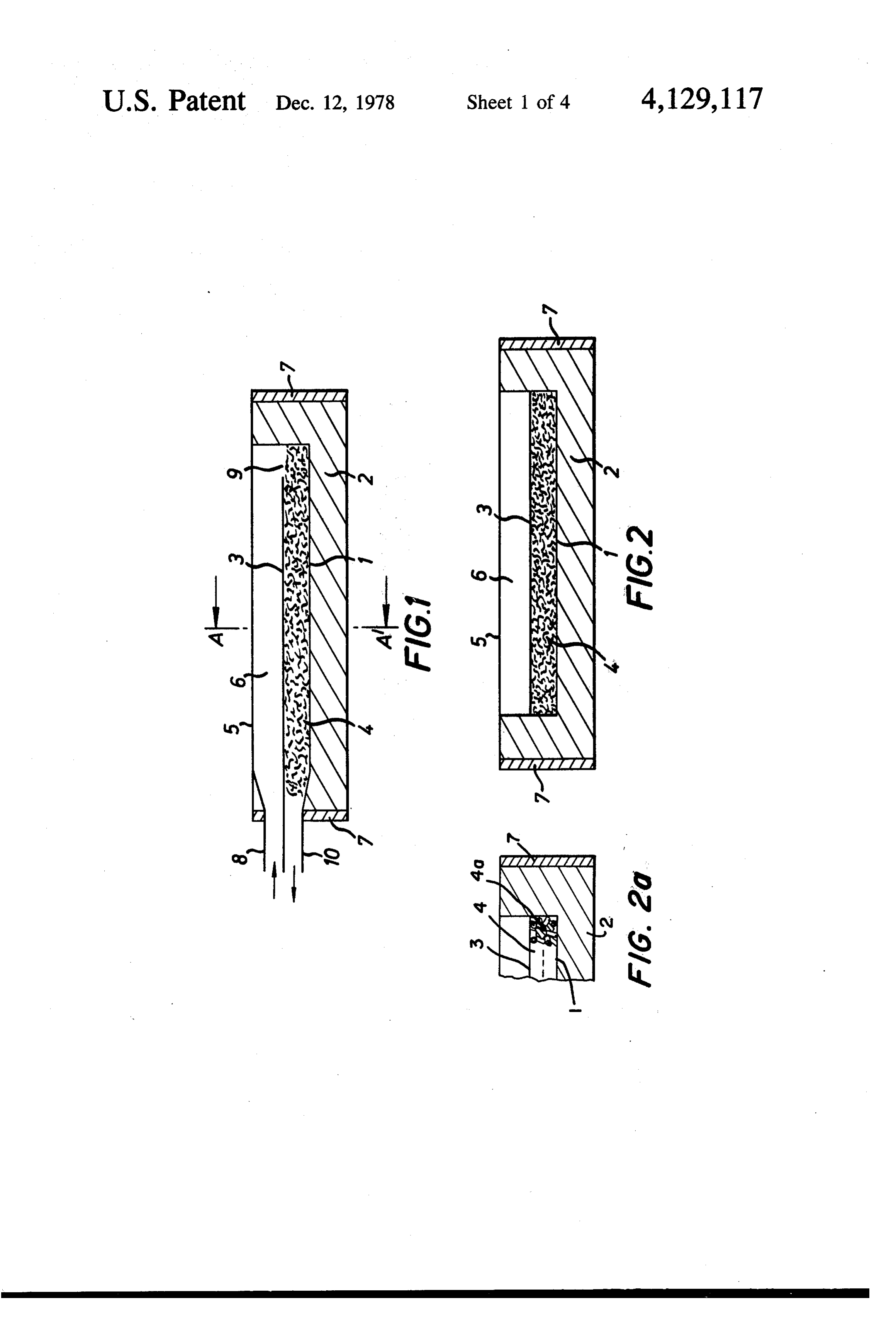
The energy absorbent particulate or fibrous material is The accompanying diagrammatic drawings FIGS. 1 confined to the heat collecting zone by an outlet to 5 illustrate two solar radiation collectors according through which the heat conveying fluid, but not the to the present invention.
particulate or fibrous material, can pass. 35 FIG. 1 represents a vertical cross-section through The heat conveying fluid must be wholly or partially one collector, and transparent to solar energy and can be a liquid or a gas, FIG. 2 represents a vertical cross-section through the examples of suitable fluids being water, water/anti same collector in a direction at right angles through the freeze mixtures, alcohols such as glycerine, oil air, car line A-A in FIG. 1.
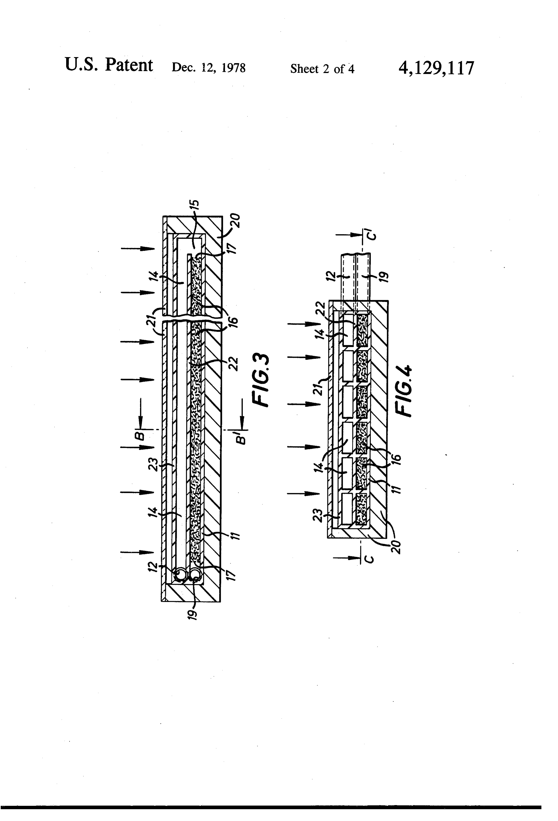
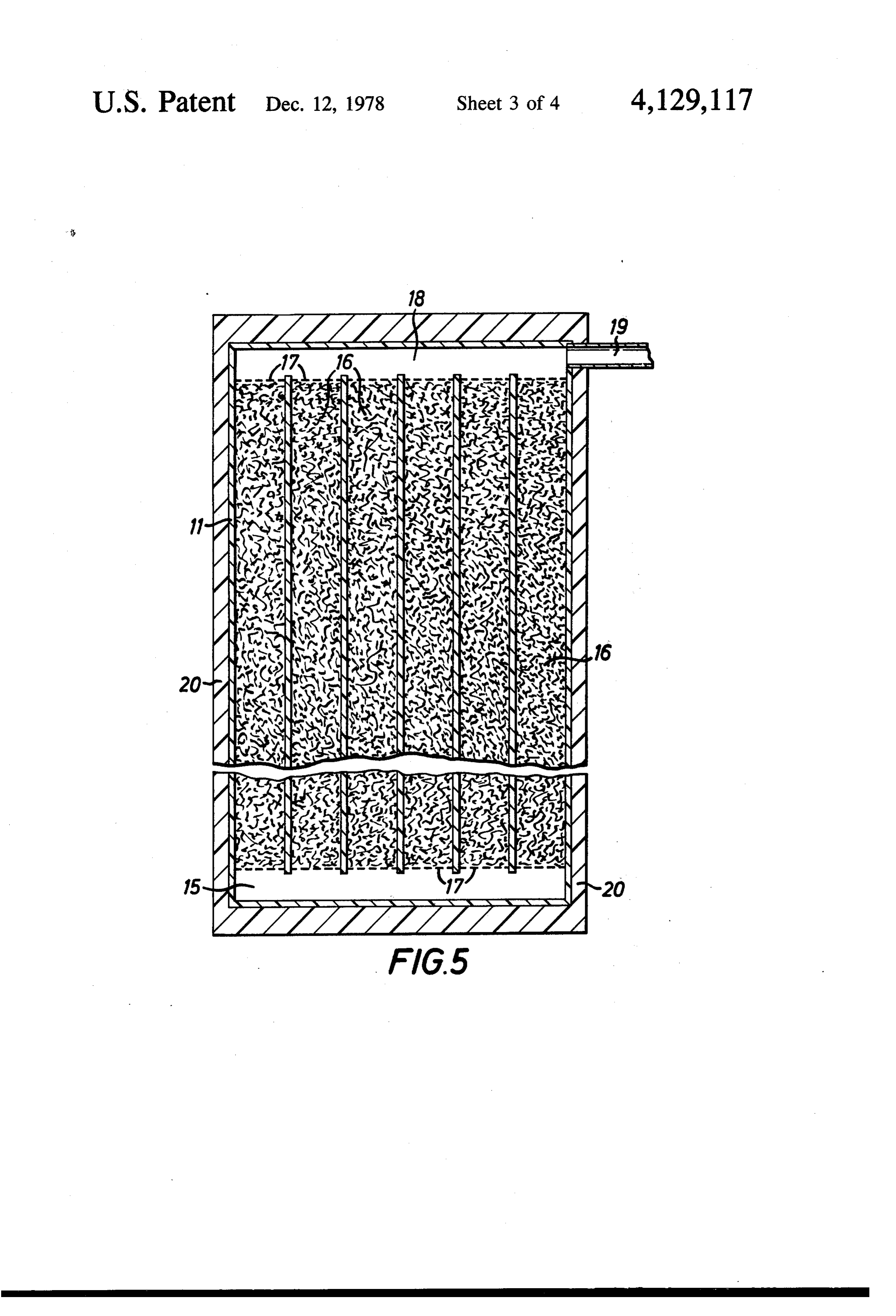
bon dioxide, or high aliphatic hydrocarbons. Good FIG. 2a is similar to FIG. 2 but shows cylindrical results are obtained using water as the heat conveying hollow pellets as the energy absorbent material. fluid. The heat conveying fluid should be chosen to be FIG.3 represents a vertical cross-section through a compatible with the material of construction of the second collector according to the present invention, solar energy collector. Thus methanol would not be and suitable for use in a collector constructed from polycar 45 FIG. 4 represents a vertical cross-section through the bonate. same collector in a direction at right angles through the There is a reduction in energy losses in collectors line B-B in FIG. 3.
according to the present invention, due to reduced re FIG. 5 represents a horizontal cross-section through radiation and conduction of energy from the collector, the line C-C in FIG. 4.
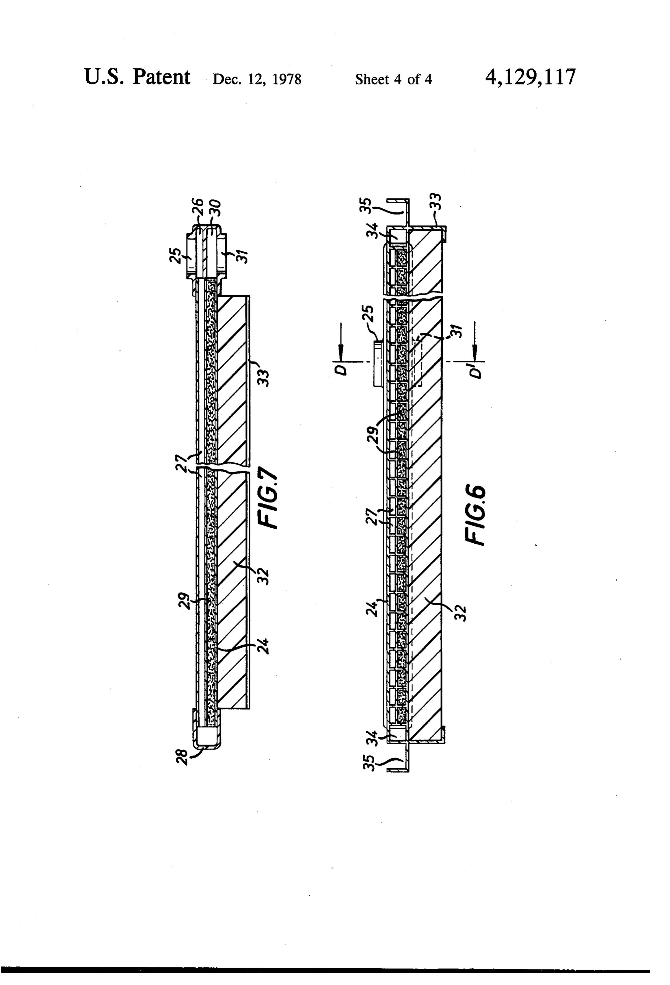
energy losses from the collecting zone by radiation and 50 FIG. 6 represents a vertical cross-section through a conduction being recovered by absorption in the flow third collector according to the present invention, and path zone. Because the incoming heat conveying fluid FIG. 7 represents a vertical cross-section through the in the flow path zone is comparatively cold, radiation same collector in a direction at right angles through the and conduction from the collector to the environment is line D-D in FIG. 6.
reduced. 55 Referring to FIGS. 1 and 2 the collector is formed by In operation a heat conveying fluid is passed through a flay tray1 mounted on an insulated base 2 and covered the energy collector. The fluid first enters the flow path by a transparent wall 3 to form a heat collecting zone 4 zone defined by the two transparent walls and passes which is filled with a fibrous mat made from polyethyl from the flow path zone into the heat collecting zone. It enefilled with 2% of carbon black. Above the transpar is heated by the solar energy in the collecting zone and ent wall 3 a second transparent wall 5 is mounted to then passes from the collector through the outlet there form a flow path zone 6. The tray and walls are sealed from. The inlet and outlet pipes may be connected to, together to make a fluid tight system and the whole unit for example, a heat exchanger in a hot water storage is mounted in a frame 7. In operation fresh and rela tank, or if water is used as the heat conveying fluid they tively cool heat conveying fluid passes into the unit may be connected directly to the tank. The fluid may be 65 through inlet 8 and moves across the flow path zone 6 circulated, for example either by arranging the system and passes into the collecting zone through inlet 9. It so that the fluid heated by the solar radiation thermally then passes through the collecting zone removing heat syphons into the tank or by employing a low power energy that has been absorbed on the black fibrous mat 8 material. Finally it leaves the unit through outlet 10 and first fluid passageway for the passage of fluid therebe passes to a heat storage unit or heat exchange unit. . tween and in contact with said walls, said passageway FIG.2a shows cylindrical hollow pellets 4a which having an inlet and an outlet spaced from said inlet and may be used in place of the fibrous mat shown in FIGS. being free of solar energy obstructing material so that in 1 and 2. . . the absence of said fluid, solar energy passing through Referring to FIGS. 3-5, the solar collector comprises one of said walls is permitted to traverse said passage an integrally formed strip, 11, extruded from a transpar way and pass through the other of said walls; means ent thermoplastic and comprising twelve parallel tubes including a third wall in spaced, and side-by-side rela arranged in two layers of six tubes, each having a rect tion with said other of said walls and defining, between angular cross-section. At one end of the strip 11 is an 10 said third wall and said other wall, a second fluid pas inlet pipe 12 connected by an inlet manifold 13 to the sageway for the passage of said fluid which is disposed upper layer of six tubes, which collectively form the in the path of solar energy which passes through said flow zone 14 defined by a first transparent wall 22 com pair of walls, said second passageway having an inlet mon to both zones and a second transparent wall 23. At connected to said outlet of first passageway and having the other end of the strip a connecting manifold 15 15 an outlet spaced from said last-mentioned inlet, connects the flow path zone to the lower layer of six whereby fluid supplied to said inlet of said first passage tubes, which collectively form the heat collecting zone way flows therealong to said outlet of said first passage 16. The heat collecting zone 16 is loosely packed with way and in the path of the solar energy and then flows carbon blackfilled high density polyethylene fibres held from said inlet of said second passageway to the outlet in place by perforated strips 17. At the same end of this 20 of the latter; solar energy absorbent particulate or fi strip as the inlet pipe 12, an outlet manifold 18 connects brous material disposed in said second passageway for the tubes of the heat collecting zone to the outlet pipe absorbing solar energy which passes through said pair 19. The solar collector is backed by foamed thermoplas of walls, said material being permeable by and in the tic 20 to minimise heat losses from the under surface. A path of fluid flow in said second passageway, whereby transparent sheet of thermoplastic 21 provides insula 25 said fluid contacts said material and absorbs heat there tion to the side adapted to receive solar radiation. In from; and means for restraining said material from flow operation fresh and relatively cool heat conveying fluid ing out of said second passageway. passes into the solar collector through inlet pipe 12 and 2. A solar energy collector as set forth in claim 1 manifold 13, through the flow path zone 14, and into the wherein said pair of walls and said third wall are flat heat collecting zone 16 via connecting manifold 15. In 30 and in substantially parallel relation. the heat collecting zone the heat conveying fluid re 3. A solar energy collector as set forth in claim 1 moves heat energy that has been absorbed in the black wherein said third wall is black on its surface facing said mat of polyethylene fibres. The heat conveying fluid second passageway and the surface facing away from leaves the solar collector via outlet manifold 18 and said passageway has heat conserving means. outlet pipe 19. 35 4. A solar energy collector as set forth in claim 3 The integrally formed strip 11 may also be made by wherein said heat conserving means is a solar energy blow-moulding for instance from polycarbonate resin reflector.
and may comprise any number of parallel tubes in two 5. A solar energy collector as set forth in claim 3 layers. wherein said heat conserving means comprises heat Referring to FIGS. 6 and 7, the solar collector com insulating material.
prises an integrally formed strip 24 extruded from poly 6. A solar energy collector as set forth in claim 1 carbonate resin and having a number of parallel tubes wherein said one wall is co-extensive with said heat arranged in two layers each having a rectangular cross absorbent material.
section. At one end of the strip 24 in a central position 7. A solar energy collector as set forth in claim 1 is an inlet pipe 25 connected by an inlet manifold 26 to 45 wherein said first-mentioned means and said second the upper layer of tubes, which collectively form the mentioned means are an integral pair of tubes having a flow path zone 27. At the other end of the strip 24 a common wall which is said one of said pair of walls. connecting manifold 28 connects the upper layer of 8. A solar energy collector as set forth in claim 1 tubes with the lower layer of tubes which collectively further comprising partition means in at least one of said form the heat collecting zone 29. The heat collecting 50 passageways and extending between the inlet and outlet zone 29 is loosely packed with carbon black filled high thereof, said partition means sub-dividing said one pas density polyethylene fibres. At the same end of the strip sageway into a plurality of sub-passageways. 24 as the inlet pipe 25, an outlet manifold 30 connects 9. A solar energy collector as set forth in claim 1 the tubes of the heat collecting zone to the outlet pipe wherein one of said pair of walls and at least one of the 31. A layer of foamed thermoplastic 32 held in place by 55 other of said pair of walls and said third wall are formed the skirt 33 provides insulation for the under surface of by a plurality of parallel tubes each integral with the the solar collector. On either side of the strip 24 the tube adjacent thereto.
outer most rectangular tube 34 provides insulation at 10. A solar energy collector as set forth in claim 9 the edges and does not form part of the heat collecting wherein each tube has a rectangular cross-section. zone 29. At each edge an integrally formed gutter 35 is 11. A solar energy collector as set forth in claim 1 provided to allow drainage of rain water. Panels of the wherein said material has a density not greater than 1.1. type shown in FIGS. 6 and 7 can be laid side by side and 12. A solar energy collector as set forth in claim 11 linked together at the gutter edges by U-shaped pieces wherein the density of said material is in the range from so as to cover part or all of a roof surface. 0.9 to 1.0.
I claim: 65 13. A solar energy collector comprising means in 1. A solar energy collector comprising means includ cluding a first solar energy transparent wall; a third wall ing a pair of solar energy transparent walls in spaced, spaced from said first wall; a second energy transparent side-by-side relation and defining between said walls a wall intermediate and spaced from said first wall and 9 made of the same material and are integral with each said third wall, each wall being substantially parallel to each adjacent wall; partition means extending between other.
said first wall and said second wall and between said 16. A solar energy collector as set forth in claim 15 second wall and said third wall and forming a plurality wherein said material of each said wall and said parti of first fluid passageways between said first wall and 5 tion means is a polycarbonate resin. 17. A solar energy collector comprising means in said second wall and a plurality of second fluid passage cluding a pair of solar energy transparent walls in ways between said second wall and said third wall, each spaced, side-by-side relation and defining between said first passageway having a wall in common with a sec walls a first fluid passageway ond passageway; inlet means for supplying fluid to one for the passage of fluid end of each first passageway; outlet means intercon 10 therebetween and in contact with said walls, said pas sageway having an inlet and an outlet spaced from said necting the opposite end of each of said first passage ways to the adjacent end of each of said second passage inlet; means including a third wall in spaced, and side ways; means for removing fluid from the end of each of betweenrelation by-side with one of said walls and defining, said second passageways which is opposite from the end 15 passageway for thewall said third and said one wall, a second fluid passage of said fluid which is dis thereof connected to said first passageways, whereby posed in the path of solar energy which passes through fluid supplied to said one end of each of said first pas said pair of walls, said second passageway having an sageways flows therealong in contact with said first wall and said second wall to said opposite end thereof inlet connected to said outlet of said first passageway and having an outlet spaced from said last-mentioned and then flows from said adjacent end of each of said 20 inlet, whereby fluid supplied to said inlet of said first second passageways to said opposite end thereof; solar passageway flows therealong to said outlet of said first energy absorbent particulate or fibrous material dis passageway and in the path of the solar energy and then posed in said second passageways for absorbing solar flows from said inlet of said second passageway to the energy which passes through said first wall and said outlet of the letter; cylindrical hollow pellets or tubulets second wall, said material being permeable by and in the 25 of solar energy absorbent material disposed in said sec path of the fluid flow in said second passageways, ond passageway for absorbing solar energy which whereby said fluid contacts said material and absorbs passes through said pair of walls, said pellets or tubulets heat therefrom; and means for restraining said material being permeable by and in the path of the fluid flow in from flowing out of said second passageways. said second passageway, whereby said fluid contacts 14. A solar energy collector as set forth in claim 13 30 said pellets or tubulets and absorbs heat therefron; and wherein said outlet means comprises a manifold. means for restraining said pellets or tubulets from flow 15. A solar energy collector as set forth-in claim 13 ing out of said secondIt passageway.
wherein each said wall and said partition means are
Provenance
- Collection
- Patents citing this work
- Pages
- 9
- Method
- pdftotext (the PDF's own text layer) + pdftoppm 300dpi page scans
- Patent office record
- patents.google.com →
- Source
- Google Patents citing-documents table
- Assignee
- The British Petroleum Company Limited
- Published
- 1978-12-12
- Transcribed from
- patentimages.storage.googleapis.com →