

patent · US4130786A
Apparatus for generating linear and continuous positional error and velocity signals for higher order servo systems
19 December 1978
Text
Page 1scan →
United States Patent (19)
Jacques
54 apparatus for generating linear
And continuous positonal error
And velocity signals for higher
Order servo systems
75 Inventor: James O. Jacques, Tracy, Calif.
73 Assignee: Xerox Corporation, Stamford, Conn.
51) Int. C.’.............................................. G05B 13/00 52 U.S. C. .................................... 318/561; 318/608;
3,475,626 10/1969 Holzman et al. .................... 307/262 3,699,555 10/1972 DuVall.............. ... 318/617 4,059,086 9/1977 Cosksedge ... 318/608 4,059,789 11/1977 Cocksedge ... ... 318/608 Primary Examiner-B. Dobeck
Converter
Attorney, Agent, or Firm-Barry Paul Smith
A higher order servo system including a phase trans ducer which produces two triangular waveforms, phase displaced 90' in relation to each other, representing the positions of a movable member, and a commutating circuit, responsive to the triangular waveforms, for generating a sawtooth waveform and a velocity signal which is linear and continuous over the whole range of movement of the member. A counter and converter, responsive to pulses also generated by the commutating circuit, generates a. staircase waveform, representing predetermined positions of the member, which is added to the sawtooth waveform to produce a positional error signal which is linear and continuous over the whole range of movement of the member. Optimal velocity and acceleration signals are derived from these two linear and continuous signals to drive the member to a desired position over the shortest path, in the minimal amount of time, and with no oscillatory motion at the desired position.
24 Claims, 15 Drawing Figures
Drawings
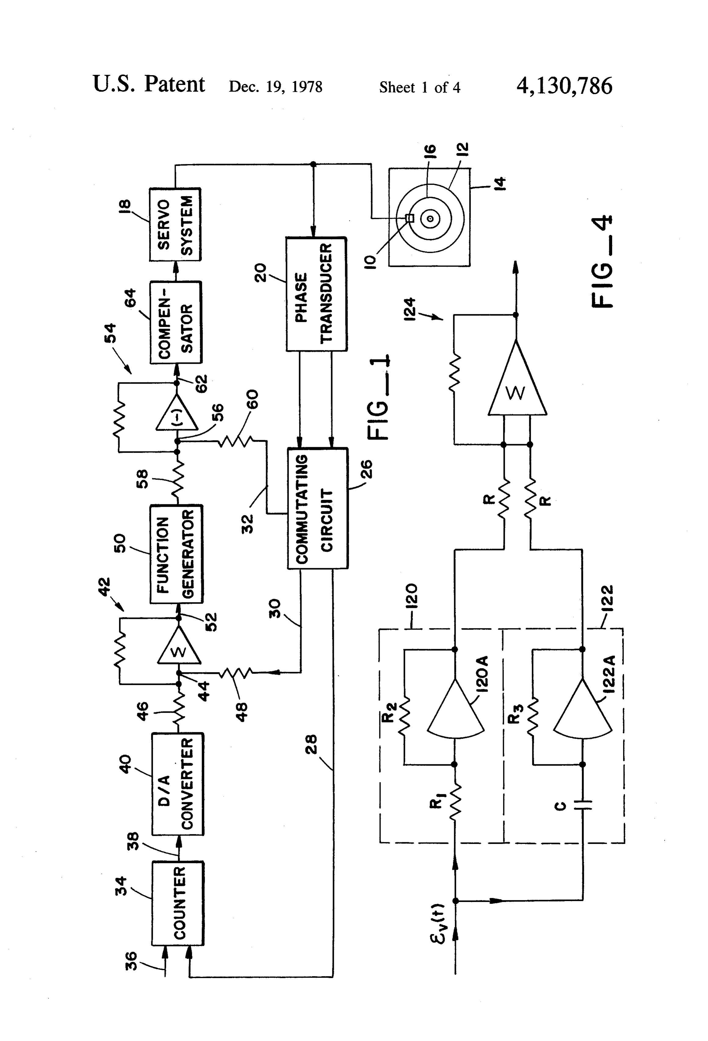
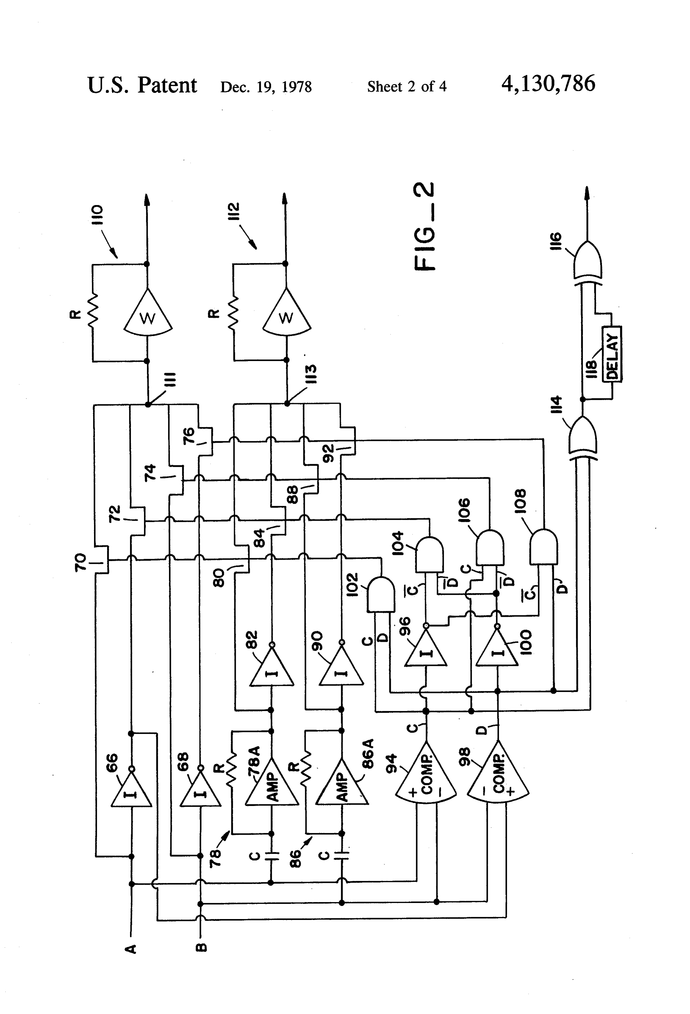
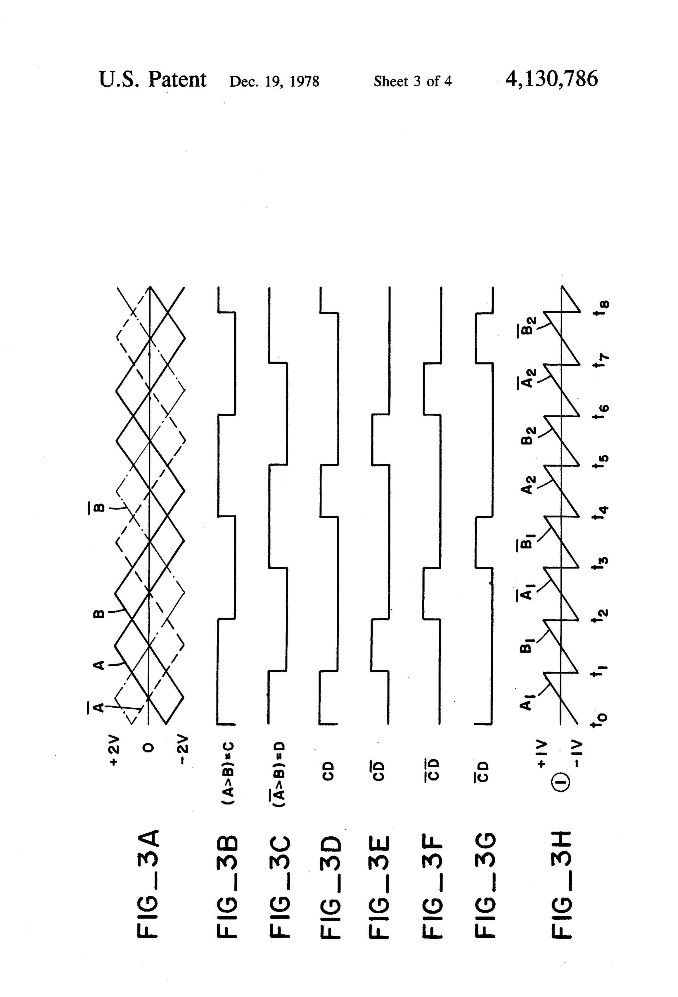
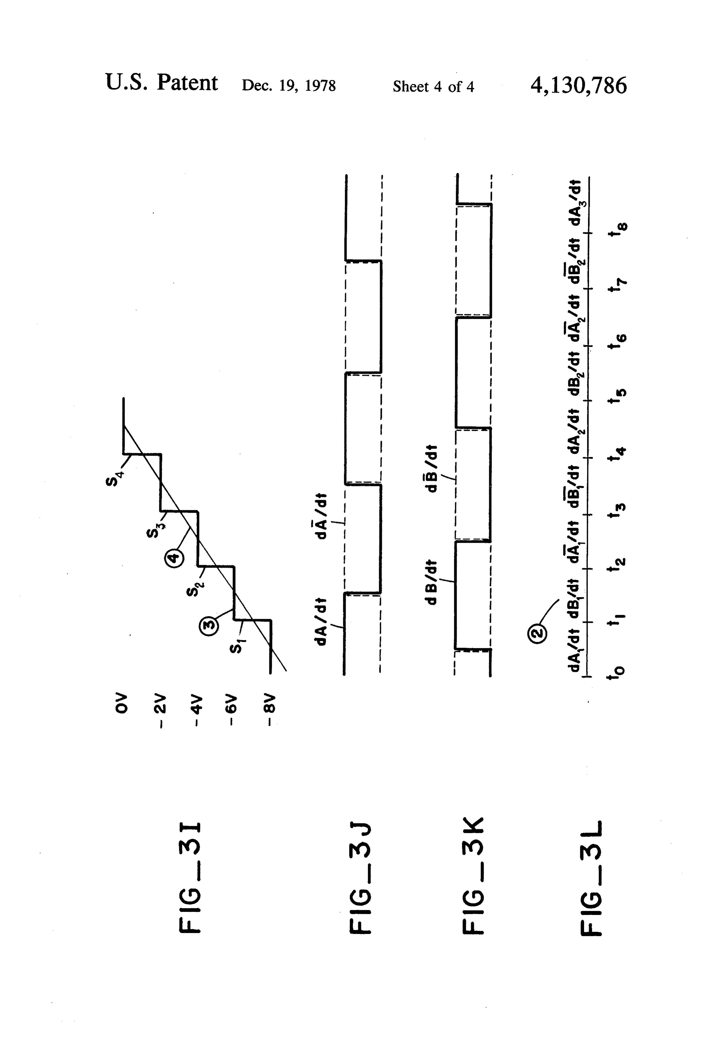
FIG. 4 illustrates the compensator 64. Compensator (b) a plurality of AND gates, each having an output 64 receives the velocity error signal e(t) which is fed to connected to a respective one of said switches, to an operator 120 having a transfer function k and an close said switches;
Page 2drawing sheetscan →
Page 3drawing sheetscan →
Page 4drawing sheetscan →
Page 5drawing sheetscan →
Page 6scan →
mentioned above in connection with second order sys
APPARATUS FOR GENERATING LINEAR AND tems.
CONTINUOUS POSITONAL ERROR AND In order for such second order or third order systems VELOCITY SIGNALS FOR HIGHER ORDER to operate optimally, in fact for any system of a higher SERVO SYSTEMS or lower order, it is desirable that the signals which BACKGROUND OF THE INVENTION drive the driving arrangements of each system be de rived from positional error and velocity signals which
The present invention relates to a positional control are free from nonlinearities and discontinuities. It is also system and to apparatus for providing control signals desirable to generate such positional error and velocity giving the positional control system an improved re O signals which are free of nonlinearities and discontinuit sponse characteristic. ies from a single transducer; however, until now this has Conventional positional control systems are com been a problem.
prised of a servo arrangement for driving a load to selected positions, control circuitry for operating the SUMMARY OF THE INVENTION driving arrangement to move the load, and signalling 15 It is an object of the present invention to provide a circuitry for generating error signals to which the con novel apparatus for obtaining linear and continuous trol circuitry is responsive to actuate the driving ar signals.
rangement. A theoretically perfect positional control It is another object of the present invention to pro system would (1) drive the load along the shortest path vide a novel positional control system having improved to a selected position, (2) drive the load to the selected 20 position in the shortest possible time, and (3) stop the response
A still characteristics.
further object of the present invention is to load at the selected position with no oscillatory motion. derive continuous and linear positional error signals and Stated another way, the ideal response to such control velocity signals from a single transducer in a positional systems is one in which the positional error is reduced control system.
exactly to zero with no overshoot and in the minimum 25 These and other objects of the present invention are time compatible with the capabilities of the available obtained by making use of a single transducer generat components of the system.
Conventional second order positional control sys ing twodisplaced signals of the same triangular waveform but tems have been implemented in an attempt to realize a phase with respect to each other and repre senting the positions of a load as it is moved to a se theoretically perfect control system. In such second 30 order systems, positional error signals are generated lected position. A commutating circuit means is respon using a position transducer and are indicative of a differ sive to these two signals to generate a sawtooth wave ence between the position of the load and the selected form, and a signal, representing the velocity of the load, position. A function generator is responsive to these which is linear and continuous over the full range of error signals and generates signals representing the 35 movement of the load. Another, staircase waveform is optimal velocity that the load should have at various generated in response to the phase displaced signals and positions as it moves towards the selected position. A provides information as to when the load arrives at rate signal generator or transducer is also employed to predetermined positions on its travel towards the se generate signals corresponding to the velocity of the lected position. This staircase waveform is added to the load at the various positions, and these velocity signals sawtooth waveform to provide a signal which is linear are subtracted from the optimal velocity signals to gen and continuous over the full range of movement of the -erate velocity error signals which drive the driving load and which represents the positions of the load. arrangement. The driving arrangement then increases Means are provided to generate velocity error signals or decreases the speed of the load to meet the three from the positional signal and the velocity signal, these requirements mentioned above. One type of such posi 45 velocity error signals being differentiated to provide tional control system is known as a "bang-bang' con acceleration signals which drive a servo to move the troller in which the driving arrangement is operated at load.
maximum acceleration until the midpoint between the BRIEF DESCRIPTION OF THE DRAWINGS initial and selected positions is reached and at maximum deceleration from the midpoint to the selected position. 50 FIG. 1 is a general block diagram of a positional There are positional control systems moving a load to servo control system employing the present invention. a selected position which are known as third order FIG. 2 is a schematic illustration of the commutating systems. That is, these systems include relay servos circuit shown in FIG. 1.
having driving motor-load units with a third-order dif FIGS 3A-3L are waveforms of various signals pres ferential equation. These systems employ the same con 55 ent in the circuit of FIGS. 1 and 2. cept of optimum performance as the second order sys FIG. 4 is a schematic illustration of the compensator tems, i.e., they attempt to move a load over the shortest of FG, 1.
distance in the minimum amount of time to position the While the present invention will be discussed in rela load at the selected position without any oscillatory tion to one particular assembly, i.e., disk drives, it may motion. The relay servo should operate so that at the 60 be used in any assembly requiring the movement of a selected position, the positional error, the velocity error movable element to a desired position. Typically, in and the acceleration error are zero. Such third order such disk drives, and as shown in FIG. 1, the movable systems have a driving arrangement which is responsive element is a recording head 10 movable radially across in part to acceleration signals representing the accelera a disk 12 rotatable by a motor (not shown) in a clock tion of the load at each position on its movement 65 wise direction. The disk 12 may comprise one of a plu towards the selected position, The acceleration signals rality of disks in a disk pack 14, with each surface of used by the third order positional control systems are each disk associated with its own recording head 10. obtainable from positional error and velocity signals The disk 12 has on a surface a plurality of concentric 7 and closely spaced tracks 16, each track storing data in, referenced as waveform #3. As can be appreciated for example, magnetized form. from FIG. 3I, as the count in counter 34 is being decre This type of data format is normally employed in mented, the staircase waveform #3 goes less negative, random access systems in which it is necessary to access until there is a count of 0 at which time the output of randomly and quickly the data on a given track 16. As converter 40 will be 0 volts and the head 10 will be over the disk 12 is rotated, the recording head 10 is radially the desired track. A summer, generally indicated by moved across the tracks 16 from a track over which it reference 42, receives at a junction 44 the staircase is initially positioned to a selected track having the data waveform #3 of FIG. 3I through a resistor 46 and the desired to be reproduced. The recording head 10 is sawtooth waveform #1 of FIG. 3H through a resistor movable radially across the disk 12 by a servo system 18 O 48. The summer 42 sums the sawtooth waveform #1 which is responsive to error signals indicating if the and the staircase waveform #3 to produce a linear, head has been moved to the desired track 16. The servo continuous waveform #4, as shown in FIG. 3I, which system 18 may be of any suitable type comprising a represents the positional error of the head 10 in relation power amplifier (not shown), receiving the error sig to the desired track.
nals, for driving a motor (not shown) which moves a 15 A function generator 50 functions to derive optimum carriage (not shown) supporting the recording head 10. velocity signals from the linear positional error signal For the purposes of describing the present invention, #4 received from the summer 42 over line 52. The the servo system 18 is a third order system described output of the function generator 50 is a voltage signal generally in the textbook "Analysis and Design of Non having various amplitude levels chosen in accordance Linear Feedback Control Systems', by Thaler and 20 with the overall characteristics of the servo system 18 Paster, McGraw-Hill, 1962, Chapter 7, Sections 7-5. to optimize, i.e., reduce, the travel time of the head 10 to As the servo system 18 drives the recording head 10 the desired track. Typically, the function generator 50 across the tracks 16, a phase transducer 20 detects the will produce variable voltage levels, representing the positions of the carriage and hence the head 10, and optimal velocity that the head should have over a range produces two output signals on lines 22 and 24, respec 25 of positions indicated by the linear, positional waveform tively. These output signals are, as shown in FIG. 3A, #4 shown in FIG. 3I. Function generators are well triangular waveforms A and B, respectively, which known, and a teaching of the required elements of the have the same shape and are of equal amplitude, but are generator which are responsive to the positional error phase displaced in relation to one another by 90'. In this signal #4 for producing optimal driving control signals FIG. 3A, each zero crossing (i.e., 0 volts) of the wave 30 in a third order system is given in the above-mentioned forms A and B, whether it is a positive going or nega textbook by Thaler and Paster.
tive going zero crossing, represents that the head 10 is A subtractor shown generally as reference 54 re centered over the centerline of a different track. One ceives at a junction point 56the optimal velocity signals example of a phase transducer 20 is disclosed in U.S. from generator 50 through a resistor 58, and the linear, patent application Ser, No. 670,463, filed Mar. 25, 1976, 35 continuous waveform #2 of FIG.3L through a resistor by Kenneth Cocksedge, entitled "Phase-Sensitive 60. The subtractor subtracts the signal #2 of FIG. 3L, Transducer Apparatus With Signal Offset Means', and which represents the velocity of the head 10 at the assigned to the assignee of the present invention; this various positions, from the optimal velocity signal pro application is incorporated by reference herein in its duced by generator 50 to derive a velocity error signal entirety. It is to be noted, however, that any device e(t) on line 62 representing the velocity that the head producing the same triangular waveforms phase dis 10 should be increased or decreased to for optimal placed in relation to each other by 90' and having equal travel time purposes.
amplitudes can be used in place of transducer 20. The velocity error signal e(t) from subtractor 54 is A commutating circuit 26 receives the signals on lines then fed to a compensator 64 which functions to pro 22.24 and changes them into counter pulses online 28, a 45 vide a signal having a phase lead to stabilize the servo sawtooth waveform on line 30, and a continuous, linear system 18 to prevent oscillations of the head 10 when it signal on line 32. Each counter pulse on line 28 corre arrives on the desired track 16. As will be shown in sponds to the time head 10 is midway between the cen connection with FIG. 4, the compensator 64 provides a terlines of two adjacentracks, i.e., head 10 is beginning signal having a phase lead by taking the derivative to traverse a new track. The sawtooth waveform on line 50 de(t)/dt of the velocity error signal and summing it 30 is shown in FIG. 3H and referenced as #1, while the with the velocity error signal e(t). output signal on line 32 is shown in FIG.3L and refer FIG. 2 illustrates in detail the commutating circuit 26. enced as #2. The circuit includes an inverter 66 receiving at its input Prior to movement of the head from one track 16 to the triangular waveform. A from line 22, and an inverter a desired track 16, a counter 34 is adjusted to store a 55 68 receiving at its input the triangular waveform B from count representing the difference in number of tracks line 24. The waveform A is fed to one field effect tran between the track over which the head 10 is initially sistor (fet)70 while the inverted waveform A (see FIG. positioned and the desired track. For example, if the 3A) from inverter 66 is fed to fet 72. The waveform B is head 10 is over track #6, and it is desired to move it to fed to fet 74 and the inverted waveform B (see FIG.3A) track #10, then the counter receives a signal on line 36, from inverter 68 is fed to fet 76. generated in a known manner, setting the counter to 4. The waveform A is also fed to a differentiator gener As the counter 34 receives each pulse on line 28, the ally shown by 78, including a capacitor C, resistor R count is decremented by one until 4 such pulses are and amplifier 78A. This differentiator 78 takes the de received, thereby indicating that the head has arrived rivative dA/dt of waveform A, shown in FIG. 3J, and over track #10. 65 feeds it to fet 80. An inverter 82 inverts the output of The outputs of counter 34 are fed over line 38 to a differentiator 78 to produce the inverted signal dA/dt, digital-to-analog converter 40 which converts the out shown in FIG. 3J, which is fed to fet 84. The waveform puts into a staircase waveform shown in FIG. 3I and B is fed to a differentiator generally shown by 86 includ 8 ing a capacitor C, resistor R and amplifier86A, which gated closed with the output of AND gate 106 so that takes the derivative dB/dt of the waveform B, shown in the derivative dB/dt corresponding to the tooth B FIG. 3K, and sends it to fet 88. An inverter 90 inverts shown in FIG. 3H is next fed to the common junction the output of differentiator 86 to produce a signal 113. Then, AND gate 104 is enabled to produce the dB/dt, shown in FIG. 3K, which is fed to fet 92. gating pulse as shown in FIG. 3F to close transistors 72 A comparator 94 compares the waveform A to the and 84. Consequently, the next signal fed to the com waveform B, which waveforms are fed to the respec mon junction 111 is the linear portion A1 of the wave tive inputs plus and minus of the comparator. When form A which forms the next tooth of the sawtooth waveform A is greater than waveform B, comparator waveform as shown in FIG. 3H. Also, the derivative 94 produces an output signal C, shown in FIG.3B. This 10 dA/dt is gated through to junction 113 as shown in output signal C is inverted by an inverter 96 to produce FIG.3L. Finally, AND gate 108 is enabled to produce a signal C (not shown). Another comparator 98 com the gating signals shown in FIG. 3G which simulta pares the output of inverter 66, i.e., the signal A shown neously close transistors 76 and 92. Accordingly, the in FIG. 3A, to the waveform B, the signals being fed to next the plus and minus inputs, respectively, of comparator 15 signalinput to summer 110 is a linear portion B1 of the B forming the next tooth of the sawtooth wave 98. When A is greater than B, comparator 98 produces form shown in FIG. 3H. Also, the derivative dB/dt an output signal D shown in FIG.3C. The output signal corresponding to this tooth B1 is gated through to the D is inverted by an inverter 100 to produce a signal D commonjunction 113 to form the next part of the wave (not shown). form shown in FIG.3L. This process continues so that One AND gate 102 has two inputs receiving, respec 20 the sawtooth waveform shown in FIG. 3H is generated tively, signals C and D to produce an output shown in and has repetitive sections of teeth, each section com FIG. 3D for gating fets 70 and 80. A second AND gate prising in order teeth A1BA1B, teeth A2B2A2B, 104 has two inputs receiving, respectively, the signals C and D to produce the output signals shown in FIG. 3F etc. Similarly, the waveform of FIG. 3L has repetitive for gating fets 72 and 84. A third AND gate 106 has two 25 sections, with each section having segments dA/dt; inputs receiving, respectively, signal C and signal D to dB/dt, dA/dt, and dB/dt, segments dA2/dt, dB/dt, generate the output signal shown in FIG. 3E for gating dA2/dt, dB/dt, etc.
fets 74,88. A fourth AND gate 108 has two inputs re andAsBone example, if the amplitudes of waveforms A ceiving, respectively, the signals C and D to produce then therange from -2 volts to +2 volts, peak to peak, teeth of the sawtooth waveform shown in FIG.
the output signal shown in FIG. 3G for gating fets 30 3H will range from -1 volt to +1 volt.
A summing network shown generally by 110 is con As already noted, the linear, continuous positional nected in common at junction 111 to the outputs offets error signal #4 shown in FIG. 3I is produced by the 70,72,74 and 76. Summing network 110 combines these summation tooth of the staircase waveform #3 and the saw waveform of FIG. 3H. Each time counter 34 is outputs to produce the sawtooth waveform #1 shown 35 in FIG. 3H. Another summing network shown gener decremented by 1, converter 40 generates a step S of the ally by 112 is connected in common at junction 113 to staircase waveform. This step is equal in amplitude to the outputs of fets 80,84.88 and 92. This network 112 the transition from one tooth to the next tooth of the combines these outputs to produce the waveform of sawtooth waveform shown in FIG. 3H. Thus, in the FIG. 3L. 40 example given above, since each tooth goes from -1 To generate the pulses counted by counter 34, the volt to +1 volt, the transition is 2 volts, which is equal signals C and D from comparators 94.98 are fed as to the amplitude of each step S as shown in FIG. 3I. inputs to an exclusive-OR gate 114. Another exclusive Furthermore, each step S is generated at the time of OR gate 116 receives as its two inputs the output from transition from one tooth to another tooth. Thus, as gate 114 and the output of a delay 118 which delays the 45 sume at time t1 shown below FIGS. 3H and 3L, there is output from 114 by 1 microsecond. The outputs of gate a transition from tooth A1 to tooth B. At this time a 116 are the pulses fed to counter 34, these outputs being step S1 of 2 volts is generated so that the staircase wave generated each time there is a transition in signals C and form #3 goes from -8 volts to -6 volts. At this time t1, D, as would be knqwn by considering these transitions the waveform B1 in FIG. 3H is -1 volt so that the sum in relation to elements 114,116 and 118. 50 of waveforms 1 and 3 is -7 volts, as shown in FIG. 3. The operation of the commutating circuit 26 is as At midpoint between time t1 and t2 waveform B1 has follows. With the waveforms A and Barriving at circuit increased to 0 volts and at this midpoint, staircase wave 26 phase delayed as shown in FIG. 3A, the sequence of form #3 is still -6 volts so that the sum of the two gating signals from gates 102,104,106 and 108 is as signals is -6 volts. Then, at time t2 there is another shown in FIGS. 3D-3G. First, AND gate 102 is en 55 transition from tooth B1 to tooth A1 having a -1 volt; abled to close fet 70 for the duration of a pulse shown in however, at this time of transition, another step S2 of FIG. 3D. The output of transistor 70 is, therefore, a two volts is provided by converter 40 so that the stair linear signal portion A1 of waveform A shown as one case waveform #3 is now at -4 volts. Therefore, this tooth of the sawtooth waveform of FIG. 3H. Simulta -4 volts is added to the -1 volt of tooth A at time t neously, transistor 80 is closed by AND gate 102 so that whereby the linear signal #4 equals -5 volts. As can the derivative dA/dt corresponding to the tooth A1 now clearly be appreciated, by adding waveform #1 to shown in FIG. 3H is gated through transistor 80, as the waveform #3 in the manner indicated above, a shown in FIG. 3L. Next, AND gate 106 is enabled to positional error signal #4, which is linear and continu produce the gating pulses shown in FIG. 3E to close ous over the whole range of movement of head 10, is transistor 74. Consequently, the next input to the com 65 generated at the output of summer 42. It will also be mon junction point 111 is a linear signal portion B1 of noted that the velocity signal shown as waveform #2 in waveform B forming the next tooth of the sawtooth FIG.3L also is linear and continuous over the full range waveform shown in FIG. 3H. Also, transistor 88 is of movement of the head 10.
Page 9scan →
FIG. 4 illustrates the compensator 64. Compensator (b) a plurality of AND gates, each having an output 64 receives the velocity error signal e(t) which is fed to connected to a respective one of said switches, to an operator 120 having a transfer function k and an close said switches;
other operator 122, which is a differentiator having the (c) a first comparator for producing a first signal transfer function kidO/dt. As shown, operator 120 in when said first triangular waveform is greater than cludes resistors R1 and R2 and an amplifier 120A, while said second triangular waveform; operator 122 includes a capacitor C, resistor R3 and (d) a first inverter for inverting said first signal; amplifier 122A. The output signal of operator 120, (e) a second comparator for producing a second sig which is k X 6,(t) is fed as one input to a summing O nal when said first inverted waveform is greater circuit shown generally by 124 through a resistor R. than said second triangular waveform; and The output signal from operator 122, which is (f) a second inverter for inverting said second signal, kid(e(t)/dt) is fed as the other input to the summing and wherein said AND gates each have two inputs network 124 through another resistor R. Thus, compen responsive, respectively, to said first signal and said sator 64 takes the derivative of the velocity error signal second signal, to said first signal and said inverted from operator 122 and sums it with the velocity error 15 second signal, to said inverted first signal and said signal from operator 120 to produce a signal which is in inverted second signal, and to said inverted first phase lead. The factors k and ka are constants of pro signal and said second signal. portionality chosen to stabilize the particular servo used 6. Apparatus according to claim 5 wherein said for system 18 as would be well known. switches are field effect transistors. While the invention has been particularly shown and 20 7. Apparatus according to claim 2 wherein said means described with reference to a preferred embodiment thereof, it will be understood by those skilled in the art for generating said second continuous, linear waveform comprises:
that the foregoing and other changes in form and details (a) first means for differentiating said first triangular may be made therein without departing from the spirit waveform to produce a first signal; and scope of the invention. 25 (b) first means for inverting said first signal; What is claimed is:
1. Apparatus for generating a first continuous, linear (c) second means for differentiating said second tri waveform from first and second triangular waveforms, angular waveform to produce a second signal; the second triangular waveform being phase shifted in (d) second means for inverting said second signal; relation to the first triangular waveform, comprising: (e) means for gating, in sequence, said first signal, said (a) means, responsive to said first and second triangu second signal, said first inverted signal and said lar waveforms, for generating a sawtooth wave second inverted signal so that each gated signal form, each tooth of said sawtooth waveform being corresponds to a respective tooth of said sawtooth of equal amplitude and the amplitude of each tran waveform; and sition from one tooth to another tooth being equal; 35 (f)second means for combining said gated signals into said continuous linear waveform.
(b) means for generating a staircase waveform, each 8. Apparatus according to claim 7 wherein said means step of said staircase waveform being equal in am for gating comprises:
plitude to the transition from one said tooth to (a) a plurality of switches for gating therethrough a another said tooth, and the commencement of each respective said signal;
said step being coincident with a said transition; (b) a plurality of AND gates, each having an output and (c) means for summing said sawtooth waveform and connected to a respective one of said switches, to said staircase waveform. close said switches;
2. Apparatus according to claim 1 further comprising (c) a first comparator for producing a third signal means, responsive to said first and second triangular 45 when said first triangular waveform is greater than waveforms, for generating a second continuous linear said second triangular waveform; waveform corresponding to the slope of said sawtooth (d) a first inverter for inverting said third signal; waveform. (e) means for inverting said first triangular waveform; 3. Apparatus according to claim 2 wherein said stair (f) a second comparator for producing a fourth signal case waveform generating means is responsive to said 50 when said first inverted triangular waveform is first and second triangular waveforms. greater than said second triangular waveform; and 4. Apparatus according to claim 1 wherein said saw (g) a second inverter for inverting said fourth signal, tooth waveform generating means comprises: and wherein said AND gates each have two inputs (a) means for generating a first inverted waveform of responsive, respectively, to said third signal and said first triangular waveform; 55 said fourth signal, to said third signal and said in (b) means for generating a second inverted waveform verted fourth signal, to said inverted third signal of said second triangular waveform; and said inverted fourth signal, and to said inverted (c) means for gating, in sequence, said first triangular third signal and said fourth signal. waveform, said second triangular waveform, said 9. Apparatus according to claim 8 wherein said first inverted waveform and said second inverted 60 switches are field effect transistors.
waveform so that each gated waveform corre 10. Apparatus according to claim 3 wherein said sponds to a tooth of said sawtooth waveform; and staircase waveform generating means comprises: (d) means for combining said gated waveforms into (a) means, receiving said first triangular waveform said sawtooth waveform. and said second triangular waveform, for generat 5. Apparatus according to claim 4 wherein said means ing counting pulses;
for gating comprises: (b) a counter for counting said pulses and producing (a) a plurality of switches for gating therethrough a a digital output signal each time a pulse is counted; respective said waveform; and
Page 10scan →
(c) a digital-to-analog converter for converting each (e) second means for gating, in a predetermined or said digital signal into one step of said staircase der, predetermined signal portions of said differen waveform. tiated first triangular waveform, said inverted dif 11. Apparatus according to claim 10 wherein said ferentiated first waveform, said differentiated sec means for generating counting pulses comprises: 5 ond triangular waveform and said inverted differ (a) means for inverting said first triangular waveform; entiated second waveform; and (b) a first comparator for producing a first signal (f) second means for combining said signal portions when said first triangular waveform is greater than gated by said second gating means. said second triangular waveform; 16. Apparatus for generating signals according to (c) a second comparator for producing a second sig 10 claim 15 wherein said first gating means comprises a nal when said first inverted waveform is greater first plurality of switches each gating respective signal than said second triangular waveform; and portions and said second gating means comprises a sec (d) gating means, responsive to said first signal and ond plurality of switches each gating respective signal said second signal, to provide said gating pulses. portions.
12. Apparatus according to claim 11 wherein said 15 17. Apparatus for generating signals according to gating means comprises: claim 16 wherein said first gating means and said second (a) a first exclusive-OR gate receiving said first signal gating means comprises a common means for generat and said second signal to provide an output signal; ing pulses to close said first and said second plurality of (b) a delay means for delaying said output signal; and Switches, wherein each gating pulse closes simulta (c) a second exlusive-OR gate receiving said output 20 neously two said switches, respectively, of said first and signal from said first gate and said delayed output said second plurality of switches.
signal. 18. Apparatus for generating signals according to 13. In a system in which one member is moved rela claim 17 wherein said common means generates, in tive to another member, including a transducer forgen succession, a first gating pulse to gate said signal por erating a first triangular waveform and a second triang 25 tions of said first triangular waveform and said differen ular waveform representing the positions of said one tiated first triangular waveform, a second gating pulse member relative to said other member, said second to gate said signal portions of said second triangular waveform being phase shifted from said first waveform, waveform and said differentiated second triangular apparatus for generating signals for controlling such waveform, a third gating pulse to gate said signal por relative movement, comprising: 30 tions of said inverted first waveform and said inverted (a) first means, responsive to said first triangular differentiated first waveform, and a fourth gating pulse waveform and said second triangular waveform, to gate said signal portions of said inverted second tri for generating a first continuous, linear signal rep angular waveform and said inverted differentiated sec resenting the positions of said one member in rela ond waveform.
tion to said other member over the range of move 35 19. A system for moving a member, comprising: ment of said one member; and (a) first means for generating first and second signals (b) second means, responsive to said first triangular corresponding to the positions of said member over waveform and said second triangular waveform, the range of movement of said member, said sec for generating a second continuous, linear signal ond signals having the same waveform as said first representing the velocity of said one member in signals and being phase displaced from said first relation to said other member at the relative posi signals;
tions of said one member over the range of move (b) second means, responsive to said first and said ment of said one member. second signals, for generating a continuous, linear 14. Apparatus for generating signals according to third signal over the full range of movement of said claim 13, wherein said first means for generating com 45 moving member, said third signal representing the prises: positions of said moving member (;), said second (a) first means for inverting said first triangular wave generating means comprising first means for devel form, oping a fifth signal of a predetermined waveform (b) second means for inverting said second triangular each time said moving member is at specified posi waveform, 50 tions along its path of movement, second means for (c) first means for gating, in a predetermined order, developing a sixth signal of a predetermined wave predetermined signal portions of said first triangu form different from said fifth signal, and means for lar waveform, said first inverted waveform said adding said fifth signal and said sixth signal to pro second triangular waveform and said second in duce said third signal, said sixth signal being a saw verted waveform; and 55 tooth waveform and said fifth signal being a stair (d) first means for combining said gated signal por case waveform in which each step of said staircase tions. waveform is equal in amplitude to the transition 15. Apparatus for generating signals according to from one tooth to another tooth of said sawtooth claim 14, wherein said second means for generating waveform, the commencement of each said step comprises: 60 being coincident with said transition; (a) first means for differentiating said first triangular (c) third means, responsive to said first and second waveform; signals, for generating a continuous, linear fourth (b) third means for inverting said differentiated first signal over the full range of movement of said triangular waveform; moving member, said fourth signal representing (c) second means for differentiating said second tri 65 the velocity of said moving member; and angular waveform; (d) means for controlling the movement of said mov (d) fourth means for inverting said differentiated sec ing member in accordance with said third and said ond triangular waveform; fourth signals.
Page 11scan →
20. A system according to claim 19 wherein said response to said phase lead error signal to move controlling means comprises: said member to prevent oscillations thereof. (a) fourth means, responsive to said third signal and phase A 22. system according to claim 21 wherein said compensating means comprises:
said fourth signal, for generating an error signal 5 (a) means for differentiating said error signal; and representing the velocity said moving member (b) means for summing said error signal and said should have when said member is at a specified differentiated error signal. position; and 23. A system according to claim 22 wherein said (b) means, responsive to said error signal, for chang 10 fourth generating means comprises: (a) a function generator, responsive to said third sig ing the velocity of said member. nal, for generating optimal velocity signals for each 21. A system according to claim 22 wherein said position of said moving member; and changing means comprises: (b) means for subtracting said optimal velocity signals (a) a movable support means connected to said mem 5 24.from A said fourth signal.
system according to claim 23 wherein said ber; and movable support means is defined by third order differ (b) phase compensating means to phase lead said ential equations.
error signal, said support means being moved in B
Provenance
- Collection
- Patents citing this work
- Pages
- 11
- Method
- pdftotext (the PDF's own text layer) + pdftoppm 300dpi page scans
- Patent office record
- patents.google.com →
- Source
- Google Patents citing-documents table
- Assignee
- Xerox Corporation
- Published
- 1978-12-19
- Transcribed from
- patentimages.storage.googleapis.com →