

patent · US4136668A
Solar heat storage and utility system
30 January 1979
Text
Page 1scan →
United States Patent (19)
Davis
54). solar heat storage and utility
System
76 Inventor: Ariel R. Davis, 3476 Fleetwood Dr.,
Salt Lake City, Utah 84111
51) Int, Cl’................................................. F24, 52 U.S. C. .................................... 126/270; 126/400;
1,697,591 1/1929 Dowd, Jr. ................................ 165/6 2,677,367 5/1954 Telkes ........ ... 126/400 3,064,418 11/1962 Sanders ................................ 126/270 3,908,632 9/1975 Poulsen ................................ 126/271 3,946,721 3/1976 Keyes et al. ......................... 126/400 3,960,207 6/1976 Boer ..................................... 126/400 3,972,316 8/1976 Alkasab ................................ 126/271
RUUUUUSUUUUUUUl
4,054,125 10/1977 Eckels .................................. 126/271 Primary Examiner-Kenneth W. Sprague
A solar heat storage and utility system wherein heat storage means is mechanically conveyed from an en ergy receptor area to a storage or other utility area. A series of enclosures containing heat storage media are intercoupled to and between endless connectors, such as sprocket chains, that are routed for heat absorption and also storage and/or use as required. The heat stor age elements preferably take the form of tubes which are caused to rotate as they roll downwardly on their rails at the absorption area, thereby offering different sector surfaces to accomplish a rapid heating of the elements in which the heat storage media is contained. The system is self-contained in a primary or ancillary building enclosure. Means are provided to optimize energy reception and storage.
8 Claims, 7 Drawing Figures
Drawings
Page 2drawing sheetscan →
Page 3drawing sheetscan →
Page 4scan →
cally transported up to the roof area, for example, to
SOLAR HEAT STORAGE AND UTILITY SYSTEM receive solar energy, and then back to the basement or
Field of invention
storage region in a space-condensed, serpentine config urement. Fan or blower means may be provided at the
The present invention relates to heat storage systems 5 heat storage region to convey heated air to desired areas and, more particularly, to a solar-energy heat-storage of the building. The upward run of the several tubular system wherein heat storage elements are mechanically enclosures used may be positioned, for example, near a conveyed from a storage and utility area to one or more louvered wall for supplying radiant heat to a room area. energy receptive areas. Rails are provided at the collector or heat-receptor 10 region so as to ensure an automatic rotation of the heat
DESCRIPTION OF PRIOR ART media tubes as these progress and roll downwardly Presently there is a great deal of interest, worldwide, underneath the translucent panels thereat. Side heat in devising suitable means for capturing the energy of receptor areas may be provided with reflectors, as the sun's rays and storing such energy as heat at or near needed. A principal building can likewise be supplied building sites, such heat being usable for interior space 15 with an auxiliary structure containing the heat storage heating for the comfort of occupants, for example. Prior system of the invention, which auxiliary structure may methods of heating include the pumping of air through be rotated or otherwise moved for optimum results in rock bins, rock storage piles, or rocks surrounding accordance with the sun's position.
water tanks. Other systems take the approach of circu OBJECTS lating a fluid, via plumbing and suitable pumping means 20 through an energy receptor area, such as translucent, Accordingly, a principal object of the present inven panel-encased heat-collector means, i.e. pipes or con tion is to provide a new and improved heat receiving duit, and then routing such circulated fluid down into a and storage system.
heat storage pool or tank. A further object is to provide structure requiring a Both of these methods have serious disadvantages. In 25 minimum of energy for conveying its heat storage ele the first place, pumps and circulating conduit, are very ments to and from a solar energy receiving area. expensive and are apt to malfunction, particularly dur A further object is to provide a solar energy heat ing cold-weather periods. Also, water and rock storage. storage system wherein storage means is mechanically is very bulky and expensive to install. Finally, the re routed to and from the energy receiving position ac quirement of forcing air through piles or bins of rock 30 commodating the system.
requires a great deal of excess energy, owing to the A further object is to provide the heating system, in a resistance to air flow of comminuted or particalized primary or auxiliary building, wherein the same can be rock. used to collect solar energy and store heat appropri Some interesting work has been done by Dr. Maria ately, this by actually mechanically moving progres Telkes of the University of Delaware, see a representa- 35 sively the heat storage medium. tive publication in the ASHRAE journal, Sept. 19, A further object is to provide new and improved heat 1974, wherein heat storage material such as certain salt storage structure.
hydrates have been recommended for certain types of The features of the present invention which are be heat storage. Where such material is stored in bulk, heat lieved to be novel are set forth with particularity in the transmissivity through the material is very limited, and 40 appended claims. The present invention, both as to its secondary heating thereof by independent plumbing organization and manner of operation, together with leading to a roof collector is still required. Salt hydrates further objects and advantages thereof, may best be of acceptable form are impractical to circulate, notwith understood by reference to the following description, standing the fact that a general approach of utilizing the taken in connection with the accompanying drawings in heat of fusion temperature range and crystallization 45 which:
phenomena taking place thereat is essentially a thor BRIEF DESCRIPTION OF THE DRAWENGS oughly sensible approach.
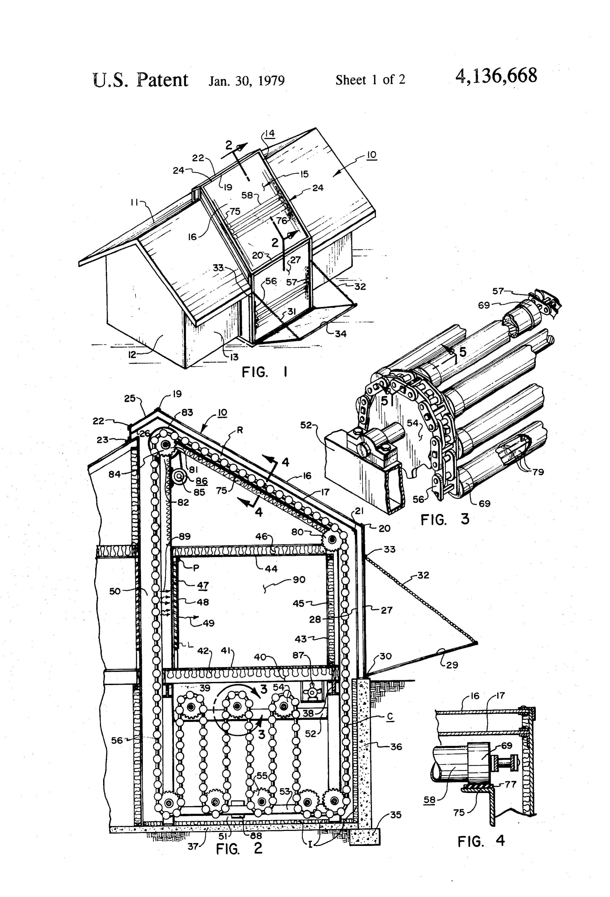
BRIEF SUMMARY OF THE INVENTION FIG. 1 is a perspective view of a building incorporat ing the heat storage system of the present invention.
According to the present invention, the underlying 50 FIG. 2 is an enlarged, fragmentary, vertical section and novel approach taken is to convey heat storage taken along the line 2-2 in FIG. 1.
means, including the series of containers thereof, from a FIG. 3 is an enlarged detail, fragmentary and in per storage and/or use area to the energy receptor area of a spective, of a representative one of the opposite sprock primary or ancillary building structure. In a preferred ets accommodating the mounting, at opposite ends, of form of the invention, a series of tubes containing heat- 55 the heat storage tubes, with their endless connectors; storage media are conveyed to a sunlight receptive area, the structure at FIG. 3 is typical of all the sprockets, for are automatically rotated about their individual axes example, that are used in the invention. during presence in such area, to obtain uniform heating FIG. 4 is an enlarged fragmentary section taken along of the heating tubes supplied; then the tubes are re the line 4-4 of FIG.3, illustrating the manner in which turned to a basement storage area for storage and utility. 60 a representative end of a representative heat storage It is, of course, impractical to convey a heat storage tube frictionally engages suitable means along its rails rock pile from the basement of the building to the roof for progressively rotationally advancing each respec and then back again. Furthermore, plumbing as afore tive tube as the same rolls downwardly along its rails mentioned is subject to possible malfunction and in underneath the translucent heat receptor structure of volves appreciable expense as well as heat transmission 65 the invention.
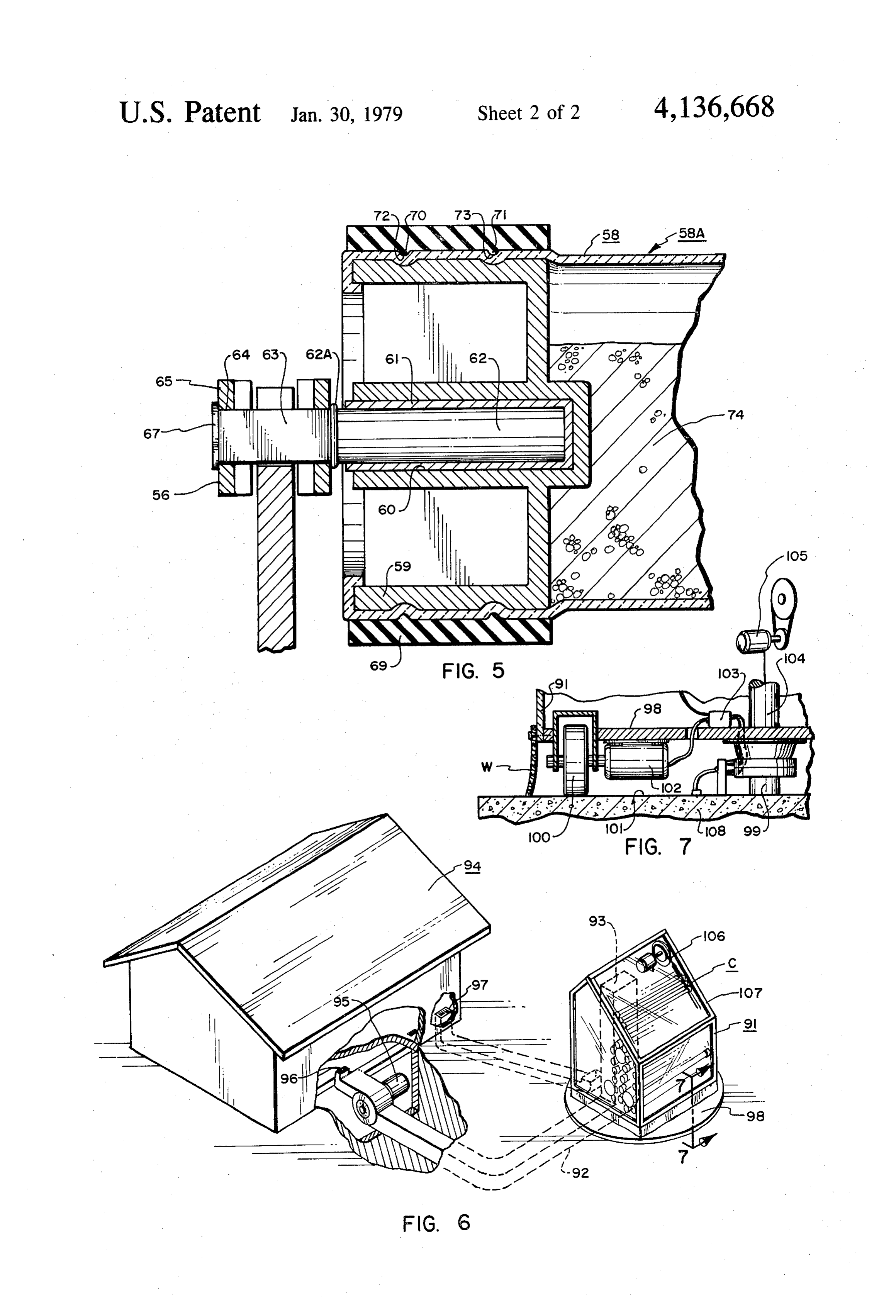
loss. FIG. 5 is an enlarged fragmentary vertical section In the present invention, the heat storage media en taken along the line 5-5 in FIG.3, and illustrates repre cased in movable tubes or other enclosures, is mechani sentative one of the opposite ends of the heat storage 5 tubes with their associated structure and endless con Oilite or other type of preferably self-lubricating bear veyors. ings 61. The bearing or bushing may simply be pressed FIG. 6 is a perspective view of a building including home in the aperture 60 as seen.
Journal shaft 62 is disposed in the bearing and in an auxiliary structure incorporating the heat collector and storage structure of FIG. 2. 5 cludes a raised medial annular protrusion 62A and also FIG. 7 is an enlarged fragmentary section taken along an outer end portion 63. The latter may assume any the lines 7-7 in FIG. 6, illustrating one means by which squared,within shape a preferred embodiment, e.g. simply or be of polygonal cross-section, for insertion the structure of FIG. 6 may be revolved periodically. in corresponding aperture 64 of a respective chain, e.g. DESCRIPTION OF PREFERRED 10 56, at a chosen link 65 thereof. The shaft end 67 can EMBODIMENTS simply be enlarged to provide for a retentive secure In FIG. 1 structure 10 forms an enclosure comprising ment of the journal shaft 62 relative to a respective a dwelling structure such as a residence, office building, chain heat 56. It will be understood that the opposite ends of or other utility or storage structure. The same will, of 15 each storage tube 58 will be secured to and sup course, include roof 11 and a series of sides such as at 12 ported by opposite sprocket chains 56, 57 in an identical and 13. A radiant energy receptor structure 14 is in ae.
A rubber or other elastomeric encasement or tire 69 cluded within the structure 10 and forms a sunlight can circumscribe each of the opposite ends of tube 58 receiving area 15, as defined by a series of translucent and can be secured in place by molded protrusions 70 panels 16 and 17 which are secured in place and and 71 disposed in annular slots 72 and 73 of the tube. mounted at structural angles 19-23. Angles 19-23 are 20 These slots may be formed actually by crimping the part of the rigid framework 24 which is secured to the tube onto roof and side structure for providing support for the site ends ofthesuch respective end bells 59 positioned at oppo tube. Each of the essentially rigid heat various translucent panels, not only at 16, 17, but also at storage means 58A, comprising the tubes 58 and their 25, 25, and 27, 28. The translucent panels may be, of course, of glass or any translucent plastic material. 25 respective associated structures, as shown, will gener Light reflective means 29 may comprise an aluminum ally includeand a heat storage medium as at 74. High heat panel reflector that is hinged by panel hinge 30 to the absorption stance of the heat storage can be obtained when the sub storage medium 74 will operate at its remainder of the structure. A pair of travel limit chains heat-of-fusion temperature, or in this range. One sub 31 and 32 are secured to framework structure 33 and the margin 34 of the light reflective means 29 so as to limit 30 stance that might be employed at 74 is a substance known as glauber salts, i.e. sodium sulfate decahydrate the latter's travel and appropriately position the panel (Na2SO4·10H2O) plus a crystalline agent such as borax, for proper receipt and reflection of sunlight from the or the substance known as Hypo, i.e. sodium thiosulfate exterior into region R that contains the heat collector or pentahydrate (Na2S2O2.5H2O) plus a crystallizing heat storage means hereinafter described. 35 agent, also such as borax.
Where the enclosure takes the form of a dwelling, see In a preferred form of the invention the radiant en FIG. 2, for example, then the same generally will in clude the usual foundation footings 35 and foundation ergy receptor structure 14 includes, underneath translu walls 36, one of each being shown. A slab 37 is poured cent panels 16, 17 a series of rails 75, 76 over which the heat storage tubes 58 will roll. The upper surfaces of in the usual way, insulation I is provided, and beams 38 these and 39 will be supported by the basement walls 36 in the face orrails 75, 76 will include a respective friction sur friction element 77, see FIG. 4 by way of exam usual manner. Floor joists 40 support flooring 41 which ple, which will frictionally engage the outer surfaces of is insulated from the underneath side by suitable batting opposite end cap 69, see FIG. 5, and thus cause the or other insulation material 42. The walls and ceiling as tubes 58 to revolve as they are advanced angularly at 43 and 44 are installed in the usual manner and insu lated by batting or other means at 45 and 46. The inner 45 downwardly, see FIG. 2. Thus, movement of the heat wall at 47 is louvered and may be fixed or made adjust storage tubes in the area of the translucent panels 16, 17 will be accompanied by an axial rotation of these tubes able by conventional pivotal louvered structure P as is so that these may present different surface sectors to the common with louvered or venetian blinds. The louvers
L are insulated where desired. In any event, there will 50 oncoming sunlight. This will measurably increase the be louver spaces 48 accommodating the reception of effectiveness sectors of the of the tubes so that all surface areas or area tube and the heat storage medium con radiant heat in the direction of the arrow 49 from the heat storage means 58A within travel space 50, further tained therein will be solar heated. hereinafter described. Where desired, each of the tubes, see FIG. 3, may be The basement area 51 will be provided with suitable 55 extruded to include inner radial fins 79, for example, see horizontal framework support means 52 and 53 for FIG.It3,istotoimprove heat conductivity to the tube interi journalling a series of sprockets 54 and 55 located at the ors. be noted that the fluid/crystalline substance at 74 is non-circulating, i.e. simply a stationary fluid various points, top and bottom, within the basement within the tube requiring no plumbing connection to area as shown. It will be observed that the sprockets as such tube.
at 54, 55 will be disposed in identical, horizontally In manner of assembly, for example, one of the end spaced, opposite side patterns, to accommodate the bells endless connectors 56 and 57, see FIGS. 1 and 2. These filled can be emplaced in a tube 58 and then the tube appropriately with the glauber salts or other solu endless connectors may comprise a pair of vertically tion; subsequently the remaining end bell is installed, oriented, mutually horizontally spaced sprocket chains, chains 56 and 57 being identical. These chains support 65 thus enclosing the eutectic substance. the rigid heat storage means 58A which, see FIG. 5, oneSuitable, being mutually horizontally spaced sprockets 80, shown in FIG. 2, are journalled and sup preferably comprise heat storage tubes 58 having end ported by fixed structure as at 52, for example, see bells 59 that may be machined or simply cast. End bell FIGS. 2 and 3, and are provided for advancing the 59 includes a central elongate aperture 60 receiving an
Page 6scan →
Eubes and their endless connectors in the manner shown ergy absorption is further enhanced by the provision of by the path arrows in FIG. 2. Likewise, a drive sprocket translucent panels 27, 28, these in conjunction with the 81 is journalled at the upper portion of framing 82 and light reflective means 29 provided. Tubes thus proceed includes an enlarged hub 83 which is coupled by belt 84 to the basement storage area at 51 where heat is stored to the drive 85 of drive motor 86. Accordingly, an 5 for transport to other occupancy areas either by virtue electrical circuit supply will be supplied the motor 86 of fan 87 or the upward transport of the tubes immedi for driving the connectors 56, 57 with their heat storage ately to the left of the louvered wall 47, supplying radi tubes connected to and disposed therebetween. It is ant heat at 89.
noted that all of the sprockets in the basement area of It is noted that the same operation will inhere in the FIG. 2 are so disposed that a serpentine configurement 10 ancillary structure at 91 in FIG. 6, but this kind of of the endless conveyors and their tubes at this point are blower will draw air from the structure 91 when needed routed in a serpentine configurement. This provides for and pump it into the house or other structure at 94. a maximum heat storage at this basement, or other heat In essence then, the present invention provides a storage region, without either interrupting unduly the means whereby the heat storage means, instead of re airflow or requiring an excessively large space for such 15 maining stationary as in the usual case, is actually heat storage. An electrically operated fan 87 and cold moved by virtue of the endless connectors and heat air-return 88 may be provided so that the fan serving as storage tubes described so that alternate portions of the a blower can either blow air or draw air from the base system are exposed to oncoming sunlight, with the ser ment area to heat desired portions of the dwelling. Ra pentine configurement at the bottom of the dwelling or diant heat energy as shown by the arrows 89 may pro 20 auxiliary structure, being operative to combine heat ceed through the spaces 48 of the louvered walls to storage to a small area in a manner as to offer the least supply radiant heat to a room area 90, see FIG. 2. These resistance to airflow.
louvers can be closed when desired by conventional The term "rigid' as applied to the heat storage means movable louver structure, abbreviated at P. or tubes is employed simply to differentiate from bare The entire system of sprockets, endless connectors, 25 fluid conveyance as by fluid pumping means, for exam and tube storage means in FIG. 2, may be designated ple, as used in the prior art.
simply as a heat collector and storage system C. It is of interest to note that the heat receiving and FIG. 6 illustrates that such storage system C can be storage system C is essentially weight-balanced, so that disposed in its entirety in a separate or auxiliary struc the sole energy required will be that needed to over ture 91, see FIG. 6, which will be supplied an insulated 30 come the friction of the support sprockets as at 54, 55. duct 92 and also a return duct 93, both being coupled to This is because the left-hand run of heat storage tubes at the dwelling structure 94 in the manner illustrated in area 50 is counterbalanced by the descending tubes at FIG. 6. A blower can be supplied as at 95 for connect area R in FIG. 2.
ing the ductwork 92 and drawing heated air there Throughout the description and claims herein, the through to suitable heat registers 96 in the dwelling. A 35 term "translucent' shall also comprehend and include cold air return at 97 will be connected to the ductwork "transparent'. It is also to be noted that the heat storage 93 to lead back into the structure 91 to complete the tubes, preferably having a dull, dark finish for maximum airflow circuit. light to heat conversion, need only be actuated intermit Where desired, structure 91 may be mounted on a tently, as desired, since they will amply heat, even on a rotatable support 98, the latter being journalled for 40 winter day, when they are stationary at the solar energy rotation on a fixed post 99 and provided with a roller or receptor area.
wheel 100 which rolls over the upper surface 101 of While particular embodiments of the invention have concrete support pad 108. Wiper W can be included. been shown and described, it will be obvious to those Motor 102 may be provided and mounted as shown to skilled in the art the various changes and modifications drive wheel 100 about its travel circle, the motor being 45 which may be made without departing from the essen connected through commutator means 103 to an electri tial features of the present invention and, therefore, the cal source 104. The latter also couples to motor 105 aim in the appended claims is to cover all such changes which drives the pulleys or hub 83, also found at the top and modifications as fall within the true spirit and scope of enclosure structure 91 by virtue of the former's inclu of the invention.
sion in system C. 50 I claim:
Accordingly, when desired, the auxiliary structure 1. In a building structure having an occupancy area, a can be used exterior to the house to provide the heat basement heat-storage area disposed at a level under required for the dwelling 94. neath said occupancy area, and an upper, radiant energy In operation, the system C collects heat from the receiving area, a pair of mutually spaced endless con sunlight (1) at panel areas 16, 17, see FIG. 2, and also 27, 55 nectors passing into and through said basement heat 28; where the auxiliary structure 91 is employed, (2) storage area and also circumscribing said occupancy through the translucent panels 106 enclosed at several area, a series of mutually spaced, elongate, heat storage areas in the framework 107 thereof. The heat storage elements interconnected to and between said endless means comprising the tubes 58 with their ancillary connectors, means for supporting for movement said structure collect heat and are conveniently moved via 60 endless connectors, and means for progressively driving the continuous or, generally, intermittent operation of said endless connectors whereby to advance said heat drive motor 86 in FIG. 2. It is to be noted that as the storage elements toward, proximate, and past said radi tubes move downwardly over their rails as at 75, 76 in ant energy receiving area.
FIGS. 1 and 2, the tubes are rotated so as to face other 2. The structure of claim 1 wherein said building surface sectors of the tubes to the oncoming sunlight. 65 structure includes translucent panelling essentially de Once the tubes are heated, then additional tubes are fining said radiant energy receiving area. advanced upwardly to take advantage of the receptor 3. The structure of claim 1 wherein said supporting area R and the incoming sunlight thereat. Radiant en means are mutually spaced in said basement area 7 whereby to define a serpentine configurement and radiant energy receiving area also communicating with travel path for said heat storage elements at said base said heat storage elements, and a light reflection means ent area. proximate said second, radiant energy receiving area. 4. The combination of claim 1 wherein said structure 7. The combination of claim 1 wherein said heat stor includes air current producing means disposed proxi 5 age elements are pivotally mounted to said endless con mate said heat storage elements in said basement area. nectors, said radiant energy receiving area including 5. The combination of claim 1 wherein said occu pancy area is provided with at least one louvered wall rails move onto and over which said heat storage elements in rolling contact.
proximate to and separating said heat storage elements 8. The structure of claim 7 wherein said endless ele
6. The combination of claim 1 wherein building struc ments comprise sprocketto chains, said heat storage ele ture includes a roof having translucent panel means ments being journalled sk said sprocket chains.
defining said radiant energy receiving area, a second
Provenance
- Collection
- Patents citing this work
- Pages
- 7
- Method
- pdftotext (the PDF's own text layer) + pdftoppm 300dpi page scans
- Patent office record
- patents.google.com →
- Source
- Google Patents citing-documents table
- Assignee
- Davis Ariel R
- Published
- 1979-01-30
- Transcribed from
- patentimages.storage.googleapis.com →