

patent · US4142512A
Solar vaporizing chamber
6 March 1979
Text
Page 1scan →
United States Patent (19)
Brown
(54) solar waporizing chamber
(76). Inventor: Darrell R. Brown, 2558 N.W. 19th St.,
Oklahoma City, Okla. 73107
51) Int. C.’................................................. F24J 3/02 52) U.S.C. ..................................... 126/271; 126/270
1,951,403 3/1934 Goddard . ... 60/641 1,969,839 8/1934 Goddard .... . . 126/271 2,259,902 10/1941 McCain ................................ 126/271 2,342,062 2/1944 Schenk ................................. 126/271
2,918,219 12/1959 MacCracken .......................... 237/64 3,008,297 1 1/1961 Plimpton, Jr. .. . 122/366X 3,556,124 1/1971 Walton ................................. 137/564 3,654,759 4/1972 Abbot .................................... 60/641 3,813,037 5/1974 Bekedam .... ... 237/67 X 3,940,058 2/1976 Norris ..... ... 237/67 X 4,033,134 7/1977 Bentley .................................. 60/641 Primary Examiner-William F. O'Dea
Assistant Examiner-Larry Jones
The present invention consists of a novel solar liquid vaporizing chamber for receiving liquids for vaporiza tion. Hot vapors are released from the chamber and piped to desired locations while additional liquids are introduced into the chamber for vaporization.
9 Claims, 14 Drawing Figures
Drawings
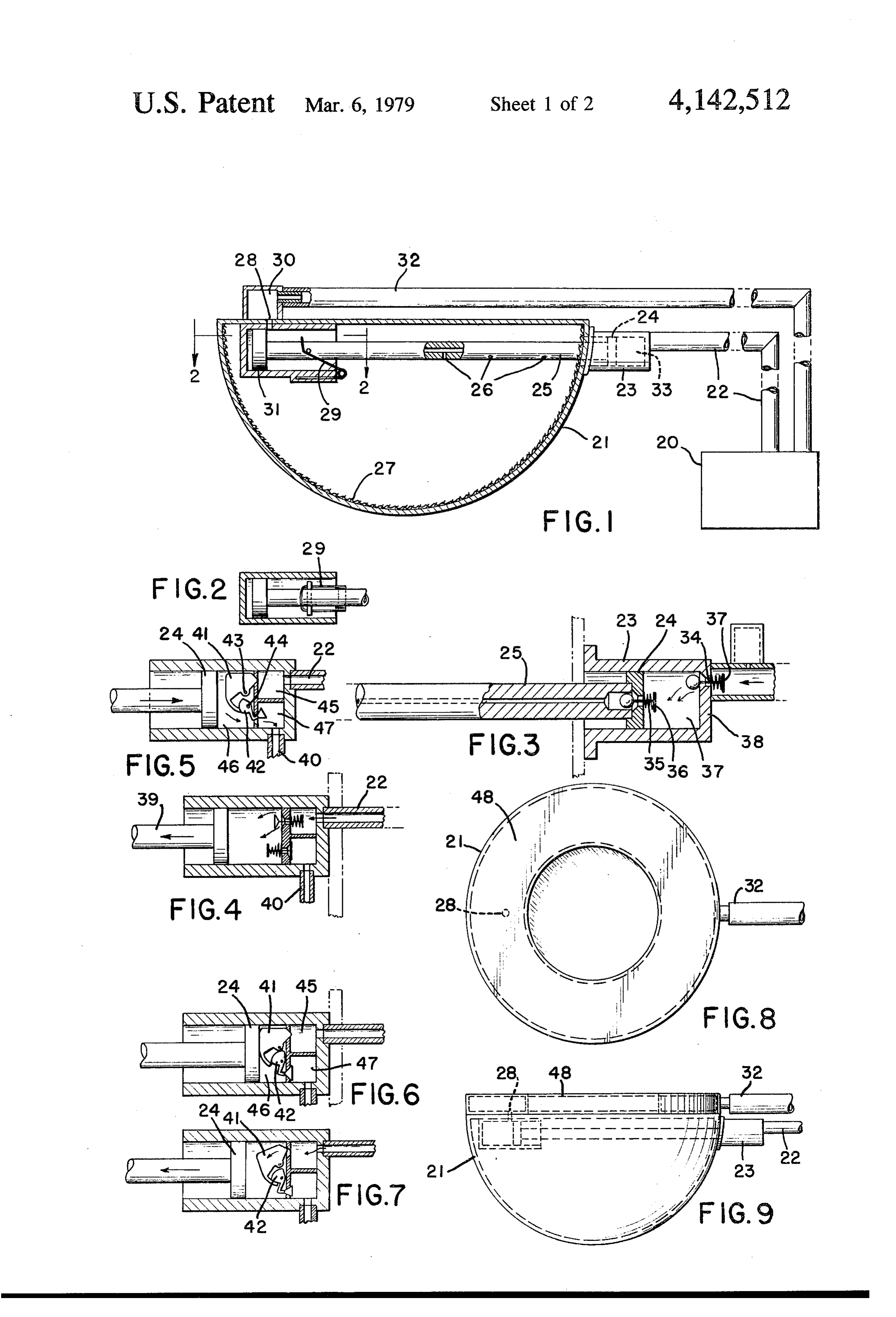
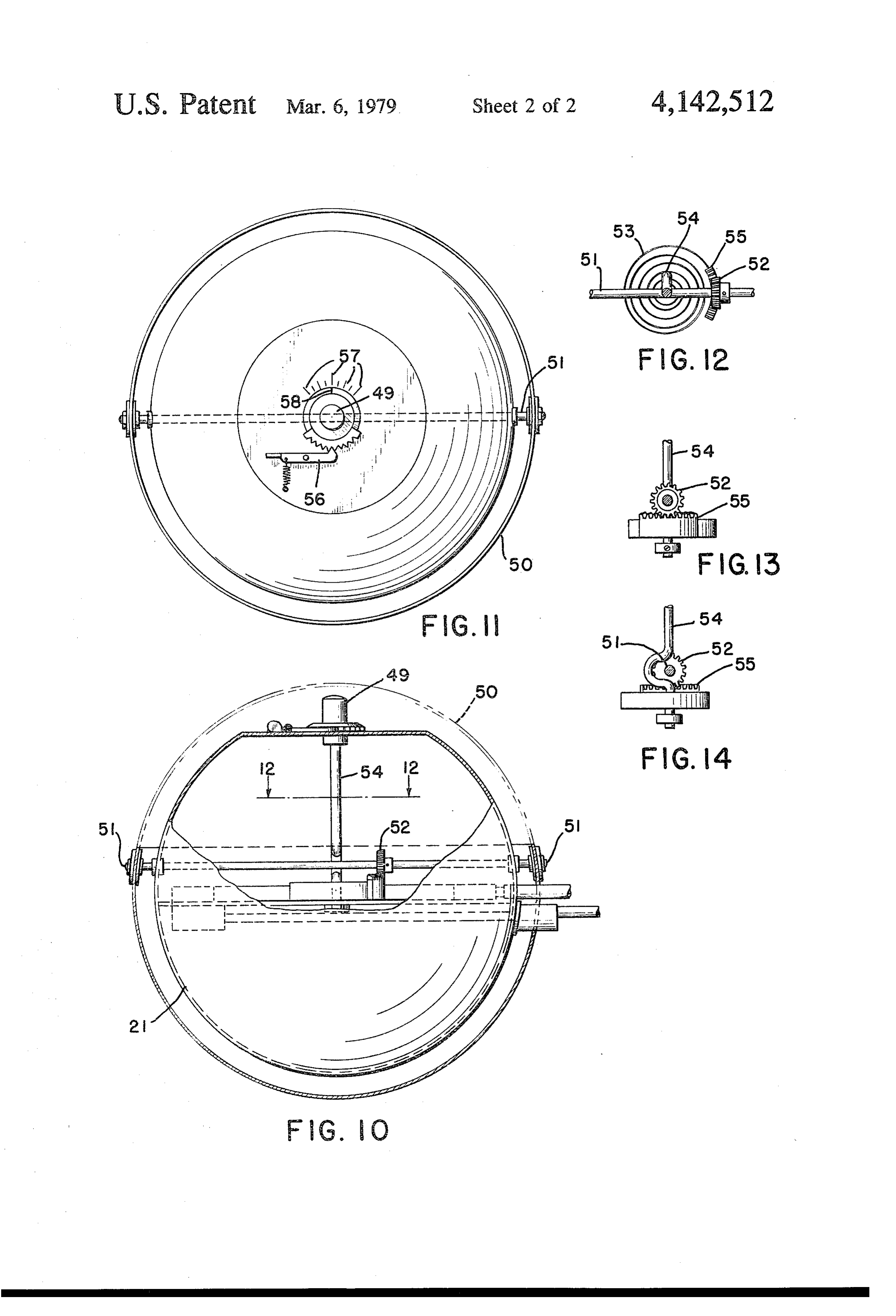
FIG. 12 is a top view of the thermostatic spring and 20 ber to flow through said valve and into the heating chamber 21. Valve feet 36 and 37 hold the check valves cover gearing arrangement.
Page 2drawing sheetscan →
Page 3drawing sheetscan →
Page 4scan →
Description of the drawings and
Solar vaporizing chamber preferred embodiment
Background and objectives of the
INVENTION s berThis invention consists of a liquid vaporizing cham which may be hemispherically shaped, though cy
There are three ways in which heat may be trans lindrical and flat plate types may also be utilized, ferred from a body of higher temperature to one of whereby the rays from the sun, reflected or direct, lower temperature: by radiation, by conduction or by strike the outer surface of the chamber and vaporize the convection. liquid contained therein. A liquid entry port and vapor The transmission of heat through space is known as 10 exit port is provided with suitable valve arrangements radiation and is governed by the same physical laws as whereby liquid introduced into the chamber is vapor in the radiation of light. For example, the sun's radiant ized, for example water may be vaporized into steam, energy is transmitted through space and heats the sur and the steam then passes through the exiting port and face of the earth. is directed to a desired location to be utilized, for exam Heat conduction is the passage from a body of higher 15 ple, in cooking.
temperature to another body at a lower temperature of As the rays of the sun strike the heating chamber, heat, which is brought in contact with it. For example, if pressure develops inside the chamber due to the increas a copper bar is heated at one end by an open flame, the ing temperature and forces the valve mechanism in heat will be conducted through the copper bar to the juxtaposition to the exit port to open, allowing the opposite end.
The present invention concerns the third method of steam a to enter the discharge pipes where it is directed to predetermined location away from the heating cham heat transmission, namely heat convection, which is the ber.
process of flowing a fluid over a solid surface accompa Various valve arrangements may be utilized which nied by a transfer of heat between the fluid and the allow the liquid entry port to open, allowing more liq surface. . 25
There are many devices known in the heating art taneously uid to be delivered to the heating chamber, while simul which use the convection method to heat homes and closing the vapor exiting port following es capement buildings. For example, steam boilers utilize this princi liquids employed. of the steam, or other vapors from suitable pal as hot water is converted to steam which passes liquid to enter the valve Such an arrangement would allow throughout the building in pipes to radiators which are 30 chamber to await entry into the positioned at strategic locations. The surfaces of the heating chamber, while simultaneously opening the radiators, after being heated by the steam, give off their vapor exiting port to allow escapement of the steam or heat to the cooler surrounding air. Hence a double other vapors from the heating chamber.
convection takes place, first in the steam heating the equipped In another embodiment, the heating chamber may be radiator, and secondly the radiator surfaces heating the 35 with a superheater to further heat the vapors cooler room air. after they exit from the heating chamber so that they Resistance coil heaters are also an example of the will remain free from suspended droplets of liquid. The convection type, in that the heated coil gives up its superheater consists of an additional chamber in which energy to the cooler surrounding room air, thereby the steam or vapor is subjected to additional radiation raising the temperature thereof. 40 by the sun absent contact with the liquid, thus raising With costs rising almost daily for energy production, the vapor's temperature without simultaneously raising newer, less expensive heating devices have been sought, its pressure to the saturation point.
many of which have utilized the energy generated by The solar heat generator can also be equipped with a the sun. solar radiation shield or cover which moves around the Conventional solar heating devices have been gener- 45 solar energy receiving portions of the generator, to ally difficult to regulate, and have been expensive to block or shield, partially or fully, the heating chamber construct and it is objective of this invention to con and any superheater from the rays of the sun. The cover struct a solar heating device in which the temperature can be thermostatically controlled so that as the heat can be easily regulated. inside the chamber approaches the desired temperature, It is another objective of this invention to provide a 50 the shield will revolve and limit the solar rays reaching solar heating system which can deliver heat down the heating chamber. Likewise, when the temperature wardly through a flexible pipe or other means more falls below a desired range in the heating chamber, the economically and faster than known methods. shield can rotate to a more open position allowing addi It is yet another objective of the present invention to tional provide a solar heating device which is relatively inex- 55 ber. Aenergy from the sun to reach the heating cham bimetallic coil in contact thermally with the pensive and economical to construct.
It is still another object of the present invention to generator could also be adapted to activate and control the movement of the shield.
provide a solar heating device with a superheater, to Turning now to the drawings, FIG. 1 represents a provide the heated fluids with additional energy to cross prevent premature condensation from occurring. 60 solar sectional heating view of the preferred embodiment of the chamber.
It is a further objective of this invention to provide a FIG. 2 is a top view of the vapor exiting valve uti solar heating system which has no secondary power lized in the preferred embodiment. source and therefore is economical and mobile. FIG. 3 shows the liquid entry valve arrangement It is yet another objective of this invention to provide a solar heating system which can deliver heated fluids 65 withFIG. a liquid passage contained inside the piston rod. 4 shows another embodiment of the liquid entry downwardly and while having the capability to retrieve and recycle said fluids without secondary power valve arrangement with the liquid passage being inde sources and without the use of capillary action, pendent of the piston rod.
Page 5scan →
FIG. 5 is yet another embodiment of the liquid entry from the reservoir 20 to the valve chamber 33, then valve arrangement showing a camming valve with the additional liquid is forced from said reservoir 20 bottom valve member open. through said conduit 22 into the valve chamber 33. FIG. 6 shows the valve arrangements of FIG. 5 with In FIG. 2 piston 31 is shown in its extended position, both the top and bottom valve members closed. whereby vapor exiting port 28 (not shown in FIG. 2) FIG. 7 shows the coming valve of FIG. 5 in still another position with the top portion of the camming awould be opened, and resilient member 29 would be in closed position.
valve open. FIG. 3 is an enlargement of the liquid valve arrange FIG. 8 demonstrates the top view of another embodi ment of the preferred embodiment and check valve ment of the solar heating chamber with a superheater O assemblies 34 and 35 are shown in their open positions positioned thereon. to allow water or other liquids to pass through them. As FIG. 9 is a cross sectional view of FIG. 8 showing the liquid piston 24 closes by moving away from heating positioned superheater above the liquid vaporizing chamber 21, as would happen immediately after the chamber.
liquid
FIG. 10 shows yet another embodiment of the heat 15 34 is closedin heating chamber 21 has vaporized, check valve ing chamber with a rotatable cover, thermostatically ber due to the compression of the valve cham controlled, positioned thereon. 33 and the resulting increase in pressure. Likewise, FIG. 11 is a top view showing the thermostat control the check valvepressure this increase in in the valve chamber 33 causes 35 to open and the liquid in said cham of FIG. 10
FIG. 12 is a top view of the thermostatic spring and 20 ber to flow through said valve and into the heating chamber 21. Valve feet 36 and 37 hold the check valves cover gearing arrangement.
FIG. 13 is a right side elevation view of FIG. 12. 35 and 34 in close proximity to their orifices so that the F.G. 14 is the left side elevation view of FIG. 12. minimum of fluid flows in the reverse direction as they For a more detailed description of the preferred em but are being closed. Springs are optional on these valves bodiment, referring to FIG. 1, liquid reservoir 20 is 25 potentialaid in closing them tightly and create a desirable shown positioned to supply liquids to vaporizing cham pressure drop from the foot side of the orifice ber 21 through liquid delivery pipe 22. Liquid entry to the ball or check side of it. As liquid piston 24 closes valve housing 23, connected to delivery pipe 22 is by moving away from heating chamber 21, as would shown mounted on heating chamber 21, Liquid can happen after all the liquid in heating chamber has va thereby pass through entry pipe 22, into valve housing 30 porized and escaped, check valve 35 opens and check 23, through piston 24 and continue into the hollow valve 34 is held closed due to the contact by liquid center or passageway of piston rod 25 for delivery into piston 24. Check valve 35 is opened by the increase in heating chamber 21 through liquid entry ports 26. pressure in valve chamber 33 due to the compression of Valve housing 23 and piston 24 may be so constructed chamber 33 by liquid piston 24. For safety purposes a to minimize thermal conduction from heating chamber 35 pressure regulating means in the form of a valve or 21 by spacially separating valve housing 23 and heating other device can be connected to the vaporizing cham chamber 21. The liquid is then diffused evenly through ber in the event that the pressure inside the chamber out heating chamber 21 by the capillary action of wick reaches a predetermined maximum, for example in the member 27. The rays of the sun that strike heating event that check valve 35 fails to open. chamber 21 will vaporize the liquid contained in wick 40 As liquid piston 24 closes by moving away from heat 27 creating a high pressure inside chamber 21. ing chamber 21, for example, immediately after liquid in As the pressure inside chamber 21 reaches the desired heating chamber 21 has all vaporized, check valve 34 is level, liquid piston 24 is urged towards heating chamber closed due to the compression of the valve chamber 33 21. and the resulting increase in pressure. This increase in Resilient member 29 is progressively less resistive as 45 pressure in the valve chamber 33 causes the check valve vapor piston 31 moves toward vapor exiting port 28, 35 to open and most of the liquid in said chamber to and as shown in FIG. 1, vapors are allowed to pass into flow through said valve and on into the heating cham exiting chamber 30 when vapor piston 31 clears vapor ber. The valve foot 36 prevents check valve 35 from exiting port 28. Vapor thus passing into exiting chamber flowing down piston rod 25 and the valve feet hold the 30 is directed into exit pipe 32 and is delivered to any 50 check valves in close proximity to their orifices so that desired location such as to a solar cooking stove (not a minimum of fluids flows in the reverse direction as shown). Condensate from a stove or other equipment they are closed. Springs or other resilient members are may be returned to liquid supply 20 for recirculation by optional but can help close the check valves and aid in gravity or with suitable pumping means (not shown). creating a desirable pressure increase from the foot side As the pressure decreases in heating chamber 21 due 55 of the orifice to the ball or check side of it. to the vapor escapement, resilient member 29 forces FIG. 4 demonstrates another liquid entry valve ar piston rod 25 to return to its previous position thereby rangement which may be used whereby piston rod 39 closing vapor exiting port 28. Liquid piston 24 is de does not have a hollow passageway through its center signed to force the liquid contained in valve chamber 33 to conduct the liquids entering heating chamber 21, but through piston rod 25 simultaneously with the closing 60 instead, piping member 40 is used to convey the liquid of vapor exiting port 28. Thus, a new vaporizing cycle into heating chamber 21.
begins whereby liquid enters heating chamber 21 and is In another embodiment of the liquid entry valve ar vaporized, causing vapor piston 31 to move past vapor rangement, as shown in FIG. 5, camming valve mem exiting port 28, which in turn allows liquid piston 24 to bers 41 and 42 rotate respectively about pivot members expand valve chamber 33, thus decreasing the pressure 65 43 and 44 to control the flow of liquid from delivery in chamber 33. When the pressure drop from the liquid pipe 22 for passage into heating chamber 21 through reservoir 20 to the valve chamber 33 is greater than the piping member 40. In FIG. 5, camming member 41 is pressure drop, if any, along liquid delivery conduit 22 shown in its closed position while camming member 42 6 is open to allow liquid to flow from chamber 46 into coil properly senses the temperature of the heating chamber 47 and continue into piping member 40. chamber 21 or superheater 48, when required. In FIG. 6, liquid piston 24 is shown in its closed posi In FIG. 13, rack member 55 is shown positioned for tion, abutting camming member 41 which in turn causes movement by spur gear 52 in either clockwise or coun camming member 42 to close. terclockwise direction.
In FIG. 7, liquid piston 24 is shown in a more open In FIG. 14, thermostat connecting rod 54 is shown position than in FIG. 6 whereby camming member 41 is having a U-shaped configuration on its lower end to open and camming member 42 is closed. bypass shaft member 51 to prevent interference as tem In another embodiment of the invention, liquids perature adjustment knob 49 is regulated by the opera which are vaporized in heating chamber 21 may be 10 tor to the desired setting.
subjected to additional heat by their passage through a Many variations and designs can be utilized which do superheater 48 as shown in FIG.8. As vapors exit the not alter the improvements contained herein, and such heating chamber 21 through vapor exiting port 28, they modifications and changes are considered to be within are then directed into superheater 48 which is posi 5 theI scope claim:
of this invention.
tioned so as to absorb additional solar radiation. The vapors become superheated and are then directed 1. A device for delivering solar heated fluids compris through vapor exiting pipe 32 and are conveyed to any ing: a solar heating chamber, a pressure releasable vapor desired location. The superheater 48 as shown in FIG.9 outlet means in communication with said chamber, a is positioned on top of the hemispherical heating cham fluid inlet means in communication with said chamber ber 21, although other designs and constructions may 20 for supplying vaporized fluids to said chamber, said solar energy vaporizing chamber including a thermo position the superheater in other locations.
In another embodiment, as shown in FIG. 10, the static regulating means, said regulating means including sun's rays reaching heating chamber 21 may be regu a chamber shield means, said shield means including a lated by a thermostat 49 which controls a shield or shaft and a rotatable shield mounted thereon for rota cover member 50. Shield 50 is rotatably mounted to 25 tion around said shaft.
cover or "block' the sun by shading the heating cham 2. A device for delivering solar heated fluids compris ber 21, or a portion thereof. Shield 50 pivots on shaft ing: a solar heating chamber, a pressure releasable vapor member 51 which is rigidly affixed to spur gear 52. outlet means in communication with said chamber, a Temperature adjustment knob 49 is connected to a fluid inlet means in communication with said chamber bimetallic coil member 53 by thermostat connecting rod 30 for supplying vaporizable fluids to said chamber, said 54. As adjustment knob 49 is rotated by the operator for fluid inlet means comprising a piston assembly, said a lower temperature setting, in a counterclockwise di piston assembly having a piston rod, said piston rod rection, coil 53 is tightened which results in spur gear 52 having an inner passageway with at least one port com rotating in a counterclockwise direction also. Shield 50 35 municating with said passageway and said chamber for then "lowers' or covers an additional portion of heat delivering fluids to said chamber whereby said vaporiz ing chamber 21 and prevents radiation from striking the able fluids are vaporized and exit from said chamber covered portion. Similarly, if a higher temperature is to through said outlet means.
be maintained within heating chamber 21, knot 49 is 3. A device for delivering solar heated fluids as turned in a clockwise direction which urges the bimetal claimed in claim 2, wherein said vapor outlet means is in lic coil 53 to expand causing clockwise movement of 40 communication with a downwardly directed piping rack member 55 which in turn causes spur gear 52 to means whereby said vaporized fluids are delivered rotate in a clockwise direction and causes shield 50 to downwardly.
"open" or move upwardly allowing additional radiation claimed 4. A device for delivering solar heated fluids as to strike heating chamber 21. in claim 2, wherein said outlet means and said Once set, temperature adjustment knob 49 and bime 45 inlet means are suitably connected whereby closing said tallic coil 53 will keep the heating chamber 21 function outlet means will open said inlet means. ing at the desired temperature range as long as the rays 5. A device for delivering solar heated fluids as from the sun or other external heating forces reach the claimed in claim 2, wherein said outlet means comprises chamber to vaporize the liquid. a piston assembly means.
Thermostat latch member 56 is shown in FIG. 11 50 6. A device for delivering solar heated fluids as along with thermostatgraduations 57. Latch member 56 claimed in claim 5, wherein said piston assembly means maintains temperature adjustment knob 49 at a desired is urged closed by a resilient member. 7. A device for delivering heated fluids as claimed in setting, and prevents slippage and inadvertent tempera ture settling changes. Thermostat indicator mark 58 is claim 2, and a pressure regulating means on said cham shown positioned midway of the graduations 57 in FIG. 55 ber,8. A device for delivering heated fluids as claimed in 11, and may be rotated clockwise or counterclockwise claim 2, and a wick means in said chamber. as desired.
In FIG. 12, shaft member 51 is shown mounted above 9. A device for delivering heated fluids as claimed in bimetallic coil 53, however, other designs may place claim 2, and including a super heater for receiving va shaft 51 below coil 53 and the exact placement of shaft 60 porized fluids from saidk heating chamber.
51 is a matter of choice by the builder, provided that the
Provenance
- Collection
- Patents citing this work
- Pages
- 6
- Method
- pdftotext (the PDF's own text layer) + pdftoppm 300dpi page scans
- Patent office record
- patents.google.com →
- Source
- Google Patents citing-documents table
- Assignee
- Brown Darrell R
- Published
- 1979-03-06
- Transcribed from
- patentimages.storage.googleapis.com →