

patent · US4144017A
Pulverized coal combustor
13 March 1979
Text
Page 1scan →
United States Patent (19)
Barsin et al.
(54) pulverized coal combustor
I75 Inventors: Joseph A. Barsin; David M. Marshall;
Edward A. Pirsh, all of Akron, Ohio 73) Assignee: The Babcock & Wilcox Company,
New York, N.Y.
51 Int. C.’................................................ F23L 9/00 (52) U.S. C. ...................................... 431/10; 431/160;
1,867,221 7/1932 Hepburn .......................... 431/1.75 X 2,275,394 3/1942 Hardgrove ......................... 110/28 E
3,048,131 8/1962 Hardgrove ........................ 431/10 X 3,730,668 5/1973 Iida et al. ............................... 431/10 3,856,455 12/1974 Otway et al. ...................... 431/10 X
3,890,084 6/1975 Voorheis et al. ...................... 431/10 4,013,399 3/1977 Craig et al. ...... ... 431/351 4,021, 186 5/1977 Tenner ................................... 431/10 4,021,188 5/1977 Yamigishi et al. ..................... 431/10 4,060,376 1/1977 Peredi ................................ 431/10 X 4,060,378 1 1/1977 Peredi................................ 431/10 X Primary Examiner-Edward G. Favors
Attorney, Agent, or Firm-J. Maguire; R. J. Edwards
An apparatus and method whereby fuel is burned in serially connected furnaces under controlled combus tion temperature and airflow conditions so as to inhibit the formation of nitric oxides while achieving complete combustion of the fuel.
7 Claims, 9 Drawing Figures
Drawings
Page 2drawing sheetscan →
Page 3drawing sheetscan →
Page 4drawing sheetscan →
Page 5scan →
ited by maintaining flame temperature at or below
Pulverized coal combustor 2,900 f
BACKGROUND OF THE INVENTION SUMMARY OF THE INVENTION The present invention relates to fuel firing and more 5 The present invention sets forth an apparatus and particularly to an arrangement for reducing the forma method whereby fuel is burned in serially connected tion of nitric oxides. .. furnaces under controlled combustion temperature and There is a present day growing concern with the airflow conditions to achieve a greater reduction in the immediate and long term problems created by the rapid formation of nitric oxide than has heretofore been possi increase in air pollution resulting from a rise in the 10 ble.
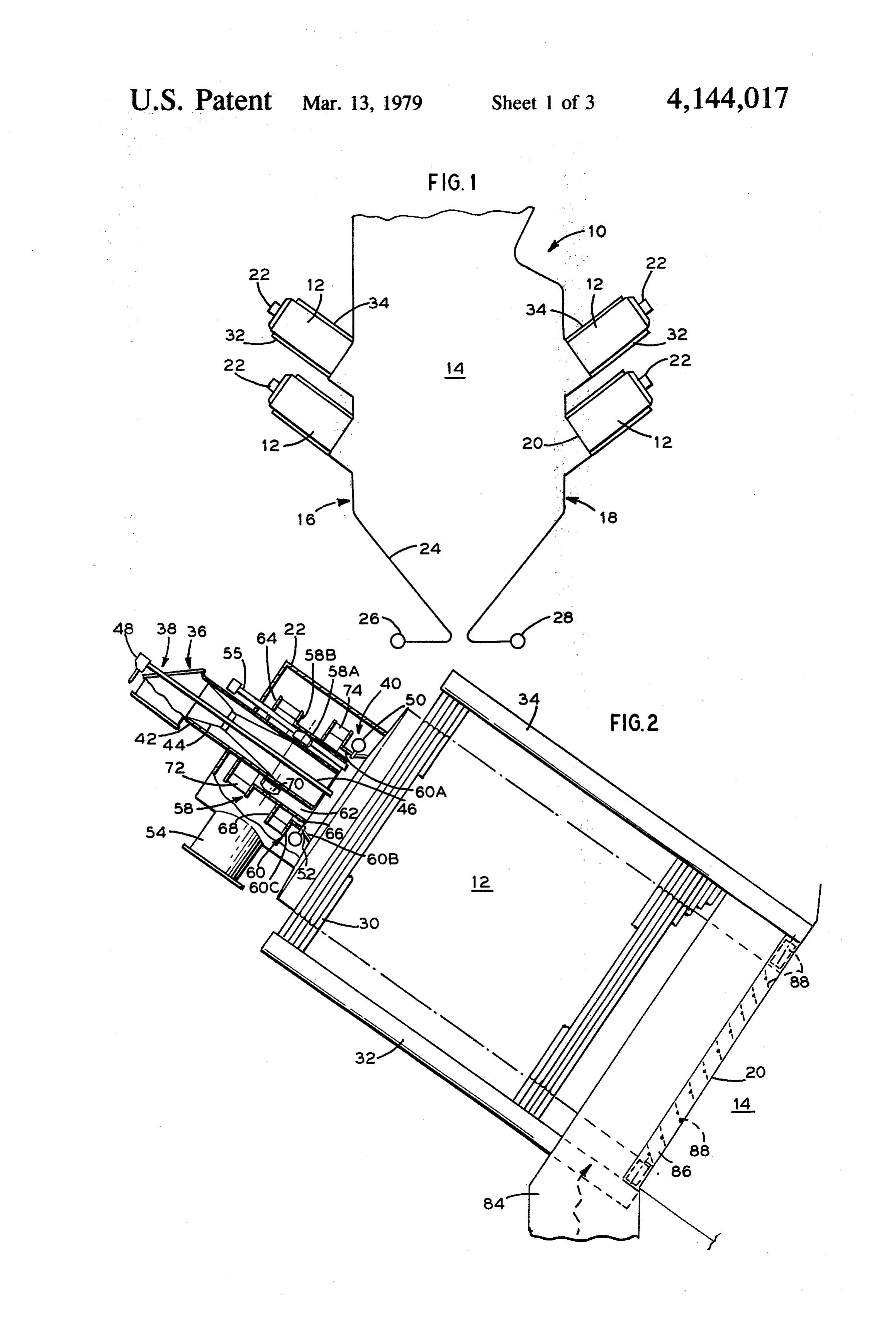
industrial civilization level throughout the world. With Accordingly, there is provided at least one fluid this concern comes an acute awareness that immediate cooled primary furnace and a fluid cooled secondary steps must be taken to reverse this upward trend in furnace. The primary furnace is formed with opposed pollution and great efforts are now being made by pub inlet and outlet openings, the inlet opening communi lic and private economic sectors to develop measures 5 cating with a plenum chamber and the outlet opening for preventing potentially polluting particles and gases communicating with the secondary furnace. The ple from being discharged into the atmosphere. One such num chamber admits fuel, combustion gas and air to the source of atmospheric pollution is the nitrogen oxides primary furnace. Diverse fuels are injected into the (NO) present in the stack emission of fossil fuel fired primary furnace through any one or a combination of steam generating units. Nitric oxide (NO) is an invisible, 20 burners. A common duct conveys the combustion gas relatively harmless gas. However, after it is discharged and air to the plenum chamber for delivery to the pri from the stack and comes into contact with oxygen, it mary furnace. A second duct delivers combustion air to reacts to form nitrogen dioxide (NO2) or other oxides of the secondary furnace at a location adjacent to the nitrogen collectively referred to as nitric oxides. Nitro primary furnace outlet. In an embodiment of the inven gen dioxide is a yellow-brown gas which, in sufficient 25 tion, the combustion gas and at least some of the com concentrations is toxic to animal and plant life. it is this bustion air delivered to the primary furnace is separated gas which may create the visible haze at the stack dis into controlled first and second streams wherein the charge of a vapor generator. first stream surrounds the second stream. With the advent of stricter emission controls, manufa The present invention includes a method whereby the curers of fuel burning equipment have been actively 30 combustion air delivered to the primary furnace is regu seeking techniques for limiting the amount of pollutants lated to introduce 50 to 70 percent of total stoichiomet which are formed from the combustion of fossil fuel. ric air to the primary furnace while maintaining the Such techniques are disclosed in U.S. Pat. Nos. maximum combustion temperature at or below 2500' F. 3,788,796; 3,880,570 and 3,904,349 assigned to the As The combustion air delivered to the secondary furnace signee of the present invention. 35 is regulated to introduce 50 to 70 percent of total stoi Nitric oxide is formed as a result of the reaction of chiometric air to the secondary furnace while maintain nitrogen and oxygen and may be fuel derived nitric ing combustion temperature at or below 2900 F. The oxide and/or thermal nitric oxide. The former occurs total quantity of combustion air supplied to both the from the reaction of the nitrogen contained in the fuei primary and secondary furnaces is maintained in the with the oxygen in the combustion air whereas the 40 range of 105 to 125 percent of total stoichiometric air. latter results from the reaction of the nitrogen and oxy Recirculated combustion gas may be delivered to the gen contained in the combustion air. primary furnace to help maintain primary and second The rate at which fuel nitric oxide is formed is princi ary furnace maximum combustion temperature at or pally dependent on the oxygen supply in the ignition below the prescribed limits. During the firing of air zone. No appreciable nitric oxide is produced under a 45 conveyed pulverized coal, the conveying air comprises reducing atmosphere; that is, a condition where the 15 to 30 percent ot total stoichiometric air. In the em level of oxygen in the ignition zone is below that re bodiment which separates the combustion gas and air quired for a complete burning of the fuel. Under these delivered to the primary furnace into first and second conditions, the fuel nitrogen compounds are decon streams, the first stream is regulated to provide approxi posed and will not produce nitric oxide in further stages 50 mately 60 to 70 percent of the separated combustion gas of air supply within regulated temperature levels. and air with the remaindergoing to the second stream. The rate at which thermal nitric oxide is formed is BRIEF DESCRIPTION OF THE DRAWINGS dependent upon any or a combination of the following variables; (1) flame temperature, (2) residence time of FIG. is a schematic sectional elevation view of a the combustion gases in the high temperature Zone and 55 vapor generator embodying the invention. (3) excess oxygen supply. The rate of formation of nitric FIG. 2 is a sectional elevation view of the primary oxide increases as flame temperature increases. In vapor furnace associated with a dual register burner adapted generators of the type hereunder discussion wherein the to fire coal and/or oil and/or natural gas. combustion of fuel and air may generate flame tempera FIG. 3 is a top view of the primary furnace. tures in the order of 3,700 F., the time-temperature 60 FIG. 4 is a rear end view of the primary furnace. relationship governing the reaction is such that at flame FiG. 5 is a partial view of the primary furnace associ temperature at or below 2,900 F. no appreciable nitric ated with a dual register burner adapted to fire synthetic oxide (NO) is produced, whereas above 2,900 F. the or low B.T.U. gas.
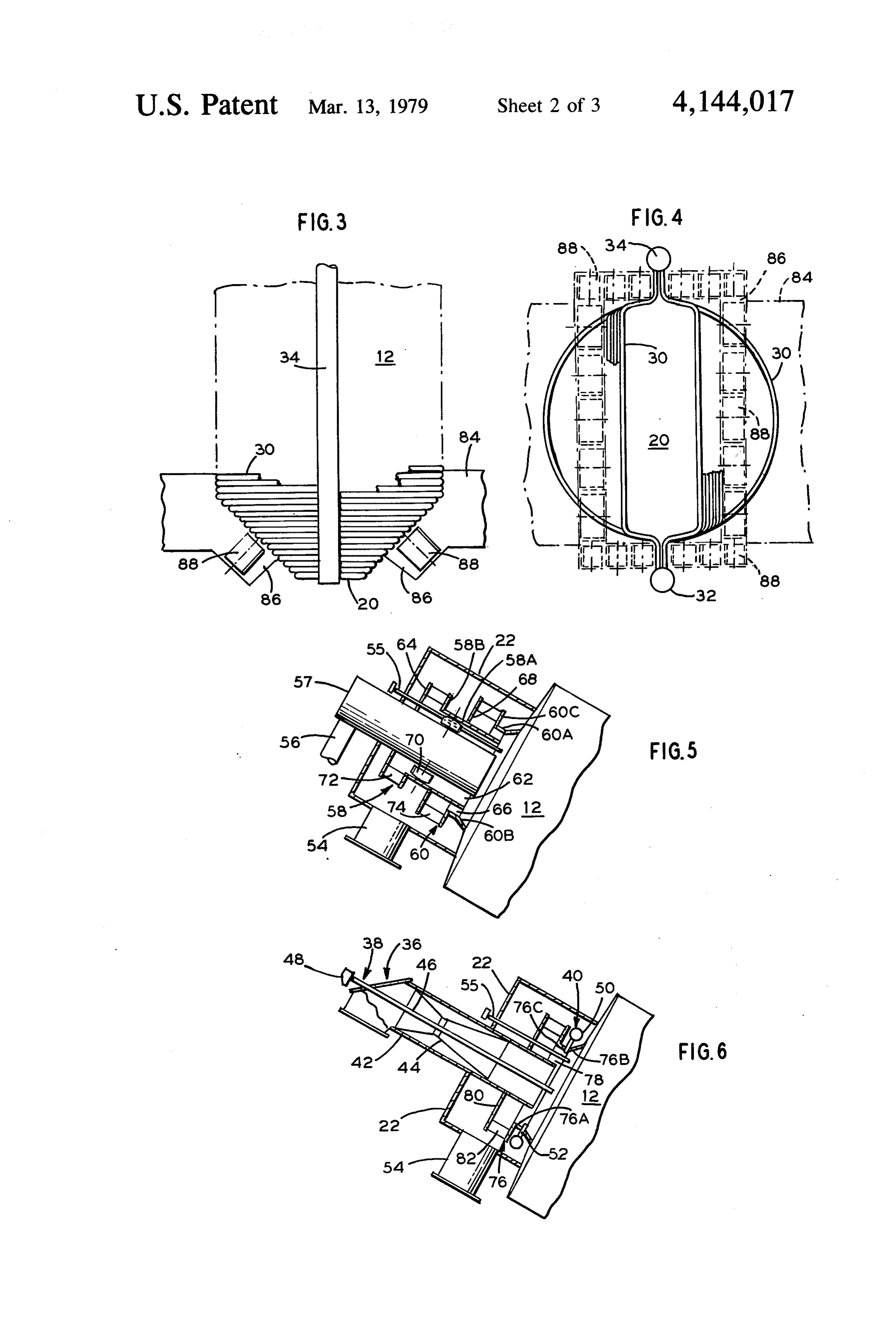
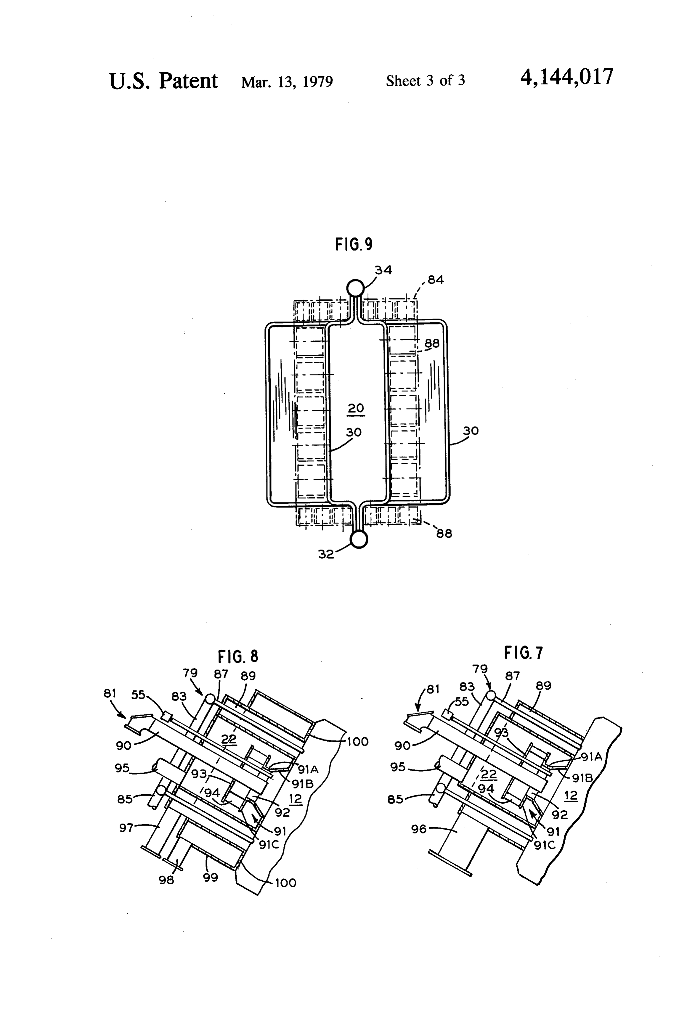
rate of reaction increases rapidly. FIG. 6 is a partial view of the primary furnace associ Thus, one will recognize from the foregoing discus 65 ated with single register burner adapted to fire coal sion that the formation of nitric oxide from fuel nitrogen and/or oil and/or natural gas. is inhibited by maintaining a reducing atmosphere, and FIG. 7 is a partial view of the primary furnace associ the formation of nitric oxide from air nitrogen is inhib ated with main and pilot burners adapted to fire coal.
Page 6scan →
FIG. 8 is an alternate embodiment of FIG. 7 includ related nozzle to form a second annular passageway 62 ing a separate introduction of recirculated combustion therebetween. A plurality of vanes 70 are disposed gas to the primary furnace. within the passageway 62 in surrounding relation to the FIG. 9 is a rear end view of an alternate embodiment related nozzle. The vanes 70 are equidistantly spaced of the primary furnace. and preferably interconnected through a linkage train,
Description of the preferred
not shown, so as to be collectively and simultaneously
Embodiments
adjustable. A plurality of equidistantly spaced register blades 72 and 74 are located at the respective inlet ends
Referring to FIGS. 1 and 2, there is shown a vapor of passageways 62 and 66. The register blades 72 and 74 generator 10 including fluid cooled walls which define 10 are adapted to pivot between open, closed and interme a plurality of primary furnaces 12 of circular cross-sec diate positions and are preferably interconnected tion and a secondary furnace 14 of rectangular cross through a linkage train, not shown, so as to be collec section. The front and rear walls 16 and 18 of the sec tively and simultaneously adjustable. ondary furnace 14 have portions thereof accommodat Referring to FIG. 6, the burner assembly shown ing the downwardly sloped primary furnaces 12 whose 15 therein is equipped with a single air register which is respective outlets 20 discharge into the secondary fur comprised of a sleeve member 76 disposed within the naces 14. A plenum chamber 22 is provided at the front plenum chamber 22 to discharge combustion air and end of the primary furnaces 12. Fluid is supplied to the recirculated combustion gas at the inlet to the primary tubes 24 of the front and rear walls 16 and 18 through furnace 12. The sleeve member 76 has a portion thereof the lower headers 26 and 28, and to the tubes 30 of the 20 76A concentrically spaced about the nozzle 42 to form primary furnaces 12 through the lower headers 32. The an annular passageway 78 therebetween. The remainder primary furnace tubes 30 are connected for discharge of of sleeve member 76 comprises a flared outlet 76B, and fluid to the upper headers 34. The outside surfaces of a flange 76C which is axially spaced from an annular the primary and secondary furnaces 12 and 14 are cov plate member 80 to form the inlet to passageway 78. A ered with insulation and sheet metal casing. The fire 25 plurality of equidistantly spaced register blades 82 are side of the secondary furnace 14 is generally bare as is located at the inlet end of passageway 78. The register that of the primary furnaces 12 equipped for only gas blades 82 are adapted to pivot between open, closed and and oil firing. Primary furnaces 12 equipped for coal intermediate positions and are preferably intercon firing will normally have the fire side studded and cov nected through a linkage train, not shown, so as to be ered by a layer of refractory material. 30 collectively and simultaneously adjustable. Referring to FIGS. 2 and 6, there is shown a primary Referring to FIGS. 7 and 8, there is shown a primary furnace 12 equipped with a pulverized coal burner 36, furnace 12 equipped with a pulverized coal burner 79 an oil burner 38 and a natural gas burner 40. Each of the and a pulverized coal-fired pilot burner 81. The coal burners is adapted so that it can be fired alone or in burner 79 includes a ring-shaped inlet manifold 83 that combination with one or both of the other burners. The receives pulverized coal from a supply pipe 85 and is coal burner 36 includes a discharge nozzle 42 fitted with fitted with a plurality of nozzles 87 which extend a venturi section 44. The oil burner 38 includes a barrel through an annular duct 89 to discharge coal into the section 46 having its inlet end fitted to a yoke assembly primary furnace 12. The pilot burner 81 includes a noz 48. The gas burner includes a ring-shaped inlet manifold zle 90 centrally disposed within the plenum chamber 22 50 formed with nozzles 52 discharging into the inlet of 40 and discharging to the primary furnace 12. The pilot the primary furnace 12. A common duct 54 delivers burner 81 is shown here as equipped with a single air combustion air and recirculated combustion gas to the register, however, it is equally adaptable to a dual air plenum chamber 22 for discharge to the primary fur register. The single air register comprises a sleeve mem nace 12. An ignition device 55 is provided to light the ber 91 which has a portion thereof 91A concentrically fuel or fuels being injected into the primary furnace 12. 45 spaced about the nozzle 90 to form an annular passage Referring to FIG. 5, there is shown a primary furnace way 92 therebetween. The remainder of sleeve member 12 equipped with a synthetic or low B.T.U. gas burner 91 comprises a flared outlet 91B, and a flange 91C which includes a discharge nozzle 57 receiving fuel which is axially spaced from an annular plate member from a supply pipe 56. The duct 54 delivers combustion 93 to form the inlet to the passageway 92. A plurality of air and recirculated combustion gas to the plenum 50 equidistantly spaced register blades 94 are located at the chamber 22. Lighting of the fuel is effectuated with the inlet end of passageway 92. The register blades 94 are ignition device 55. adapted to pivot between open, closed and intermediate Referring to FIGS. 2 and 5, the burner assemblies positions and are preferably interconnected through a shown therein are equipped with dual air registers. linkage train, not shown, so as to be collectively and Each dual air register is comprised of sleeve members 55 simultaneously adjustable. A supply duct 95 delivers 58 and 60 disposed within the plenum chamber 22 to combustion air to the plenum chamber 22 for discharge discharge combustion air and recirculated combustion through the register to the primary furnace 12, Lighting gas to the inlet of the primary furnace 12. The sleeve of the coal is effectuated with the ingition device 55. member 60 has a portion thereof 60A concentrically Referring to FIG. 7, there is shown a common duct spaced about the portion 58A to form a first annular 60 96 connected to the annular duct 89 and supplying com passageway 66 therebetween. The remainder of sleeve bustion air and recirculated combustion gas thereto for member 60 comprises a flared outlet 60B, and a flange discharge to the primary furnace 12. 60C which is axially spaced from an annular plate mem Referring to FIG. 8, there is shown a duct 97 con ber 68 to form the inlet to passageway 66. The sleeve nected to the annular duct 89 and supplying combustion member 58 has a portion thereof 58A concentrically 65 air thereto for discharge to the primary furnace 12, and spaced about the nozzle 42 of the coal burner depicted a duct 98 supplying combustion gas to an annular duct in FIG. 2, and the nozzle 57 of the gas burner depicted 99 for discharge to the primary furnace 12 through a in FIG. 5. The sleeve portion 58A cooperates with the plurality of circularly spaced openings 100,
Page 7scan →
Referring to FIGS. 2, 3, 4, and 9, there is shown the gas, whenever required, is introduced by duct 96 and is inlet header 32 which supplies fluid to the tubes. 30 regulated to equal 10 to 30 percent of the total weight lining the primary furnace 12, and the outlet header:34 flow of combustion air supplied to both the primary and which receives the fluid discharging from the tubes. 30. secondary furnaces.
A duct 84 delivers combustion air directly to the sec In the embodiment shown at FIG. 8, the combustion ondary furnace 14 through an outlet 86 disposed in air for the main burner 79 is supplied by duct 97 and the surrounding relation to the outlet 20 of the primary combustion gas, whenever required, is supplied by duct furnace 12. The combustion air duct outlet 86 houses a 98 through the annular duct 89 for discharge through plurality of damper blades 88 which are adapted to openings 100.
pivot between open, closed, and intermediate positions 10 While in accordance with the provisions of the stat and are preferably interconnected through a linkage utes there is illustrated and described herein a specific train, not shown, so as to be collectively and simulta embodiment of the invention, those skilled in the art neously adjustable. will understand that changes may be made in the form Referring to FIGS. 4 and 9, there is shown alternate of the invention covered by the claims and that certain embodiments of the invention wherein the primary 15 features of the invention may sometimes be used to furnace of FIG. 4 is of generally circular cross-sectional advantage without a corresponding use of the other flow area, and the primary furnace of FIG. 9 is of gener features.
ally rectangular cross-sectional flow area. The embodiments of the invention in which an exclu During operation of the invention, the combustion air sive property or privilege is claimed are defined as delivered to the primary furnace 12 is regulated to 20 follows:
maintain 50 to 70 percent of total stoichiometric air to 1. A method for inhibiting the formation of nitric the primary furnace, and the remainder of the combus oxides when burning pulverized coal, and including at tion air comprising 50 to 70 percent of total stoichiomet least one primary furnace having inlet and outlet open ric air is delivered to the secondary furnace 14. When ings, a secondary furnace in receiving communication ever required, recirculated combustion gas may be de 25 with the outlet opening, and comprising the steps of: livered to the primary furnace 12 to maintain the maxi introducing combustion air and pulverized coal mum combustion temperatures in the primary and sec through the primary furnace inlet opening, ondary furnaces at or below 2500 F. and 2900 F., regulating the combustion air to introduce 50 to 70 respectively. The combustion gas delivered to the pri percent of total stoichiometric air to the primary mary furnace is regulated to equal 10 to 30 percent of 30 furnace, said combustion air including air for con the total weight flow of combustion air supplied to both veying the pulverized coal to the primary furnace, the primary and secondary furnaces. maintaining the coal-conveying air at 15 to 30 percent In the embodiments shown at FIGS. 2 and 5, the of total stoichiometric air, combustion air supplied to the primary furnace 12 by introducing combustion air to the secondary furnace, the duct 54 is separated into first and second streams, 35 regulating the last named combustion air to introduce with the first stream flowing through passageway 66 50 to 70 percent of total stoichiometric air to the and the second stream through passageway 62. The secondary furnace, and streams are individually regulated by register blades 72 controlling the first and second named regulating and 74 so that the first stream will comprise 60 to 70 steps to maintain the total quantity of combustion percent of the combustion air being supplied by duct 54, 40 air supplied to said primary and secondary furnaces with the remainder going to the second stream. It in the range of 105 to 125 percent of total stoichio should be understood that whenever combustion gas is metric air.
supplied by duct 54, the distribution of combustion gas 2. The method according to claim 1 including the step as first and second streams will be the same as that of the of providing first and second burner means communi combustion air. The vanes 70 are adjustable to impart a 45 cating with the inlet opening for introducing the air rotational component to the combustion air and gas conveyed coal to the primary furnace.
flowing through the passageway 62. 3. The method according to claim 2 including the step In the embodiments shown at FIGS. 2 and 6, the of maintaining the coal-conveying air to the first burner combustion air used to convey pulverized coal to the means at 2 to 8 percent of total stoichiometric air. burner 36 comprises 15 to 30 percent of total stoichio 50 4. The method according to claim 2 including the step metric air. The remainder of the combustion air in of introducing 4 to 12 percent of total stoichiometric air tended for the primary furnace 12 is supplied by duct 54 around the outlet of said first burner means. and delivered through passageways 62 and 66 for the 5. The method according to claim2 including the step embodiment of FIG. 2, and passageway 78 for the em of maintaining the coal-conveying air to the second bodiment of FIG. 6. 55 burner means at 13 to 22 percent of total stoichiometric In the embodiments shown in FIGS. 7 and 8, 12 to 20 a1.
percent of the pulverized coal is fired through the pilot 6. The method according to claim 2 including the step burner 81 and the remainder is fired through the main of introducing 20 to 40 percent of total stoichiometric burner 79. The following percentage distributions of air around the outlet of said second burner means. combustion air delivered to the primary furnace is based 60 7. An apparatus for inhibiting the formation of nitric on total stoichiometric air: 2 to 8 percent used to con oxides when burning fuel, and comprising a plurality of vey pulverized coal to the pilot burner 81; 4 to 12 per primary furnaces having respective inlet and outlet cent supplied by duct 95 through the plenum 22 and openings, a secondary furnace in receiving communica passageway 92 as combustion air for the pilot burner 91; tion with the outlet openings, the primary and second 13 to 22 percent used to convey pulverized coal 65 ary furnaces being lined with fluid cooled tubes, means through inlet 85 to the main burner 79; and 20 to 40 for introducing fuel and combustion air through the percent supplied by duct 96 through the annular duct 89 respective primary furnace inlet openings, means for as combustion air for the main burner 79. Combustion regulating the combustion air to introduce 50 to 70 .
Page 8scan →
percent of total stoichiometric air to the primary fur second named regulating means being controlled to naces, means for introducing combustion air to the sec maintain the total quantity of combustion air supplied to ondary furnace, means for regulating the last named said primary and secondary furnaces in the range of 105 combustion air to introduce 50 to 70 percent of total to 125 percent of total stoichiometric air. stoichiometric air to the secondary furnace, the first and 5
Provenance
- Collection
- Patents citing this work
- Pages
- 8
- Method
- pdftotext (the PDF's own text layer) + pdftoppm 300dpi page scans
- Patent office record
- patents.google.com →
- Source
- Google Patents citing-documents table
- Assignee
- The Babcock & Wilcox Company
- Published
- 1979-03-13
- Transcribed from
- patentimages.storage.googleapis.com →