

patent · US4147157A
Self-supporting active solar energy system
3 April 1979
Text
Page 1scan →
United States Patent (19)
Zakhariya
(54) self-supportng active solar
Energy system
76) Inventor: Ramiz H. Zakhariya, 2400 McBride (51) Int. C.’................................................. F24, 3/02 (52) U.S. C. .................................. 126/271; 136/89 P;
(58) Field of Search ........................... 136/89 P, 89 R;
1,849,266 3/1932 Bentz .................................... 126/271 3,974,822 8/1976 Patil .......... a a & 126/271
4,026,267 5/1977 Coleman ............................. 126/271
Primary Examiner-John J. Camby
Assistant Examiner-Larry I. Schwartz
Attorney, Agent, or Firm--Melvin R. Stidham
An active solar energy system comprising an array of solar collectors, a pumping device to circulate fluid therethrough and a storage tank to contain the heated fluid. The pump is driven by an electric motor and a solar-electric power transducer system energizes the motor, whereby the fluid is circulated through the col lector system whenever sunlight is available. The heated fluid from the collector array, as well as the unheated fluid from the source are delivered to a mixing vessel from which the mixture fluid is delivered to a storage tank to meet demands.
2 Claims, 1 Drawing Figure
Drawings
Page 2drawing sheetscan →
Page 3scan →
preheats inlet fluid, but functions as an expansion ac
SELF-SUPPORTNG ACTIVE SOLAR ENERGY commodation chamber, a storage tank and a distribu SYSTEM tion center for circulation of fluid through lines 24 and BACKGROUND OF THE INVENTION 30 from lines 18 and 21. Further, with modification it 5 could function as a heat exchanger when a non-freezing
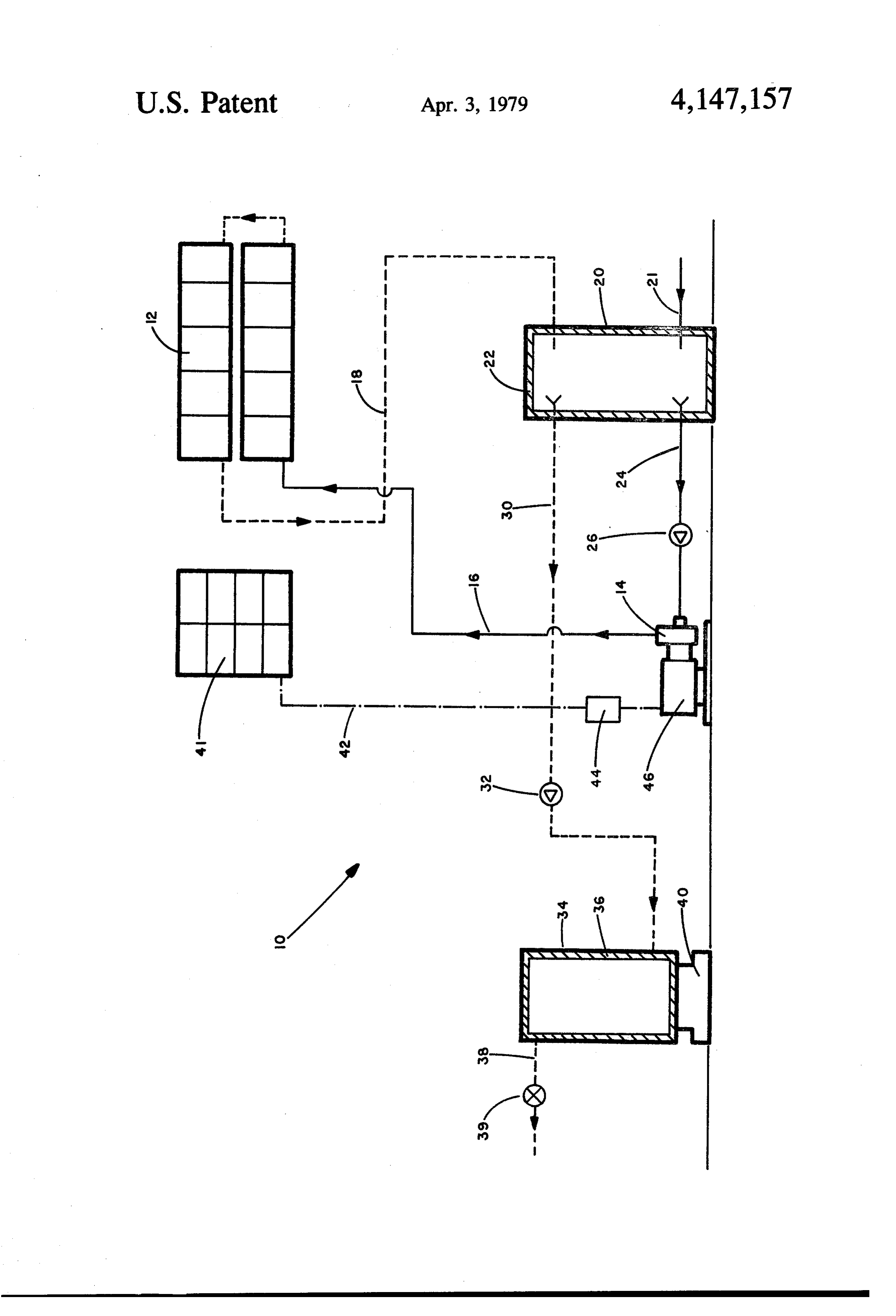
In active solar energy systems presently available, a liquid is circulated through the solar collectors 12. fluid is circulated through solar collectors by some The mixer vessel is also thermally insulated at 22 to mechanical means using conventional sources of en maintain a level of heat achieved. Colder fluid from the ergy, such as commercial electricity for energizing mixer tank is drawn by the pump 14 through a ther motor driven pumps. Such systems generally include 10 mally insulated conduit 24, with a suitable one-way electric and electronic control devices which are rela valve 26 therein to prevent backflow. tively expensive and also depend upon utility power for The warmer fluid is forced from the mixer tank 20 their energy requirements, thereby increasing the cost through thermally insulated conduit 30 and one-way of operation as well as that of acquisition. valve 32 to one or more suitable storage tanks 34, also 15 thermally insulated at 36. The fluid as needed for con
OBJECTS OF THE INVENTION sumption is drawn off through thermally insulated duct It is an object of this invention to provide an active 38 by operation of suitable valve means 39, such as a solar energy system which is not dependent upon the water tap when water is the medium.
purchase of energy for operation. If desired, the system may be supplemented with a It is a further object of this invention to provide a 20 thermostatically controlled heater 40 on one or more of solar energy system which is relatively inexpensive to the storage tanks.
install and which may be operated at little or no cost. Photovoltaic panels or solar-electric transducer 41 in Further objects and advantages of this invention will size and number depending upon the capacity and out become apparent from the description to follow, partic put of the system 10, generate electricity on solar expo ularly when read in conjunction with the accompany 25 sure which is conducted at 42 through associated circui ing drawing. tary 44, if required, to a motor 46 which drives the SUMMARY OF THE INVENTION pump 14. Hence, when sun is available, the motor 46 is energized and pump 14 circulates fluid through the
In carrying out this invention, I provide an array of solar panels 12 to the mixer tank 20 with the colder fluid solar collectors through which a fluid, either liquid or 30 from the input line 21 being drawn to the pump. The gas, is circulated. In the case of water, for example, as a pressure of fluid in the source system 21 is sufficient to medium, it is delivered to the system from a utility force fluid from the mixer vessel 20 through the line 30 water line to be pumped through the array of solar to the storage tanks 34.
collectors and into a mixing vessel where it mixes with, The operation of this system 10 may be described as and preheats the source fluid. From the mixing vessel 35 follows:
the fluid is passed to a storage tank or tanks from which When sun is available and heated fluid is in demand, it is drawn off as needed. The pump is driven by an the photovoltaic panels will energize the motor 46 to electric motor which is energized from an array of drive the pump 14 and circulate fluid through the col photovoltaic panels or solar-power transducers so that, lector panels 12, whereby the heated fluid will be mixed when sun is available, the circulation of the fluid 40 to preheat water in the mixer vessel from the source 21, through the collector panels is continual without reli and is then passed to the storage tanks 34 and out ance upon an external electrical source. When there is through lines 38 to meet the demand. no demand, the circulation through the collector array When sun is not available and fluid is in demand, the continues to elevate the temperature in the mixing ves motor 46 is inactive and, hence, there is no flow through sel which should be of adequate capacity to handle 45 the solar collectors 12. Only the fluid existing in the demands. The solar heating capacity may be supple mixer vessel 20 and the main storage tank 34 is heated mented by a thermostatically controlled heater at one for use, and it could occur that unheated fluid is eventu or more storage tanks. ally delivered to the storage tanks 34. In this case, the thermostatically controlled heater 40 would be acti
BRIEF DESCRIPTION OF THE DRAWENG 50 vated to raise the temperature of the fluid in the storage The drawing is a schematic illustration of a self-sup tanks when the temperature of the fluid has dropped porting active solar energy system embodying features below the setting of the thermostat. of this invention. When the sun is available and there is no demand, the
Description of a preferred
motor 46 will be energized and continue to pump fluid 55 through the solar collector panels 12 to the mixing
EMBODIMENT vessel 20 where it will remain in absence of a demand. Referring to the drawing with greater particularity, In this case, the continued flow through the solar col the self-supporting active solar energy system 10 of the lector panels 12 will elevate the temperature of the fluid invention includes an array of solar heat collectors 12, in the mixing vessel up to their own level. of a size and quantity depending upon the heat require 60 When the sun is not available and there is no demand ments of the system. A suitable fluid, either liquid or the system simply remains dormant. gas, is delivered by a pumping device 14 through ther While this invention has been described in conjunc mally insulated conduit 16 to the solar heat collector tion with a preferred embodiment thereof, it is obvious array 12 from which they are delivered through a ther that modifications and changes therein may be made by mally insulated conduit 18 to a mixer vessel or tank 20, those skilled in the art without departing from the spirit where it is mixed with and preheats fluid from inlet line and scope of this invention, as defined by the claims 21 from a suitable source, such as a utility water line appended hereto.
when water is the medium. The mixer vessel not only What I claim as invention is:
Page 4scan →
1. In an active solar energy system comprising: said transducer system including solar-electric trans an array of solar collectors; ducers in size and number to generate electricity intake and transfer fluid ducts connected to said col sufficient to energize and drive said motor; lector array; electric conductors connected to deliver an electric a source of fluid; 5 current from said power transducers system to said a pumping device in said intake duct; motor; and an inlet line for delivering a fluid from the source a mixer vessel connected into said transfer duct and thereof to said pumping device; said inlet line upstream of said pumping device, an electric motor conditioned to drive said pumping whereby fluid from said collector array and said device; and 10 source will be mixed.
a storage tank; 2. The solar energy system defined by claim 1 includ said transfer duct being adapted to conduct fluid to a thermostat controlled heater to heat fluid in said said storage tank;
the improvement comprising; storage tank; and a solar-electric power transducer system exposed to 15 a delivery duct opening froms said storage tank.
sunlight when available;
Provenance
- Collection
- Patents citing this work
- Pages
- 4
- Method
- pdftotext (the PDF's own text layer) + pdftoppm 300dpi page scans
- Patent office record
- patents.google.com →
- Source
- Google Patents citing-documents table
- Assignee
- Zakhariya Ramiz H
- Published
- 1979-04-03
- Transcribed from
- patentimages.storage.googleapis.com →