

patent · US4153475A
Three dimensional solar panel assembly
8 May 1979
Text
Page 1bibliographic recordscan →
United States Patent (19) 4,153,475 Hider et al. 45 May 8, 1979 (54) THREE DIMENSONAL SOLAR PANEL 4,026,267 5/1977 Coleman .............................. 126/270 ASSEMBLY 4,063,963 2/1977 Bond, Jr. ............................ 136/89 P 76 Inventors: Ross B. Hider, 2752 29th St.; Ross J. Primary Examiner-Aaron Weisstuch Hider, 4062 Cherokee St., both of Attorney, Agent, or Firm-Brown & Martin
San Diego, Calif. 92104 57 ABSTRACT 21 Appl. No.: 907,114 A plurality of solar cell panel units arranged in side by 22 Filed: May 18, 1978 side, parallel, spaced relation with light directing de 51 Int, C. ............................................. HOL 31/04 vices positioned between each of the solar panels and on (52) U.S. C. ................................................ 136/89 PC each of the outer side surfaces of the solar panels, so 58 Field of Search ............... 136/89 P, 89 PC, 89 H that light received from the side edges of the solar pan els is redirected to the facing surfaces of each of the (56) References Cited solar cell panels, thus allowing solar panel units to be
3,419,434 12/1968 Colehower ............................ 136/89 tion to the sun to maximize power output. 3,490,950 1/1970 Myer ...................................... 136/89 4,025,786 5/1977 Hamilton ......................... 250/21 R 5 Claims, 4 Drawing Figures
Drawings
Page 2drawing sheetscan →
Page 3scan →
side edges to a distribution across the side surfaces of
THREE DIMENSIONAL SOLARPANEL the solar panels.
ASSEMBLY It is therefore an object of this invention to provide a BACKGROUND OF THE INVENTION new and improved solar cell panel construction and arrangement that provides a three dimensional solar cell
The conversion of sunlight into power presents many panel assembly that is capable of generating power from practical problems. While sunlight may be converted on side edge light, and that allows solar cell panels to be a large scale into a form which is in turn converted into stacked in a composite solar cell panel unit that may be electricity, such as through steam generating plants, packaged into a relatively rigid and strong structure. there has not been a practical utilization of solar energy O Other objects and many advantages of this invention on a relatively small scale to drive relatively small elec will be more apparent upon a reading of the following trical units such as radios, televisions, and the like. detailed description and an examination of the drawing, Known solar cells convert sunlight directly into elec wherein like reference numerals designate like parts tric current. However, such solar cells are expensive throughout and in which:
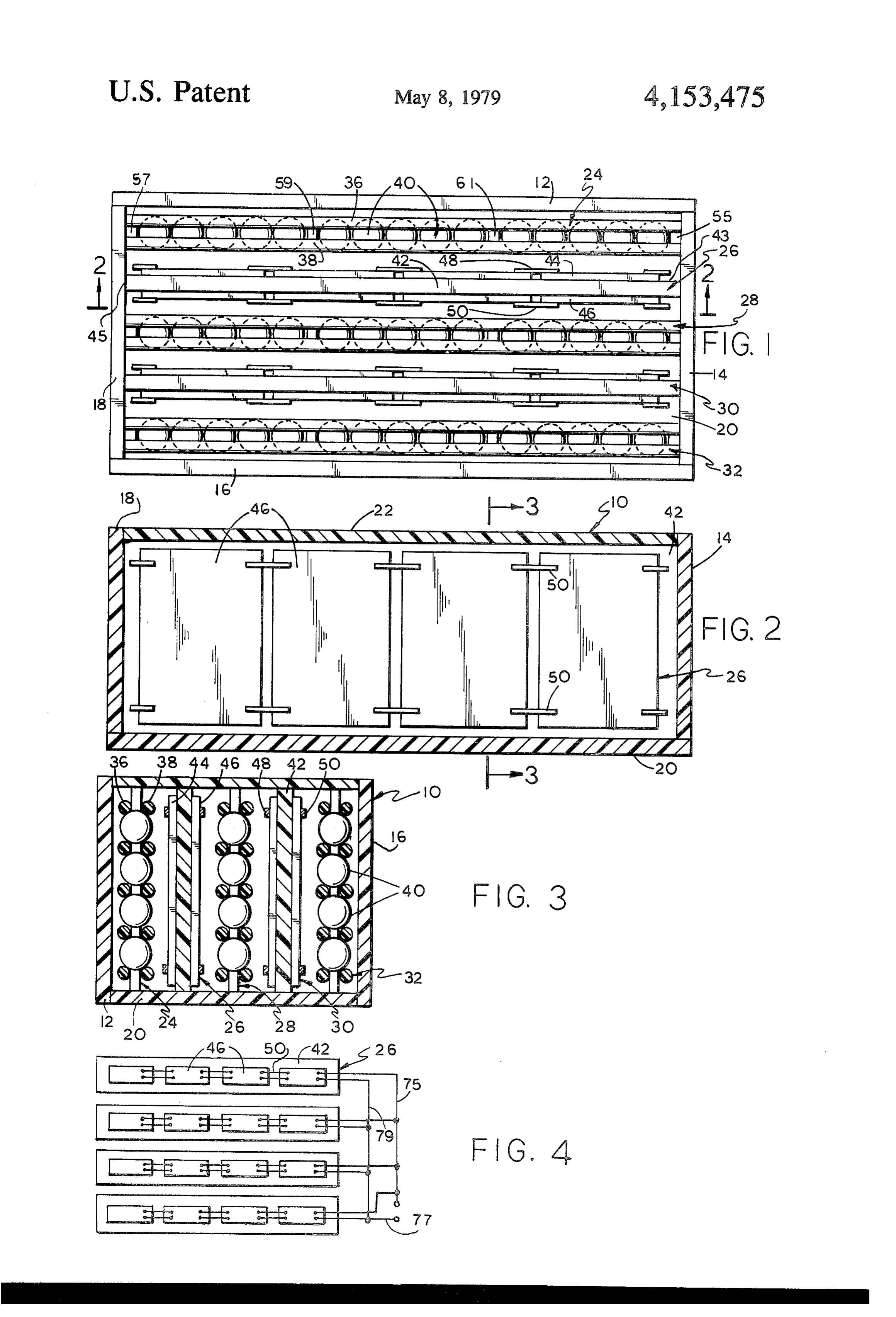
and their efficiency is low. Further, such solar cells are 15 FIG. 1 is a top plan view of an embodiment of the limited by surface area presentation to sunlight. More invention, with the top cover removed. importantly, such solar cells are limited in practical use FIG. 2 is a lengthwise section of the embodiment of because they are fragile, are easily damaged, and are not FIG. 1, taken along lines 2-2.
packaged in units that allow their practical use for on 20 FIG. 3 is a crosswise section of the embodiment of the-spot power generation. Present systems do not FIGS. 1 and 2, taken along lines 3-3 of FIG. 2. FIG. 4 is the diagram of the electrical wiring inter achieve a reasonable degree of utilization of the sunlight connecting in practical stacked arrangements. the solar cells.
It is therefore advantageous to provide a strong, three Referring now to the drawing, a rectangular box dimensional assembly of spaced solar cell panels that 25 panel shaped structure encloses the three dimensional solar facilitates their adequate access to light, and yet provide may beassembly 10. The walls of the enclosure, which a practical utilization of such solar cell panels in a pack sides 12, 14, 16 andplastic made of and are transparent, comprise 18; with a bottom member 20 and an aged power generating unit. upper cover 22. The respective solar cell panels 26 and SUMMARY OF THE INVENTION 30 are positioned in the enclosure. Each of these solar 30 cell panels comprises a panel member, as for example
In an exemplary embodiment of the three dimen panel sional solar cell panel assembly, a plurality of solar cell cells, as42,foronexample, which are mounted a plurality of solar solar cells 44 and 46. The solar panel units having substantially flat side surfaces and cells are electrically connected by electrical connectors outer rectangular edges are aligned in spaced side by 48, 50, 75, 77 and 79 (See FIG. 4). The transparent side, parallel arrangements. Light directing means are 35 structural panel 42 may comprise any suitable material, positioned between each of the solar cell panels so that such as plastic or the like, and is secured at its ends 43 light directed substantially toward the side edges of the and 45 to the end wall members 14 and 18. solar cell panels will, in addition to obliquely contacting Each of the light directing means comprises light the side surfaces of the solar panels, also direct light into receiving and directing panels 24, 28 and 32. Each of the light redirecting means that redirects the light to these panels, as for example panel 24, see FIGS. 1 and 3, contact the side surfaces of the panels. This allows the comprises rows of transparent light directing balls 40 solar panels to be packaged in stacked arrangements, that are arranged longitudinally and vertically and are and yet be presented to the light in the stacked arrange held in position by pairs of longitudinal rods 36, 38. The ment in a manner that the light passes between the solar ends of the respective rods 36, 38 are connected to cell panels and contacts the side surfaces of the solar 45 vertical end members 55 and 57 that are in turn secured cell panels so that the entire packaged solar cell panel to end plates 14 and 18. Also positioned midway the assembly generates usable power. length of the light redirecting panels are vertical mem The solar cell panels are joined at their end edges to bers 59 and 61 that maintain rigidity and integrity of the end plates that fix the correct alignment between the panels 24 along the length thereof.
solar panels and the panel shaped light directing means, 50 While each of the respective panels may be con and are held rigidly in these positions. With top and nected to the bottom member 20, normally the securing bottom covers, a box enclosure is formed. The box may of the panels at each of their ends provides sufficient be enclosed as necessary to protect the solar panels strength and connection to maintain the structural in from the elements, and yet provide a rigid structure that tegrity of the unit.
may be subjected to normal use and wear and tear, and 55 The cover 22 as well as the side members 12, 14, 16 still not allow injurious contact with the fragile side and 18 are all transparent, so that light may be received surfaces of the individual solar cells. This provides a therethrough and directed to the solar cells. Referring practical package for providing power output for im to FIG. 2, it may be understood that each of the solar mediate, on-the-spot use through multiple solar cell cell panels, as for example solar cell panel 26, has a panels, that is, packaged for practical use. plurality of solar cells 46 positioned thereon that are The light directing or redirecting panels in the exem electrically connected to provide the desired voltage plary embodiment comprise vertically and horizontally and amperage output commensurate with the particular arranged transparent balls that may be optical glass or solar cells used, through the electrical connections as may be made of plastic. The balls are held in the panel illustrated in FIG. 4.
by horizontal transparent rods that are held in position 65 In operation, the solar cell panel assembly is generally by vertical section members. The balls receive and oriented so that the light source is normal to the upper transmit the light both outwardly to the panels, and cover 22. The light then passes through the transparent vertically, thus spreading the light received from the cover 22 and contacts the surfaces of the solar cells and 4 the respective transparent members of the light receiv 2. An assembly as claimed in claim 1, wherein: ing and redirecting panels. Each of the spherical balls 40 one side edge of each of said solar cell panels forms an may be made of optical glass, or can be made of plastic. upper side edge and the opposite side edge forms a Each of the rods 36 and 38 are transparent and also may lower side edge, be made of plastic. As the light contacts these members, said solar cell panels having a substantial depth be the light passes through to the next succeeding balls, tween said upper and lower side edges; and the next succeeding rods, and on through the panel. and said light directing means comprises a plurality of Additionally, the light is redirected by the respective light directing panels having means for absorbing members and is refracted outwardly, where it contacts and redirecting light to substantially all of the side the adjacent side surfaces of the solar cells 46. Also 10 surfaces of each solar panel, which light directing since the light is a movable source, and the panel is also panels extend substantially the length of said solar movable, the cover 22 will often be at an angle to nor cell panels, whereby each of said solar cell panels mal relative to the light. Thus, the light will directly in a stacked, closely spaced arrangement receives contact the side surfaces of the respective solar cell light.
panels that are on the side to which the light is received. 15 3. An assembly as claimed in claim 2, wherein: The composite package provides a strong structural said light directing panels each have a plurality of panel that may be used in normal applications that may light transparent rods connected to spaced posts, involve some physical abuse. The structure also pro with rows of said transparent balls positioned be vides protection of the panels against the elements, and tween and held by said transparent rods; makes it possible to utilize more solar cells with a 20 said rows of balls being arranged in multi-layers, greater solar cell surface area in a limited physical area. extending the depth of the solar cell panels be Having described our invention, we now claim: tween said upper and lower side edges. 1. A three dimensional solar panel assembly, compris 4. An assembly as claimed in claim 4, wherein: 1ng: said enclosure has vertically arranged end walls; an enclosure which is at least partially transparent to 25 the opposite ends of each of said light directing panels light, said enclosure containing at least a pair of being fixed to said end walls; elongated solar cell panels in closely spaced, side and opposite ends of each of said solar cell panels by-side parallel relation; being connected to said end walls in spaced rela each of said solar cell panels having side edges and tion to maintain a rigid, box-like structure which substantially flat side surfaces between the side 30 holds said solar cell panels and said light directing edges; panels in fixed aligned positions in the side-by-side, and light directing means positioned on each side of parallel relation.
each of the solar cell panels for receiving light 5. An assembly as claimed in claim 4, wherein: directed primarily at said side edges and redirect said enclosure further includes a pair of side walls, a ing the received light to the side surfaces of the 35 bottom member and a transparent top cover, for solar cell panels; enclosing said solar cell panels and said light direct said light directing means comprising a plurality of ing panels into an enclosed three dimensional solar light transparent balls held together in a light trans panel assembly.
parent panel structure.
Page 5scan →
United states patent and trademark office
Patent no
Certificate
Of correction
NVENTOR(S) : . Ross Brian Hider (and) Ross John Hider It is certified that error appears in the above-identified patent and that said Letters Patent are hereby Corrected as shown below:
Column 4, Line 23, in Claim 4, ''An assembly as claimed in claim 4,' should read -- An assembly as claimed in claim 3, --. signed and sealed this
Twenty-eighth Day of August 1979
Seal
Attest:
Lutrelle f. parker
Attesting officer Acting Commissioner of Patents and Trademarks
Provenance
- Collection
- Patents citing this work
- Pages
- 5
- Method
- pdftotext (the PDF's own text layer) + pdftoppm 300dpi page scans
- Patent office record
- patents.google.com →
- Source
- Google Patents citing-documents table
- Assignee
- Hider Ross B
- Published
- 1979-05-08
- Transcribed from
- patentimages.storage.googleapis.com →