

patent · US4159712A
Solar energy conversion unit
3 July 1979
Text
Page 1bibliographic recordscan →
United States Patent (19)
Legg
54). SOLAR ENERGY CONVERSION UNIT
(76) Inventor. Howard W. Legg, 2229 North Park,
Grand Island, Nebr. 68801
Int. Cl’................................................. F24J 3/02 52 U.S. C. .................................................... 126/271
1,951,403 3/1934 Goddard .............................. 126/271 3,822,692 7/1974 Demarest ............................. 126/271 3,985,119 10/1976 Oakes, Jr. ....... ... 126/271 4,015,584 4/1977 Haberman ............................ 126/271 4,066,062 1/1978 Houston ............................... 126/271
Primary Examiner-Kenneth W. Sprague
Attorney, Agent, or Firm-Clarence A. O'Brien; Harvey B. Jacobson
A solar energy conversion unit having a collector form ing a focal area in which is disposed a core assembly including a governor arranged for varying the surface area of fluid carrying tubes partly forming the core assembly that is exposed to solar radiation so as to main tain a desired fluid pressure within the conversion unit. At such time as the solar radiation impinging the collec tor becomes substantially less than that necessary to maintain suitable pressure in the fluid system of the unit, an auxiliary heater provided as part of the core assem bly can be employed to supplement or replace the solar radiation.
12 Claims, 11 Drawing Figures
Drawings
Page 2drawing sheetscan →
Page 3drawing sheetscan →
Page 4drawing sheetscan →
Page 5drawing sheetscan →
Page 6scan →
the core assembly. More specifically, a preferred em
SOLAR ENERGY CONVERSION UNIT bodiment of the invention has the collector in the form
Background of the invention
of a longitudinally extending trough substantially semi circular in cross section, with the core assembly includ 1. Field of the Invention ing a plurality of substantially parallel, coextensive This invention relates generally to energy conversion tubes arranged extending longitudinally of the extent of devices, and particularly to a solar energy conversion the trough and forming a further trough having a sub unit provided with a source of auxiliary power to re stantially semi-circular cross section. The tubes and place or supplement the normal solar energy at those collector are arranged so as to be substantially concen times as such energy is unavailable, and which is self 10 trically of one another, with the tubes being disposed governing in order to transmit a substantially constant within the trough of the collector for being protected fluid pressure to a turbine or other suitable power gen thereby from winds and other efficiency reducing ele erating device associated with the unit. ments to which the unit may be exposed. 2. Description of the Prior Art The collector advantageously includes a cover com It is generally known to provide a solar energy col 15 prising a pair of cooperating doors arranged pivotally lecting device with an arcuate radiation-reflecting col mounted on edges of the collector for swinging move lector having associated therewith a core disposed sub ment toward and away from one another. stantially at the focal axis of the collector. Such a col The core assembly advantageously further includes lector assembly is disclosed in U.S. Pat. No. 2,182,222, an auxiliary heater which selectively applies heat di issued Dec. 5, 1939, to S.A. Courtis, et al., wherein the 20 rectly to the tubes of the core assembly from a position focal axis of the reflector is disposed substantially hori between the tubes and the collector surface, but prefera zontally, and the reflector is mounted for movement bly adjacent the tubes, during periods when solar radia about a horizontal axis parallel to the disposition of the tion is unavailable to the unit. radiation-receiving core. The single-passage core of this The core assembly preferably further includes a plu known solar heater must be arranged at the focal axis of 25 rality of support stations, each of which stations com the reflector, which requires a considerable spacing prises a ring assembly including an inner ring and an between the reflector surface and the core, while the outer ring concentric with one another, and the outer device suffers from the basic problem with solar devices ring being rotatably mounted on the inner ring. A col that it will not operate during cloudly weather, the umn extends from the reflective surface of the collector nighttime or any other time when solar radiation is 30 and is affixed to the inner ring of the assembly for sup unavailable. porting same, with the tubes of the core assembly being U.S. Pat. Nos.: 257,560, issued May 9, 1882, to G. W. cantilever mounted on the inner ring and the auxiliary Deitzler; 497,079, issued May 9, 1893, to M. L. Severy; heater being affixed to the outer ring for movement 2,906,257, issued Sept. 29, 1959, to C. G. Abbot; and therewith relative to the tubes. The ring assembly fur 2,994,318, issued Aug. 1, 1961, to W. C. Lee, disclose 35 ther comprises a drive arrangement disposed for rotat various constructions of solar heating devices having ing the outer ring substantially 90 degrees, with this the same basic reflector and core arrangement of U.S. drive arrangement preferably including a rack provided Pat. No. 2,182,222 discussed above. about at least one-half of the outer circumference of the U.S. Pat. No. 3,990,914, issued Nov. 9, 1976, to H. outer ring. A rotatably mounted worn gear, and the Weinstein, et al., discloses a tubular solar cell mounted like, is arranged engaging the rack and connected to a within an arcuate collector, or reflector, so as to con source of power for being rotated thereby and causing vert impinging radiation directly into electrical energy. rotation of the outer ring by engagement with the rack. U.S. Pat. No. 3,822,692, issued July 9, 1974, to J. A. The core assembly advantageously further includes a Demarest, discloses a controlled solar energized power governor associated with the tubes of the core assembly generator which employs a secondary energy source in for controlling the pressure of a working fluid provided order to obtain a controlled temperature and pressure of in the passage, or passages, formed in the tubes. This a working fluid within the system. governor includes a shield mounted for reciprocating
Summary of the invention
movement relative to the tubes of the core assembly, with this shield being disposed between the tubes and
It is an object of the present invention to provide a 50 collector for blocking radiation reflected on the collec solar energy converting unit capable of operating at a tor from striking a portion of the tubes overlapped by substantially constant fluid pressure. the shield. A servo motor responsive to a fluid pressure It is another object of the present invention to pro in the tubes is connected to the shield for positioning vide a solar energy conversion unit capable of operating same relative to the tubes as a function of the fluid continuously, irrespective of whether solar radiation is 55 pressure in the tubes.
available at a given time. The frame of the unit preferably comprises a post on It is yet another object of the present invention to which an arm is rotatably mounted and extends longitu provide a solar energy conversion unit having a fluid dinally from the post so as to terminate in a free end carrying core structure of greater efficiency than the thereof with a wheel rotatably mounted on the arm. conventional structures used as collector cores. The collector is pivotally mounted on the arm adjacent These and other objects are achieved according to the wheel, and is supported for vertical swinging move the present invention by provided a solar energy con ment relative to the post and arm by a linear motor version unit having: a collector forming a focal area; a pivotally mounted on the post and connected to the frame for mounting the collector for movement with collector.
the sun; and a core assembly forming a fluid passage and 65 These together with other objects and advantages mounted on the frame at the focal area of the collector which will become subsequently apparent reside in the for receiving solar radiation from the collector and details of construction and operation as more fully here heating a fluid passing through the passage formed by inafter described and claimed, reference being had to 7 the accompanying drawings forming a part hereof, and collector 12, and brings an auxiliary heater, to be wherein like numerals refer to like parts throughout. described below, into and out of an operating mode relative to tubes 18.
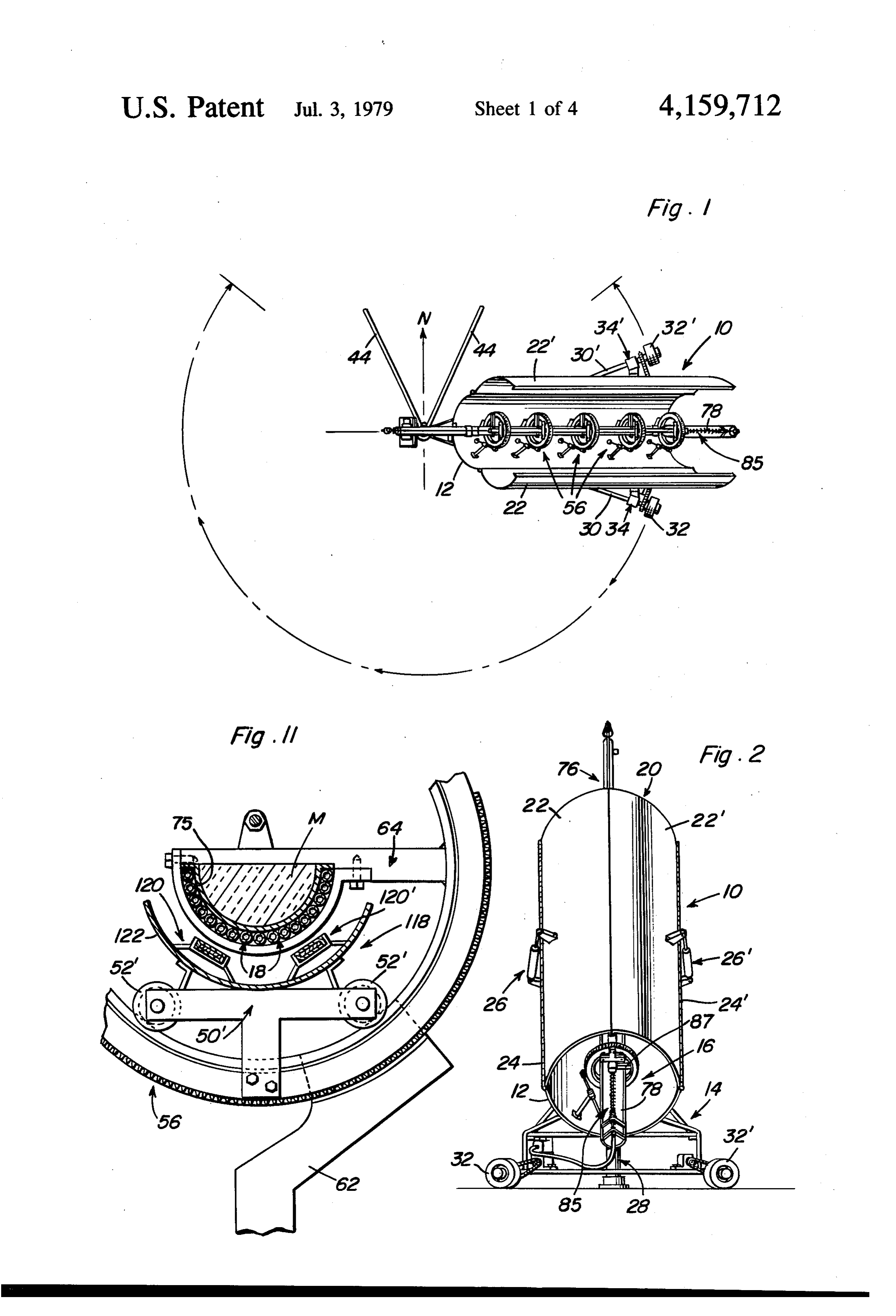
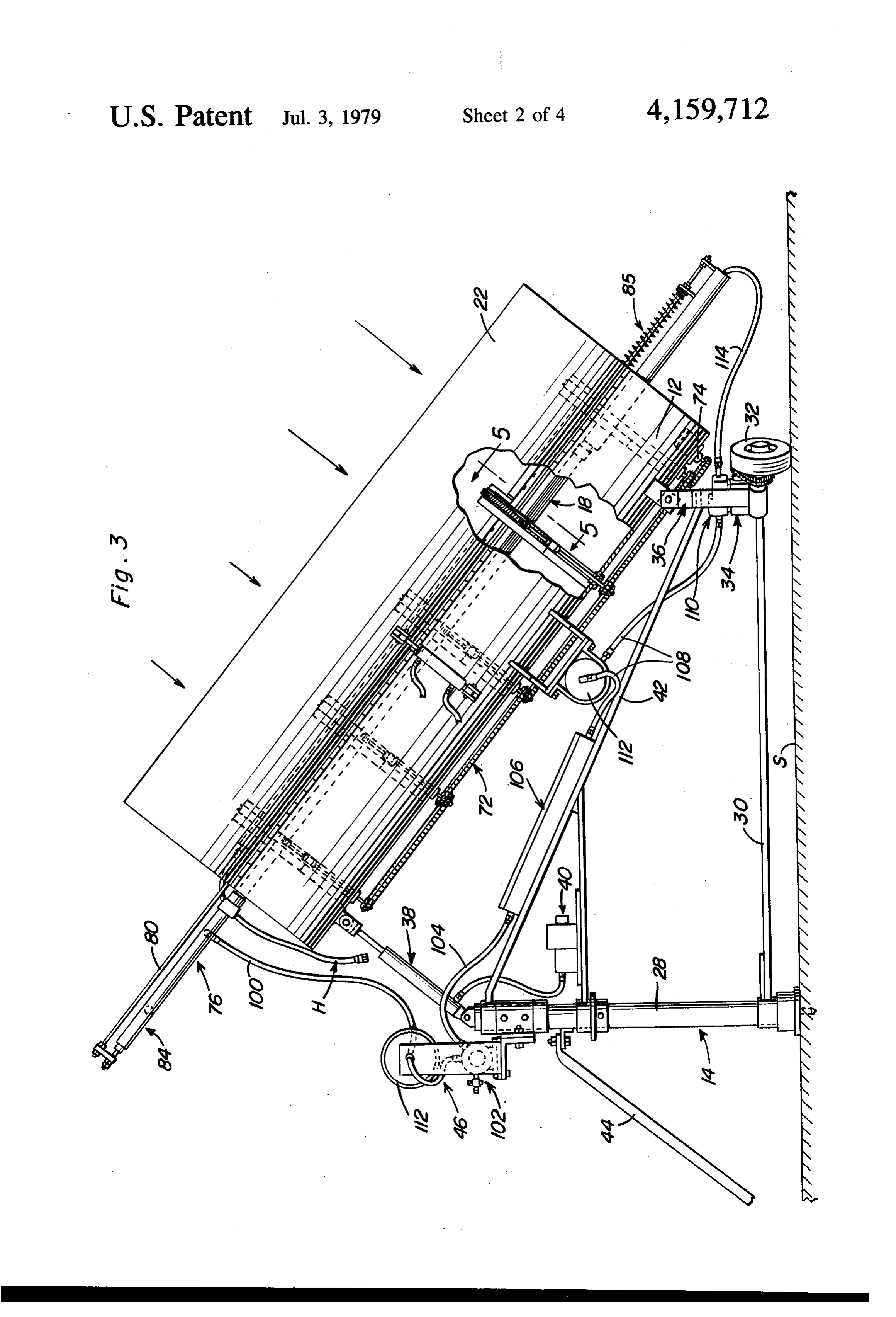
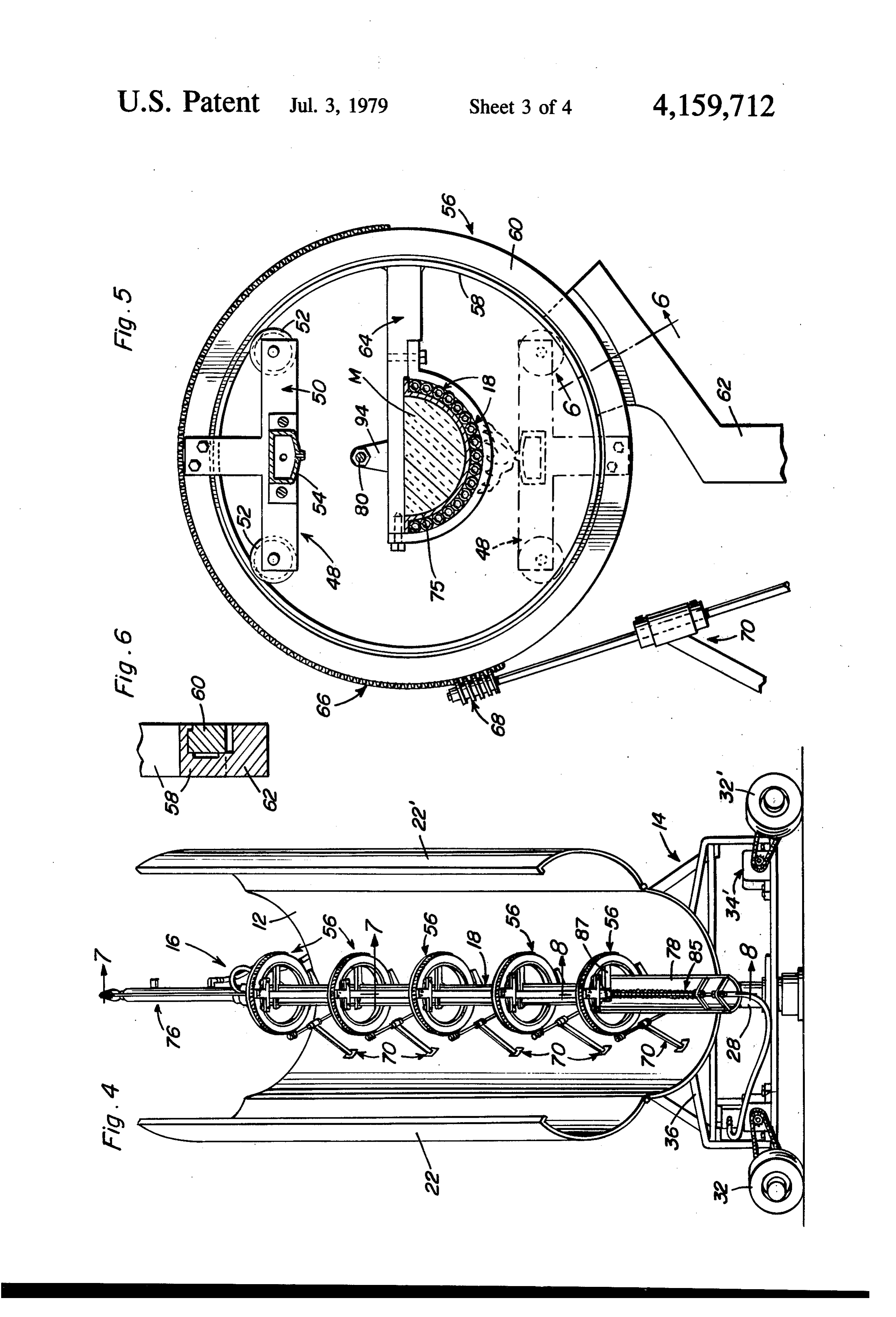
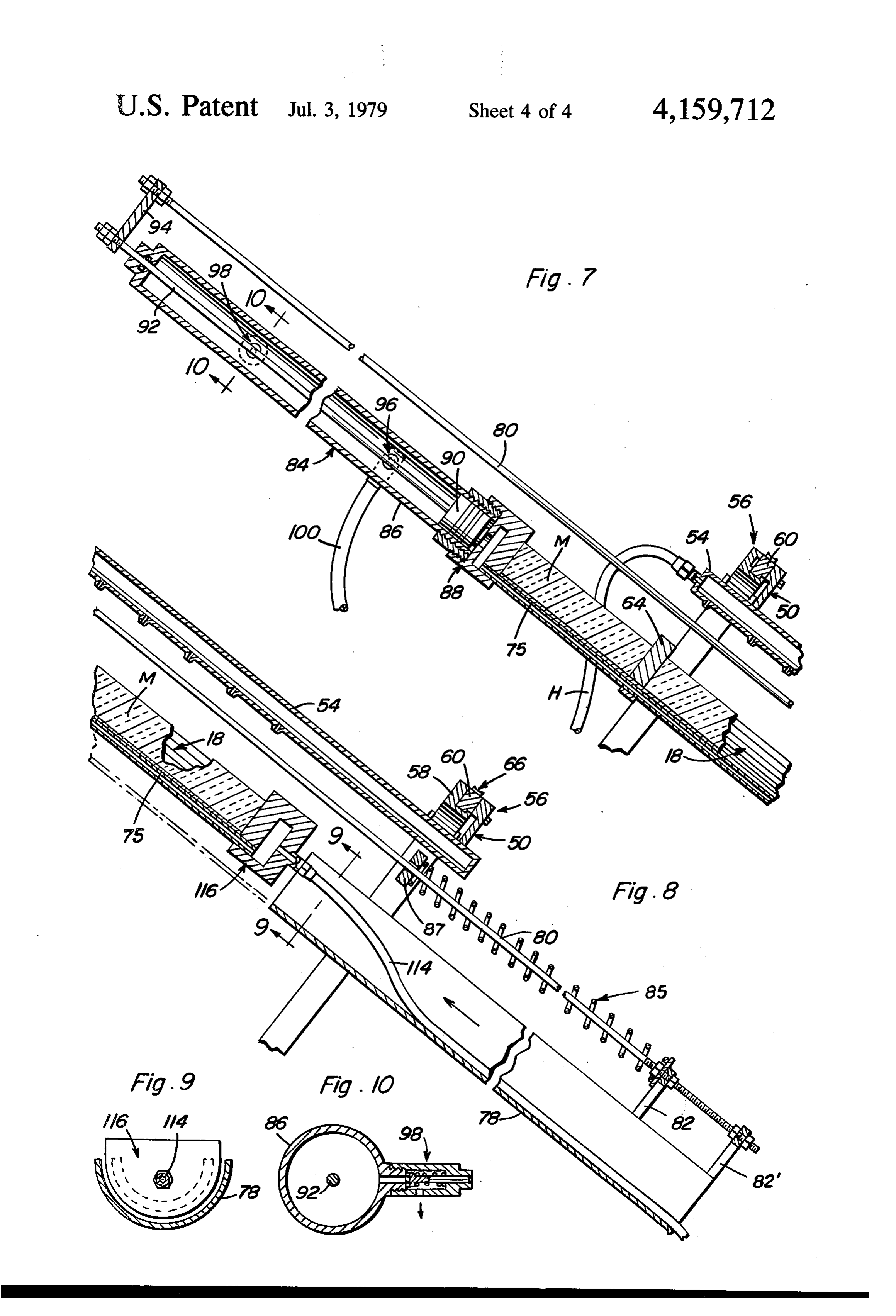
BRIEF DESCRIPTION OF THE DRAWINGS Frame 14 includes a generally vertically disposed FIG. 1 is a partly schematic, top plan view showing post 28 which advantageously has the illustrated down a solar energy conversion unit according to the present wardly projecting pin for anchoring post 28 to a surface invention. S, and the like, and which has rotatably mounted FIG. 2 is an enlarged, front elevational view of the thereon adjacent surface S, as by a suitable collar, a pair conversion unit seen in FIG. 1, but with the collector of arms 30 and 30', for example, extending longitudi cover doors seen in a closed mode. O nally from post 28 to a free end. A respective wheel32, FIG. 3 is an enlarged, fragmentary, side elevational 32' is rotatably mounted on arms 30, 30' at the free ends view, partly cut away into section, showing the conver thereof, with collector 12 being pivotally mounted on sion unit as seen in FIG. 1. the arm adjacent wheel 32, 32. Each wheel 32, 32 has FIG. 4 is an enlarged, front elevational view showing associated therewith a respective drive motor 34, 34' the conversion unit with the doors open as seen in FIG. 15 mounted on arm 30, 30' and connected directly to wheel 1. 32, 32 for selectively rotating same in cooperation with FIG. 5 is an enlarged, fragmentary, sectional view one another in order to cause frame 14 and therefore, taken generally along the line 5-5 of FIG. 3. collector 12 to rotate about an arc of some 270 degrees FIG. 6 is a fragmentary, sectional view taken gener as shown in FIG. 1. It will be appreciated that since ally along the line 6-6 of FIG. 5. 20 collector 12 need never be positioned so as to face a FIG. 7 is an enlarged, fragmentary, sectional view generally northerly direction, a full 360 degree rotation taken generally along the line 7-7 of FIG. 4. of frame 14 is unnecessary. The lower end of collector FIG. 8 is an enlarged, fragmentary, sectional view 12 can be pivotally mounted on the arms 30, 30' adja taken generally along the line 8-8 of FIG. 4. cent the free ends thereofas by the illustrated bracket 36 FIG. 9 is a sectional view taken generally along the 25 partially forming frame 14, lug portions of which line 9-9 of FIG. 8. bracket 36 are pinned to ears projecting from the lower FIG. 10 is a sectional view taken generally along the arcuate surface of collector 12.
line 10-10 of FIG. 7. A linear fluid motor 38 of conventional construction FIG. 11 is a fragmentary, cross-sectional view, simi is pivotally mounted on the upper end of post 28 and is lar to FIG. 5, but showing a modified embodiment of an 30 connected to the upwardly disposed portion of collec auxiliary heater according to the present invention. tor 12, again by a pivotal connection, for swinging col DESCRIPTION OF THE PREFERRED lector 12 vertically about the pivotal connection of collector 12 to bracket 36. Motor 38 receives fluid
EMBODIMENTS under pressure from a conventional pump unit 40 which Referring now more particularly to FIGS. 1 through 35 would be connected to a conventional source of electric 6 of the drawings, a solar energy conversion unit 10 power (not shown), and the like, by means of a suitable according to the present invention includes a collector solar tracking control system, not shown, but of a con 12 in the form of a longitudinally extending trough struction familiar to those in the solar energy tracking substantially semi-circular in cross section and creating art and of a kind generally available on the market. a focal area into which radiation impinging on the inner, A brace 42 partially forms frame 14 together with a or reflective, surface of collector 12 is directed. Collec pair of braces 44 extending from the upper portion of tor 12 is mounted on a frame 14 for movement with the post 28 so as to engage with surface S and rigidify frame sun (not shown), while a core assembly 16 forming a 14, these braces 44 being disposed relative to surface S fluid passage is disposed in the focal area of collector 12 so as to be in a generally northerly direction from post for receiving solar radiation from collector 12 and heat 45 28 and be in that sector of a circle having an axis formed ing a fluid passing through the passage formed by the by post 28 that will not be traversed by frame 14 during core assembly 16. an operating cycle of unit 10. Also mounted on frame 14 Core assembly 16 includes a plurality of substantially is a fluid system 46 which will be described in detail parallel, coextensive tubes 18 arranged extending longi below.
tudinally of the extent of the trough formed by collector 50 Core assembly 16 further includes an auxiliary heater 12, and forming a further trough having a semi-circular 48 which selectively applies heat directly to the lower cross section. The tubes 18 and collector 12 are ar surface of tubes 18 of core assembly 16 from a position ranged substantially concentrically of one another such between tubes 18 and collector 12 during periods when that the tubes 18 are protected by collector 12 from solar radiation is unavailable, such as at night or when wind and other environmental disturbances that would 55 the sky is overcast. This heater 48 includes a T-shaped tend to reduce efficiency of the unit 10 and/or damage frame 50 having a leg thereof affixed to a movable ring S3. of a ring assembly to be described below, and having Collector 12 has a pair of substantially parallel, rollers 52 provided on the crossbar thereof for facilitat spaced, longitudinally extending, peripheral edges, and ing movement relative to a fixed ring of the ring assem includes a cover 20 comprising a pair of cooperating bly. More specifically, heater 48 includes a plurality of doors 22 and 22' arranged pivotally mounted on the the frames 50 each provided with a set of rollers 52 and edges of collector 12 for swinging movement toward supporting a duct 54 extending longitudinally of the and away from one another. More specifically, doors 22 extent of collector 12, and tubes 18, and provided with and 22' are mounted as by the longitudinally extending a plurality of apertures forming burners for a combusti hinges 24, 24, respectively, and can be opened and 65 ble gas, and the like, fed into duct 54 as by hose H. closed in a known manner as by the use of the illustrated Tubes 18 and auxiliary heater 48 are supported by a jacks 26 and 26 controlled in conjunction with a con plurality of support stations, each of which stations ventional sun sensing system which positions frame 14, comprises a ring assembly 56 including an inner ring 58 8 and an outer ring 60 concentric with one another. Outer greater portion of the adjacent ends of the tubes 18, ring 60 is rotatably mounted on inner ring 58, the latter with spring 85 providing a return bias when the pres of which is fixedly supported within the trough of col sure on piston 90 is reduced. Once piston 90 moves lector 12 as by an associated one of a plurality of cols. along cylinder 86 so as to expose a valve 96 to the pres umns 62. Tubes 18 are supported within ring assembly sure of fluid in manifold 88 and tubes 18, the working 56 by a respective cantilever 64 mounted on the fixed fluid at a pressure of, for example, approximately 700 inner ring 58, while the leg of each of the T-shaped p.s. i. (48.2X10⁶ dynes per square centimeter) is allowed frames 50 of auxiliary heater 48 is affixed to outer ring to be directed into fluid system 46. A safety valve 98 is 60 for rotation therewith so as to move from the stor provided further along cylinder 86 to permit blowoff age, inoperative position seen in full lines in FIG. 5, to O from cylinder 86 should piston 90 be exposed to such a the operative position shown in broken lines in the same pressure as to move completely to the upper end of the figure. cylinder 86. Such a pressure, could be, for example, Ring assembly 56 includes a drive arrangement for 1050 p.s. i. (72.4x 10⁶ dynes per square centimeter) in rotating the outer ring 60 substantially 180 degrees, order to prevent damage to servomotor 84 or main which drive arrangement includes a rack provided 15 power turbine overrun, or it could very easily blow up. about at least one-half of the outer circumference of A fluid line 100 is connected to valve 96 and partially outer ring 60 and preferably slightly more than 180 forms degrees as illustrated, which cooperates with a rotat 96, andfluid system 46 in order to carry fluid from valve manifold 88, to a conventional turbine 102 (FIG.
ably mounted worm gear 68 arranged engaging rack 66 3) included in system 46. A line 104 connects turbine and the shaft of which is connected to a drive train 72 20 102 to a conventional condenser 106 mounted on brace and, by means of which drive train 72, to a suitable 42 of frame 14, and a further line 108 carries the con motor 74 mounted on the lower portion of the bottom surface of collector 12 and energized in a suitable man densed working fluid, which had been changed into a vapor within the tubes 18, to a conventional high pres ner, such as electric current, from the aforementioned sure pump 110. Holding tanks 112 and 112' are prefera conventional control system (not shown) which con 25 bly associated with turbine 102, by insertion into line trols the operation of pump 40.
While a chain and sprocket drive train 72 is illustrated assureandanpump 100, 110, by insertion into line 108, in order to in the drawings, it is to be understood that any suitable 102 and pump 110, of even flow the working fluid into the turbine system, such as belts and pulleys, may be employed as condensed working respectively. A line 114 carries the the drive train, with it also being understood that any 30 to a manifold 116 forming a header at thefrom fluid under pressure pump 110 lower end of suitable source of power can be employed for actuating pump 40 and motor 74. tubes 18 so that the condensed fluid can again be vapor A piece of sheet metal 75, and the like, can be formed ized within the tubes 18 and the above cycle repeated. as a trough to fit between the core supports or ring tionFIG. 11 shows a modified embodiment of the inven wherein an auxiliary heater 118 is provided in place assemblies 56 and filled with a suitable foamed material 35
M having good thermal insulating properties to form a of heater 48. This heater 118 includes a, for example, radiation and convection retard. pair of electrical heating elements 120 and 120' mounted Referring now more particularly to FIGS. 7through on an arcuate reflector 122 itself affixed to the crossbar 10 of the drawings in addition to FIGS. 1 through 6, of a T-shaped frame 50 provided with rollers 52 and core assembly 16 further includes a governor 76 associ affixed to the rotatable outer ring of a ring assembly 56 ated with tubes 18 for controlling the pressure of a for 48.
operation in essentially the same manner as heater working fluid provided in tubes 18. More specifically, governor 76 includes a generally arcuate shield 78 As can be readily understood from the above descrip mounted for reciprocating movement relative to the tion and from the drawings, a solar energy conversion longitudinal extent of tubes 18, with the shield 78 being 45 unit according to the present invention provides a com disposed between tubes 18 and the reflective surface of prehensive system for continuous power output, as at reflector 12, but adjacent to tubes 18, for blocking radia the output shaft of the turbine 102, regardless of tion reflected from the collector 12 to the portion of whether solar energy is available. Collector 12 and tubes 18 overlapped by shield 78. This shield 78 is sus frame 14 on which the collector is mounted can be pended from a rod 80 as by the illustrated hangers 82, 50 caused to track the sun in a conventional manner by use 82 for connection by means of rod 80 to a servo motor of known sun sensing systems, or the jacks 26, 26 and 84 responsive to a fluid pressure within the passages the motors 34, 34, 38, and 74 can be manually operated formed by tubes 18 so as to position shield 78 relative to as by the use of conventional switches (not shown). tubes 18 as a function of such fluid pressure, while a While only a single unit is disclosed, it is to be under coiled compression spring 85 is arranged surrounding 55 stood that the units can be mounted in plural form by rod 80 between hanger 82 and a bracket 87 mounted on suitable side-by-side arrangement in a manner not the lowermost ring 58 for biasing shield 78 away from shown.
tubes 18. The foregoing is considered as illustrative only of the Servomotor 84 includes a cylinder 86 connected at a principles of the invention. Further, since numerous one end directly to a manifold 88 forming a header for modifications and changes will readily occur to those the upper end of tubes 18, and slidably receiving a pis skilled in the art, it is not desired to limit the invention ton 90, the piston rod 92 of which passes through the to the exact construction and operation shown and upper end wall of cylinder 86 and is connected to the described, and accordingly all suitable modifications adjacent end of rod 80 as by the illustrated coupling 84. and equivalents may be resorted to, falling within the By this arrangement, it will be appreciated that move 65 scope of the invention.
ment of piston 90 away from manifold 88 will cause What is claimed as new is as follows: piston rod 92 to move rod 80 and, therefore, shield 78 in 1. A solar energy conversion unit, comprising, in the same direction so that shield 78 will overlap a combination:
Page 9scan →
(a) a collector forming a focal area for radiation re connected to a source of power for rotation thereby and ceived from the sun; rotating the outer ring relative to the inner ring. (b) frame means for mounting the collector for move 4. A structure as defined in claim 3, wherein the core ment with the sun; means further includes an auxiliary heater means for (c) core means forming a fluid passage and mounted selectively applying heat directly to the tubes of the on the frame and arranged at the focal area of the core means from a position between the tubes and the collector for receiving solar radiation from the collector during periods when solar radiation is unavail collector and heating a fluid passing through the able.
passage formed by the core means, wherein the 5. A structure as defined in claim 4, wherein the col collector is a longitudinally extending trough sub O lector has a pair of substantially parallel, spaced, longi stantially semicircular in cross section, with the tudinally extending, peripheral edges, and includes a core means including a plurality of tubes arranged cover comprising a pair of cooperating doors arranged extending longitudinally of the extent of the trough pivotally mounted on the edges of the collector for and forming a further trough having a semicircular Swinging movement toward and away from one an cross section, the tubes and collector being ar 15 other.
ranged substantially concentrically with one an 6. A structure as defined in claim 5, wherein the core other with the tubes being disposed within the means further includes governor means associated with trough, wherein the collector has a pair of substan the tubes for controlling the pressure of a working fluid tially parallel, spaced, longitudinally extending, provided in the tubes.
peripheral edges, and includes a cover comprising 20 7. A structure as defined in claim 6, wherein the gov a pair of cooperating doors arranged pivotally ernor means comprises, in combination: mounted on the edges of the collector by longitudi (3) a shield mounted for reciprocating movement nally extending hinges for swinging movement relative to the tube of the core means, the shield toward and away from one another. being disposed between the tubes and collector for 2. A solar energy conversion unit, comprising, in 25 blocking radiation reflected on the collector from a combination:
(a) a collector forming a focal area for radiation re portion of the tubes overlapped by the shield; and ceived from the sun; (4) servo means connected to the shield and to the (b) frame means for mounting the collector for move tubes, and responsive to a fluid pressure in the ment with the sun; 30 tubes, for positioning the shield relative to the tubes (c) core means forming a fluid passage and mounted as a function of fluid pressure in the tubes. 8. A structure as defined in claim 7 wherein the frame on the frame and arranged at the focal area of the means includes, collector for receiving solar radiation from the in combination: collector and heating a fluid passing through the (5) a post;
passage formed by the core means, wherein the 35 (6)ing an arm rotatably mounted on the post and extend longitudinally from the post to a free end;
collector is a longitudinally extending trough sub stantially semicircular in cross section, with the (7) a wheel rotatably mounted on the free end of the core means including a plurality of tubes arranged arm, the collector being pivotally mounted on the extending longitudinally of the extent of the trough arm adjacent the wheel; and and forming a further trough having a semicircular (8) linear motor means pivotally mounted on the post cross section, the tubes and collector being ar and connected to the collector for swinging the ranged substantially concentrically with one an collector vertically above the pivotal mounting of other with the tubes being disposed within the the collector on the arm.
9. A solar energy conversion unit, comprising, in trough, the core means further including an auxil combination:
iary heater means for selectively applying heat 45 directly to the tubes of the core means from a posi (a) a collector forming a focal area for radiation re tion between the tubes and the collector during ceived from the sun;
periods when solar radiation is unavailable, and the (b) frame means for mounting the collector for move core means further including a plurality of support ment with the sun;
stations, each of which support stations comprises, 50 (c) core means forming a fluid passage and mounted in combination: on the frame and arranged at the focal area of the (1) a ring assembly including an inner ring and collector for receiving solar radiation from the outer ring concentric with one another, the outer collector and heating a fluid passing through the ring being rotatably mounted on the inner ring; passage formed by the core means, wherein the and 55 core means includes a plurality of longitudinally (2) a column extending from the collector and extending tubes and the core means further in affixed to the inner ring for supporting the ring cludes an arcuate shield for controlling the pres assembly, the tubes being cantilever mounted on sure of a working fluid in the passage provided in the inner ring and the auxiliary heater means the core means, responsive to the pressure of the being affixed to the outer ring for movement fluid in the passage so as to position the shield therewith relative to the tubes. relative to the tubes as a function of such fluid 3. A structure as defined in claim 2, wherein the outer pressure.
ring has an outer circumference, and the ring assembly 10. A solar energy conversion unit, comprising, in further comprising drive means for rotating the outer combination:
ring substantially 180 degrees, the drive means includ 65 (a) a collector forming a focal area for radiation re ing a rack provided about at least one-half of the outer ceived from the sun;
circumference of the outer ring, and a rotatably (b) frame means for mounting the collector for move mounted worm gear arranged engaging the rack and ment with the sun;
Page 10scan →
(c) core means forming a fluid passage and mounted on the frame and arranged at the focal area of the collector for receiving solar radiation from the collector and heating a fluid passing through the passage formed by the core means, wherein the 5 frame means includes, in combination:
(2) an arm rotatably mounted on the post and ex tending longitudinally from the post to a free (3) a wheel rotatably mounted on the free end of the arm, the collector being mounted on the arm adjacent the wheel; and (4) linear motor means pivotally mounted on the post and connected to the collector for swinging 15 the collector vertically above the pivotal mount ing of the collector on the arm.
11. In a solar energy conversion unit comprising a collector and a core assembly having a passage forming core holding a working fluid, a governor for controlling 20 the pressure of the working fluid, the governor com prising, in combination:
(a) a shield mounted for reciprocating movement relative to the passage forming core of the unit, the shield being disposed between the core and the 25 collector of the unit for blocking radiation re flected from the collector toward a portion of the core being overlapped by the shield; and (b) servo means connected to the shield and connect able to the core of the unit and responsive to the 30 pressure of the working fluid in the core for posi tioning the shield relative to the core as a function of fluid pressure in the core.
12. A collector assembly for a solar energy conver on unit, comprising, in combination:
(a) a collector having a reflective surface forming a focal area; and (b) core means including a plurality of longitudinally extending, co-extensive, tubes forming a multi-sec tion fluid passage and arranged at the focal area of the collector for receiving solar radiation from the collector and heating a fluid passing through the passage formed by the tubes, the core means fur ther including an auxiliary heater means associated with the tubes for selectively applying heat directly to the tubes of the core means from a position be tween the tubes and collector during periods when solar radiation is unavailable, the core means fur ther including a plurality of support stations, each of which support stations comprises, in combina tion:
(1) a ring assembly including an inner ring and outer ring concentric with one another, the outer ring being rotatably mounted on the inner ring; and (2) a column extending from the collector and affixed to the inner ring for supporting the ring assembly, the tubes being cantilever mounted on the inner ring and the auxiliary heater means being affixed to the outer ring for movement therewith relative to the tubes.
Provenance
- Collection
- Patents citing this work
- Pages
- 10
- Method
- pdftotext (the PDF's own text layer) + pdftoppm 300dpi page scans
- Patent office record
- patents.google.com →
- Source
- Google Patents citing-documents table
- Assignee
- Legg Howard W
- Published
- 1979-07-03
- Transcribed from
- patentimages.storage.googleapis.com →