

patent · US4175523A
Internal combustion engine and a method for operation thereof
27 November 1979
Text
Page 1bibliographic recordscan →
United States Patent (19)
Noguchi et al.
54 INTERNAL COMBUSTION ENGINE ANDA
METHOD FOR OPERATION THEREOF
Inventors: Masaaki Noguchi, Nagoya;
Masaharu Sumiyoshi, Toyota;
Tsuchio Bunda, Okazaki; Taro
Tanaka, Chiryu, all of Japan 73 Assignee: Nippon Soken, Inc., Nishio, Japan
30 Foreign Application Priority Data
Mar. 29, 1977 JP Japan .................................. 52-35008
52 U.S. C. ..................................... 123/119 A; 123/3 58 Field of Search ................................ 123/3, 119 A
l,625,007 4/1927 Weeber ............................ 123/119A 3,855,890 12/1974 Weisz et al. ............................. 123/3 3,908,606 9/1975 Toyoda et al. .......................... 123/3 3,980,052 9/1976 Noguchi et al.......................... 123/3 4,059,076 l/1977 Kosaka ..................................... 1.23/3
4,074,661 2/1978 Noguchi et al. ......................... 123/3 Primary Examiner-Wendell E. Burns
Attorney, Agent, or Firm-Cushman, Darby & Cushman
An internal combustion engine is provided with an EGR system and a system for catalytic coversion of a rich air-fuel mixture into a reformed combustible gase ous mixture rich with free hydrogen. During a low or medium engine load engine operation, the engine is operated solely by an air-gasoline mixture and with an exhaust gas recirculation at a rate not higher than a predetermined first EGR rate. During a high engine load engine operation, the reformed combustible gase ous mixture is added to the air-gasoline mixture supply and simultaneously the exhaust gas recirculation is in creased to a rate higher than the predetermined first EGR rate to increase the engine output, improve the engine drivability and improve the consumption of the reformed combustible gaseous mixture. The intake man ifold vacuum is electrically detected to determine the load on the engine and to control valves associated with the EGR system and reformed gas supply system.
18 Claims, 2 Drawing Figures
WACUUM
RESPONSIVE
EECRC
SWITCH
Drawings
Page 2drawing sheetscan →
Page 3drawing sheetscan →
Page 4scan →
engine load exceeds the predetermined load level, the
INTERNAL COMBUSTON ENGINE AND A reformed combustible gaseous mixture is added to the WEETHOD FOR OPERATION THEREOF air-gasoline mixture supply and substantially simulta neously the exhaust gas recirculation is increased to a
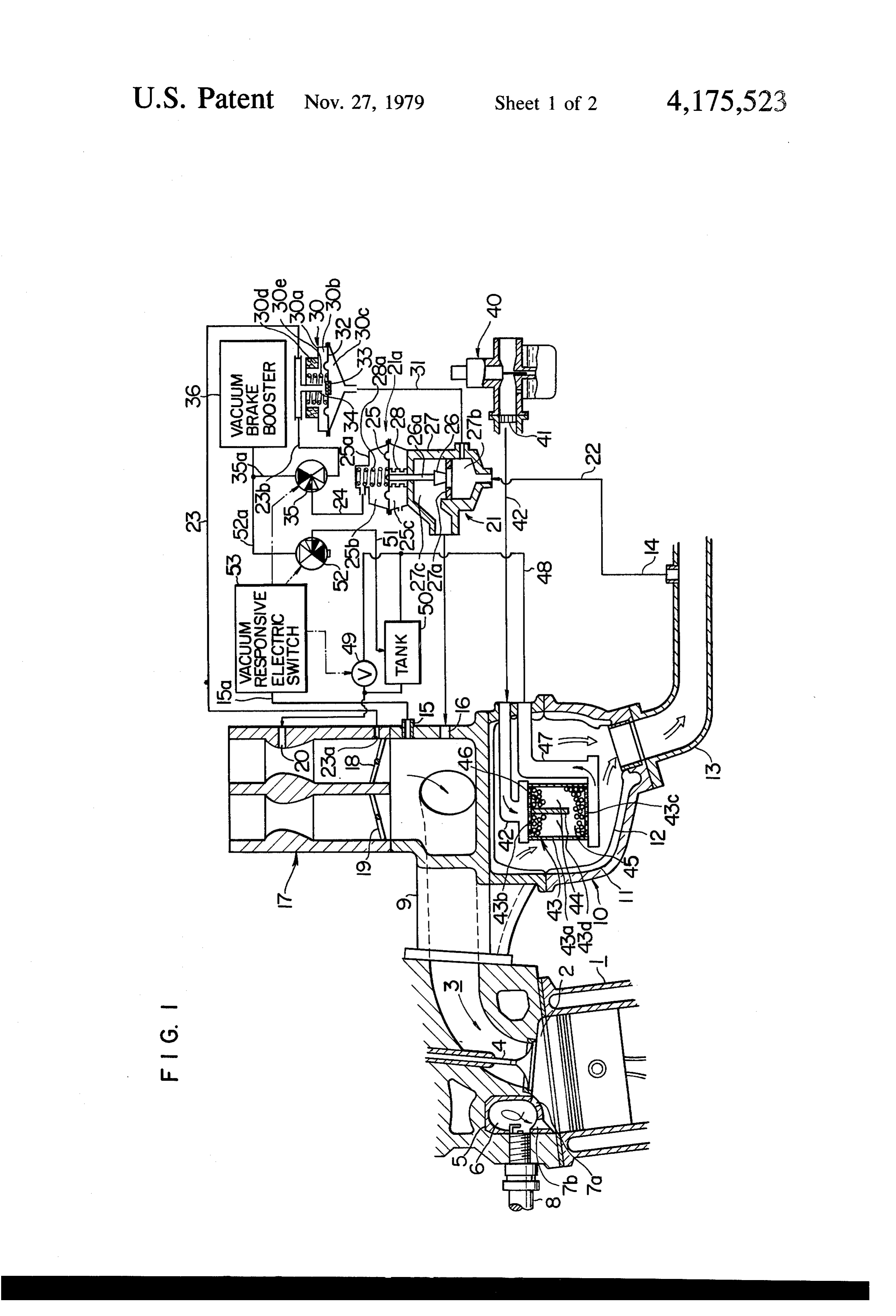
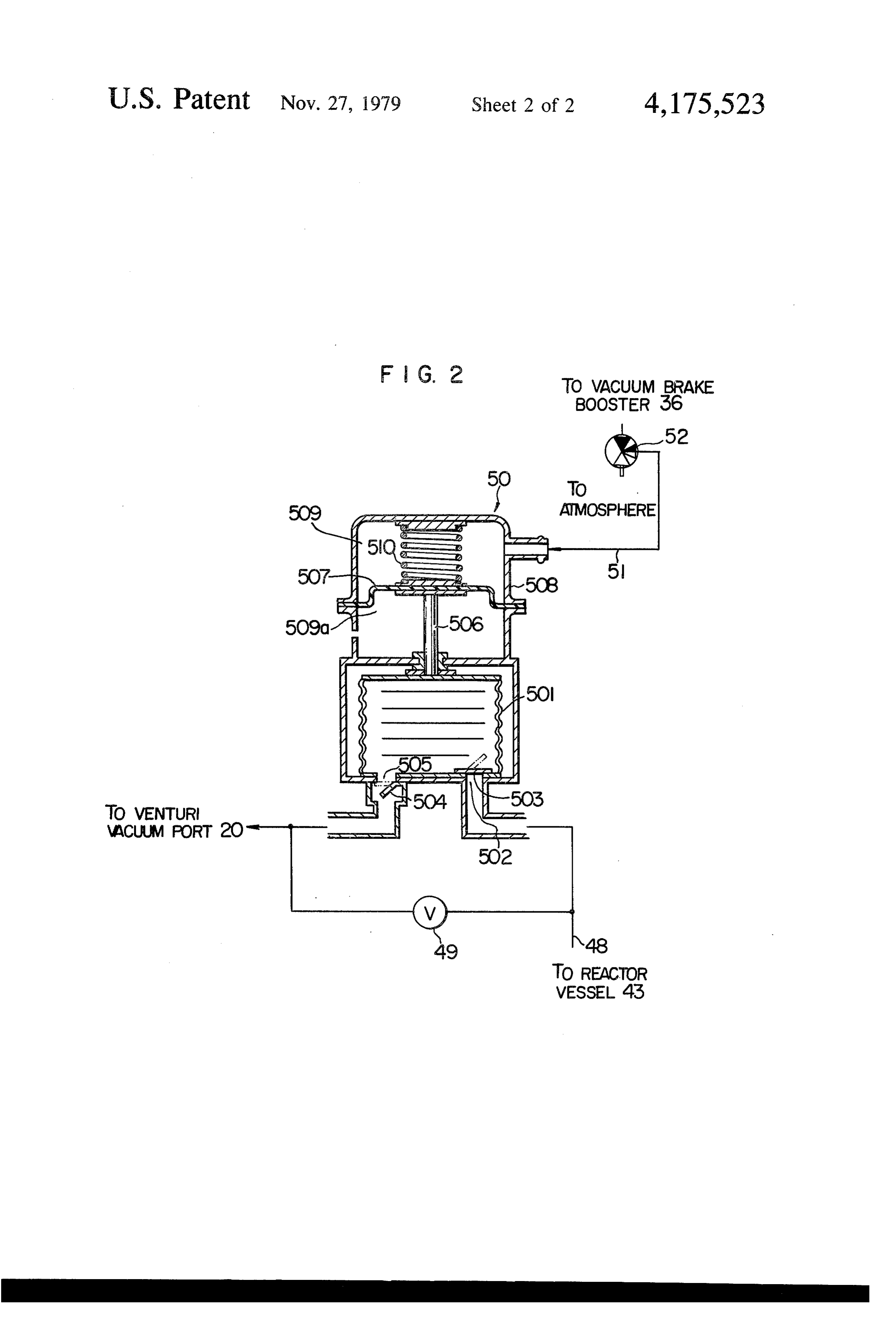
RELATED APPLICATION rate higher than the predetermined first EGR rate. This application is generally related to the applicants' It is another object of the present invention to pro earlier copending application Ser. No. 641,603, now vide an internal combustion engine with an EGR sys abandoned filed Dec. 17, 1975. The disclosure in the tem, a fuel reforming system for converting a rich mix earlier application is incorporated herein by reference. O ture of air and a fuel into a reformed combstible gaseous BACKGROUND OF THE INVENTION mixture rich with free hydrogen and feeding the re formed mixture into an intake system of the engine, and . . Field of the Invention means responsive to variation in the load on the engine The present invention relates to an internal combus to control the exhaust gas recirculation and the supply tion engine and a method of operation thereof and, 5 of the reformed combustible gaseous mixture from the more particularly, to an internal combustion engine fuel reforning system into the intake system so that the equipped with a fuel reforning system and an exhaust exhaust gas recirculation and the reformed gas supply gas recirculation system (EGR system) and a method are controlled in the manner specified above. for the operation of the engine of the type specified. Preferably, the intake manifold vacuum may be elec 2. Description of the Prior Art trically detected to determine the load on the engine to Internai combustion engines equipped with fuel re electrically actuate valves associated with the EGR forming systems have heretofore been proposed to si system and the reformed gas supply system. multaneously reduce kinds of harmful components of The above and other objects, features and advantages engine exhaust gases and to improve the engine driva of the present invention will be made apparent by the bility.
25 following
The internal combustion engine of this type has been ing drawings. description with reference to the accompany operated by the supply of combustible gases at a lean air-fuel ratio such as from 18 to 22, for example. The BRIEF DESCRIPTION OF THE DRAWINGS combustible gases consisted of a mixture of air and FIG. 1 is a partly sectional and partly diagrammatic gasoline and a reformed gaseous mixture produced by the reformation of a hydrocarbon fuel, such as gasoline, 30 illustration of an embodiment of an internal combustion or an alcohol, such as methanol or ethanol. The engine engine according to the present invention; and was operated in such a manner that the reformed gase FIG. 2 is an enlarged sectional view of a tank for ous mixture was always supplied into the engine regard accumulating a reformed combustible gaseous mixture. less of the engine operating conditions. In the case DESCRIPTION OF A PREFERRED where a hydrocarbon fuel was used to produce a re 35 EMBOOMENT formed gaseous mixture, an energy loss occurred in the fuel reforming process. This manner of engine opera Referring first to FIG. , a spark-ignition type, 4 tion, therefore, has not much contributed to the in stroke, reciprocal piston internal combustion engine 1 is provement in the total fuel consumption rate. shown as having a main combustion chamber 2 defined 40 by a piston, a cylinder and a cylinder head. The main
The use of an alcohol to produce a reformed combus combustion chamber 2 is connected with an intake port tible gaseous mixture is advantageous in that alcohol is 3 formed in the cylinder head. An intake valve 4 is easy to reform and energy loss hardly occurs. However, mounted on the cylinder head and reciprocally movable difficulties have been found in the use of alcohols that in timed relationship with the engine crankshaft rota gaseous combustible mixtures obtained by the reforma 45 tion. The intake valve 4 has a valve head which is recip tion of alcohols are more expensive than other kinds of rocally moved relative to a valve seat to control the reformed gaseous mixtures and the calorie per unit communication between the main combustion chamber volume of an alcohol is lower than that of gasoline with 2 and the intake port 3 in known manner. a resultant increase in the fuel consumption. The cylinder head is formed with a hole directed to
SUMMARY OF THE INVENTION the main combustion chamber 2. A trap chamber insert It is an object of the present invention to provide an Sinneris fitted into the hole and defines a trap chamber 6 the surface of which is smoothly curved and com improved engine operation method which minimizes prises an internediate cylindrical surface and opposite the consumption of a reformed combustible gaseous concave mixture to improve the fuel consumption of an engine, 55 tinuouslyhemispherical end surfaces smoothly and con reduces the emission of harmful engine exhaust gas surface, respectively. the intermediate cylindrical connected to components and improves engine drivability.
According to the method of the present invention, an Two torch apertures 7a and 7b are formed in the trap internal combustion engine provided with an EGR chamber insert 5 in one of the ends thereof adjacent to system and a fuel reforming system for converting a 60 the main combustion chamber 2 to intercommunicate rich mixture of air and a fuel into a reformed combusti the trap chamber 6 and the main combustion chamber 2. ble gaseous mixture rich with free hydrogen is operated The ends of the torch apertures 7a and 7b adjacent to such that, when the load on the engine is lower than a the trap chamber 6 are open thereto substantially tan predetermined load level, the combustion chamber of gentially to the inner surface of the chamber 6. The the engine is supplied with a mixture of air and gasoline 65 other end of the torch aperture 7a is open to the main and the engine exhaust gases are recirculated back into chamber 2 and directed generally toward the valve the combustion chamber at a rate not higher than a head of the intake valve 4 when the valve head is in its predetermined first EGR rate and such that, when the open position. The other end of the other torch aperture
Page 5scan →
7b is open to the main chamber 2 and directed substan three-way solenoid valve 35 which in turn is pneumati tially to the piston. cally connected by a line 24 to the vacuum chamber 25b A spark plug 8 is mounted on the cylinder head so in the diaphragm housing 25a of the EGR valve actua that a set of electrodes extend into the trap chamber 6 tor 21a.
and disposed adjacent to the torch aperture 7b. The throttle vacuum modulating valve 30 is opera The intake port 3 is connected with an intake mani tive in response to variation in the engine exhaust gas fold 9. An exhaust port (not shown) is also formed in the pressure to modulate the throttle vacuum to be exerted cylinder head and connected with an exhaust manifold to the diaphragm 25 of the EGR valve actuator 21a. 10. The intake and exhaust manifolds 9 and 10 are con For this purpose, the throttle vacuum modulating valve nected together at their bottom and top. The exhaust 10 30 comprises a housing 30a, a diaphragm 32 disposed manifold 10 is of a double-walled structure which com therein and cooperating therewith to define an atmo prises an outer shell 11 of a cast metal and an inner shell spheric chamber 30b and an exhaust gas chamber 30c 12 disposed in the outer shell 11. The double-walled which is always communicated by a line 31 with the structure is effective to keep hot the interior of the chamber 27b in the EGR valve housing 27. The atmo exhaust manifold 10. The exhaust manifold 10 consists 15 spheric chamber 30b is communicated with the atmo of upper and lower sections which can be separated sphere through an annular filter 30d extending around a apart. part of the chamber 30b. A compression coil spring 30e The exhaust manifold 10 has an exhaust gas outlet to is disposed in the atmospheric chamber 30b to resiliently which an exhaust pipe 13 is connected. An exhaust gas bias the diaphragm 32 toward the exhaust gas chamber delivery port 14 is formed in the exhaust pipe 13 and 20 30c. The diaphragm 32 carries thereon a flat valve men pneumatically connected to an exhaust gas recirculation ber 33 mounted on the diaphragm substantially cen system (EGR system) to be described later. trally thereof. A T-shaped hollow tubular member 34 is The intake manifold 9 is formed with a manifold rigidly mounted on the housing 30a so that the lower vacuum port 15 and an exhaust gas recirculation port vertical portion or trunk of 'T' extends into the atmo (EGR port) 16 and connected with a main carburetor 17 25 spheric chamber 30b and has an inner end disposed in operative to produce a mixture of air and gasoline. The closely opposite relationship to the flat valve member carburetor 17 is of 2-barrel, 2-stage type having primary 33. The upper horizontal portion or bar of “T” is dis and secondary fuel circuits in which primary and sec posed outside the housing 30a and has opposite ends ondary throttle valves 18 and 19 are provided respec connected to the vacuum lines 23 and 23b, respectively. tively and operable by an engine accelerator (not 30 It will be noted that the variation in the engine exhaust shown). A venturi in the primary fuel circuit upstream gas pressure is transmitted to the diaphragm 32 and of the throttle valve 18 is provided with a port 20 which deflects the same to move the flat valve member 33 is pneumatically connected to a catalytic fuel reforming relative to the inner end of the T-shaped tubular mem system to be described later. ber 34 so that the flow of the atmospheric air into the The EGR system comprises an EGR line 22 extend 35 tubular member 34 and thus into the vacuum lines 23, ing between the exhaust gas delivery port 14 in the 23b and 24 and the vacuum chamber 25b of the EGR exhaust pipe 13 and the EGR port 16 in the intake mani valve actuator 21a is varied to move the valve member fold 9. An EGR control valve 21 is disposed in the 26 of the EGR control valve 21 relative to the valve EGR line 22 to control the recirculation of the engine seat provided by the partition 27a. The engine exhaust exhaust gas back into the intake manifold 9. The EGR gas pressure is related to the flow of engine intake air. control valve 21 comprises a valve member 26 disposed Thus, the rate of exhaust gas recirculation as controlled in a valve housing 27. A partition 27a extends across the by the cooperation of the throttle vacuum modulating interior of the housing 27 to cooperate therewith to valve 30 and the EGR control valve 21 is related to the define two chambers 27b and 27c to which the upstream rate of engine intake air flow. The EGR rate may be and downstream sections of the EGR line 22 are con 45 properly set by the choice of the forces of the compres nected, respectively. The partition 27a is formed with a sion springs 28a and 30e resiliently acting on the dia central opening to provide an annular valve seat with phragms 25 and 32, respectively.
which the valve member 26 cooperates to control the The fuel reforming system includes an auxiliary car flow of the engine exhaust gases from the exhaust pipe buretor 40 provided to produce a rich mixture of air and 13 to the intake manifold 9. 50 a fuel to be reformed, such as an alcohol or a hydrocar The valve member 26 has a valve steam 26a extend bon fuel such as gasoline. In the illustrated embodiment ing through an opening in the valve housing 27 into a of the invention, the carburetor 40 is an SU carburetor valve actuator 21a and connected to a diaphragm 25 of variable venturitype. A flame arrester 41 is provided which extends across the interior of a diaphragm hous in a rich-mixture passage 42 to prevent back fire. The ing 25a and cooperates therewith to define a vacuum 55 rich-mixture passage 42 extends into the exhaust mani chamber 25b and an atmospheric chamber 25c. Abel fold 10 to introduce the rich mixture of air and fuel from lows member 28 of a heat-resistant plastic material ex the auxiliary carburetor 40 into a catalytic reforming tends between the valve housing 27 and the diaphragm reactor 43 disposed in the exhaust manifold 10. The rich 25 and surrounds the valve stem 26a to prevent the mixture produced by the auxiliary carburetor 40 con recirculated engine exhaust gases from flowing from the tains a fuel part which is substantially in the form of chamber 27c into the atmosphere. A compression coil liquid droplets which, when passing through the part of spring 28a is disposed in the chamber 25b to resiliently the passage 42 disposed in the exhaust manifold are bias the diaphragm 25 toward the valve housing 27. heated and evaporated by the heat of the engine exhaust A throttle vacuum 23 is connected at one end to a gases.
port 23a formed in the main carburetor 17 adjacent to 65 The reactor 43 is to catalytically convert the rich the primary throttle valve 18 to transmit the throttle air-fuel mixture from the auxiliary carburetor 40 into a vacuum to a throttle vacuum modulating valve 30 reformed combustible gaseous mixture rich with hydro which is pneumatically connected by a line 23b to a gen gas and comprises a vessel 43a which cooperates 6 with perforated end plates 43b and 43c to define a cata line 24 and thus the EGR valve actuator 21a from the lytic reforming chamber which is partly divided into line 35a and thus from the vacuum source 36 and con parallel upstream sections 44 having downstream ends nect the line 24 and the EGR valve actuator to the line continuxicated with each other by a downstream end 23b and thus the throttle vacuum modulating valve 30. section 45 disposed adjacent to the perforated end plate The solenoid valve 49 is opened and closed when the 43c. The sections 44 and 45 are filled with catalyst parti vacuum responsive switch 53 is switched on and cles which form a catalyst bed 46 in the catalytic re switched off, respectively. The three-way solenoid forming chamber. Each catalyst particle comprises a valve 52 is operative to communicate the working carrier inade fron aluxina and a catalyst metal carried chamber 509 of the reformed gas tank actuator with the by the carrier. The catalyst metal may preferably be O atmosphere to introduce the atmospheric air into the selected from a group which consists of Pt, Pd, Rn, Ni, chamber 569 when the vacuum responsive switch 53 is Co, Fe, Cui, Cr, A. and alloys and oxides of these metals switched on. The valve 52 is switched over to commu and which facilitates dehydration reaction. nicate the chamber 509 with the vacuum line 52a and The downstreat end of the reactor 43 is connected thus the vacuum source 36 to transmit the brake booster with a pipe 47 extending through the interior of the 15 vacuum to the chamber 509 when the vacuum respon exhaust manifoid C and having an outer end connected sive switch 53 is switched off. by a reformed-gas line 48 to the port 20 mentioned previously. A solenoid valve 49 is provided in the line air-gasolinea mixture
During normal engine operation, a charge of an produced by the main carburetor 83 to control the flow of the reformed gaseous mixture 7 is fed into the engine on an intake stroke. A part of through the line á3 to the port 20. A reformed-gas tank the mixture charge is introduced through the torch 56 is provided and connected to the line 48 in parallel aperture 7a into the trap chamber 6. A portion of the relationship to the solenoid valve 49. The tank 50 is air-fuel mixture introduced into the trap chamber 6 adapted to be operated by means of vacuum and is flows therein along praeagnatically connected by a line 51 to a three-way plug electrodes and isa discharged loop-like path to scavenge the from the trap cham golesoid valve 52 which in turn is pneumatically con 25 ber 6 through the other torch aperture nected by a line 52a to a vacuum source in the form of combustion chamber 2. The intake stroke7bisinto the main followed by a vacuaga brake booster 36. The three-way solenoid waive 33 previously mentioned is also pneumatically and a compression stroke, an ignition and expansion stroke connected by a line 35a to the line 52a and thus to the stroke, an exhaust stroke. In the ignition and expansion vacuit?, tograke booster 36. the mixture part in the trap chamber 6 is ignited The inanifold vacuum port 15 is pneumatically con by the spark plug 8 to produce torches which run nected by a line 15a to a vacuum responsive electric through the torch apertures 7a and 7b into the main switch 53 which in turn is electrically connected to the chamber 2 to ignite the mixture charge therein. The thsee-way solenoid valves 35 and 52 and the solenoid burnt gases are exhausted into the exhaust manifold 10 waive $9. The switch. 53 is operative to detect variation 35 and flow therethrough into the exhaust pipe 13. The in the Taiifold vacuum and is switched on to electri rich mixture passage 42, the reforming reactor 43 and cally energize the solenoid valves 35, 49 and 52 when the pipe 47 all disposed in the exhaust manifold 10 are heated by the exhaust gases flowing therethrough.
tie islanitoid vacuum as detected becomes smaller than a predetermined value (for example, 100 mmHg), the During normal engine operation, the vacuum in the switch being switched off to deemergize these solenoid 40 intake manifold 9 is greater than the predetermined valves yen the aashifold vacuum becomes larger than value previously mentioned and the vacuum responsive the g;edetermined value. switch 53 is switched off. Thus, the solenoid valve 35 is With reference to FIG. 2, the reformed gas tank 50 kept in a position to pneumatically connect the line 23b includes a reservoir 50 formed of an expansible and and the throttle vacuum modulating valve 30 to the line contractive hollow bellows-like member having a re 45 24 and thus the vacuum chamber 25b of the EGR valve formed gas inlet 502 connected to the line 48 upstream actuator 21a so that the valve member 26 is lifted to of the solenoid waive 48 and a reformed gas outlet 505 partly open the EGR valve 21 to allow the engine ex connected to the line 48 downstream of the solenoid haust gases to recirculate at a rate through the line 22 waive SS. Check valves SC3 and 504 are provided for the into the intake manifold 9 in conventional manner of reformed gas inlet and outlet 502 and 505, respectively. EGR. This EGR rate is less than or equal to a predeter The reservoir 591 has a rod 506 connected at one end to mined first EGR rate. The solenoid valve 49 is closed at as end waii of the reservoir remote from the inlet and this time. The solenoid valve 52 is in a position to com castict 532 and 505. The other end of the rod 506 is municate the working chamber 509 of the reformed gas connected to a diaphragm 507 disposed in and extend reservoir actuator with the line 52a and thus the vac ing across the interior of a housing 508 to cooperate 55 uum brake booster 36 so that the diaphragm 507 is de therewith to define a working chamber 509 which is flected upwardly to expand the reservoir 50 to accu connected by a line S1 to the three-way solenoid valve mulate therein an amount of reformed combustible gas 52, and an atmospheric chamber 509a always communi eous mixture produced in the reforming reactor 43. cated with the atmosphere. A compression coil spring During a high load engine operation as in an engine SC is disposed in the working chamber 509 is resiliently acceleration operation, the vacuum in the intake mani bias the diaphragm 507 toward the atmospheric cham fold 9 is smaller than the predetermined value and the ser Sisa. vacuum responsive switch 53 is switched on. The sole The three-way solenoid valve 35 is electrically actu noid valve 35 is therefore turned to communicate the ated to correct the vacuum line 35a to the line 24 and line 24 and the vacuum chamber 25b of the EGR valve thus to cosamunicate the EGR valve actuator 21a to the 65 actuator 21a with the line 35a and thus the vacuum vacuum source 36 when the vacuum responsive switch brake booster 36 with a result that the EGR valve 21 is 53 is switched on. When the switch 53 is switched off, fully opened to allow the engine exhaust gases to recir the solenoid waive 35 is switched over to disconnect the culate back into the intake manifold 9 at a predeter 7 mined second rate higher than the first rate mentioned When the operation of the engine 1 is changed from previously. the high load operation to a low or medium load opera The solenoid valve 52 is also turned to a position to tion, the vacuum responsive switch 53 is switched offso communicate the working chamber 509 of the reformed that the solenoid valve 35 is switched over to communi gas reservoir actuator with the atmosphere to introduce 5 cate the vacuum chamber 25b of the EGR valve actua the atmospheric air into the chamber 509 so that the tor 21a with the throttle vacuum modulating valve 30 reservoir 501 is contracted to discharge the reformed for thereby decreasing the exhaust gas recirculation to combustible gaseous mixture therefrom into the line 48 below the predetermined first rate previously men downstream of the solenoid valve 49. Thus, the re tioned and so that the solenoid valve 49 is closed to formed combustible gaseous mixture from the reservoir O discontinue the supply of the reformed combustible 501 is added through the port 20 to the air-gasoline gaseous mixture through the line 48 into the fuel circuit. mixture produced by the main carburetor 17 to increase At the same time, the solenoid valve 52 is also switched the engine output. It will thus be appreciated that the over to communicate the working chamber 509 of the reformed gas tank 50 and the associated actuator and reformed gas reservoir actuator to expand the reformed reformed gas supply line act as a full-power fuel circuit. 15 gas reservoir 501 so that an amount of the reformed The switching-on of the vacuum responsive switch 53 gaseous mixture from the reforming reactor 43 is accu causes the solenoid valve 49 to be opened to apply the mulated in the reservoir 501 so as to be discharged in venturi vacuum to the reforming reactor 43 and thus to the next high engine load operation. the auxiliary carburetor 40 so that the carburetor pro When the catalyst bed 46 is at a low temperature at duces a rich mixture of air and the fuel to be reformed the time of engine start, the catalyst is not sufficiently and this mixture is caused to flow through the rich activated to fully facilitate the production of reformed mixture passage 42 which is heated by the engine ex gaseous mixture. In such a case, the working chamber haust gases in the exhaust manifold 10. The rich mixture 509 of the reformed gas reservoir actuator may prefera which is in liquid state or in the form of liquid droplets bly be supplied with the atmospheric pressure. is evaporated in the heated passage 42 and introduced 25 With the described and illustrated embodiment of the into the reforming reactor 43 wherein the rich mixture invention, the reformed gas tank 50 is promptly respon flows through the catalyst bed 46 and is subjected to sive to a transition to a high engine load operation to catalytic thermal decomposition and partial oxidization supply the reformed combustible gaseous mixture into reaction so that the rich mixture is converted into a 30 the fuel circuit. This feature, however, is not essential reformed combustible gaseous mixture rich with free for the present invention and will not be required for hydrogen. The reformed gas flows through the pipe 47, some kinds of internal combustion engines. line 48, solenoid valve 49 and port 20 into the primary However, it should be noted that it is a great advan fuel circuit upstream of the primary throttle valve 18. tage for the engine to quickly respond to the engine Thus, it will be noted that, when a high engine load 35 transition operation from low to high engine load oper operation is continued for more than a predetermined ation because a sufficient amount of reformed combusti period of time, the reformed gas is continuously sup ble gaseous mixture can be supplied through the re plied into the fuel circuit from the reforming reactor 43 formed gas tank 50 into the engine at the beginning of through the opened solenoid valve 49 but not through the transition operation and for a certain time period the reformed gas tank 50. from the beginning which is determined by the capacity As such, the engine 1 is operated with the air-gasoline of the reservoir 501.
mixture and the reformed combustible gaseous mixture What is claimed is:
and with an increased rate of EGR during a high engine 1. A method of operating an internal combustion load operation. This manner of engine operation is ad engine of the type that comprises a combustion cham vantageous in that the emission of the harmful compo 45 ber, nents of engine exhaust gases and, particularly, NOx, mixtureintake an system having a fuel circuit for feeding a of air and gasoline into said combustion cham which has heretofore been increased during a high en ber, an ignition system, an exhaust system, an EGR gine load operation, is decreased. The exhaust gas recir system for recirculating a part of the engine exhaust culation at a high rate has heretofore caused poor com gases from bustion of mixture charges, but such a poor combustion system, and the exhaust system back into said intake is eliminated and a stable combustion of fuel charges is mixture of aira and fuel reforming system for converting a a fuel into a reformed combustible achieved according to the present invention. This is because of the addition of the reformed combustible gaseous mixture rich with free hydrogen, said method gaseous mixture into the fuel charges to the engine and, comprising the steps of:
more particularly, because of the presence, in the re 55 detecting the load on the engine; formed combustible gaseous mixture, of free hydrogen supplying said combustion chamber with the air having a burning velocity which is greater than that of gasoline mixture while recirculating the engine gasoline. The addition of the reformed combustible exhaust gases at a rate not higher than a predeter gaseous mixture to the air-gasoline mixture is also effec mined first EGR rate when the engine load as de tive to increase the engine output, to improve the en 60 tected is lower than a predetermined load level; gine drivability and to decrease the engine output drop and at a retarded ignition timing as compared with the case feeding said combustion chamber with the reformed where the engine is operated solely by the air-gasoline combustible gaseous mixture in addition to the mixture. The engine operation according to the present air-gasoline mixture supply and substantially simul invention reduces the consumption of the expensive 65 taneously increasing the exhaust gas recirculation reformed gaseous mixture to the minimum and neces to a rate higher than said predetermined first EGR sary rate for thereby improving the total fuel consump rate when the engine load as detected exceeds said tion rate of the engine. predetermined load level.
Page 8scan →
s () 2. The engine operating method according to claimi, tre, said reservoir having an inlet and outlet pneumati wherein the engine intake manifold vacuum is detected cally connected to said reformed gas supply line up to determine the load on the engine. stream and downstream of said second valve ineans, 3. The engine operating method according to claim a respectively, and means for operating said reservoir, or 2, wherein an amount of the reformed combustible said reservoir operating means including check valves gaseous mixture produced by the reforming system for said inlet and outlet, respectively, and means for during at least a part of the engine operation is accumu varying the volume of said reservoir, said reservoir lated in a reservoir and discharged therefrom into the volume varying means being operatively associated intake system in the initial stage of said reformed gase with said vacuum responsive control means, the ar ous gaixture feeding step. O rangement being such that an amount of reformed con 4. An internal combustion engine comprising a con bustible gaseous mixture is accumulated in said reser bustion chamber, an intake system having a fuel circuit voir when said second valve means is closed and such for producing and feeding a mixture of air and gasoline that, as soon as the manifold vacuum becomes smaller into said combustion chamber all the time while the than said predetermined vacuum level, the volume of engine is in operation, an ignition system having a spark 15 said reservoir is decreased to discharge the accumulated plug for igniting fuel charges to said combustion cham a nount of the reformed combustible gaseous mixture ber, an intake system having an intake manifold, an from said reservoir through said outlet into said re exhaust system, an EGR system for recirculating the formed gas supply line and thus into said intake systein, exhatast gases from said exhaust systern back into said 7. The internal combustion engine according to clain intake system, a fuel reforming systern for converting a 20 5 or 6, wherein said vacuum responsive control means rich mixture of air and a fuel into a reformed combusti comprise a pneumatic valve actuator operatively con ble gaseous mixture rich with free hydrogen and feed nected to said first valve means, an electrically operated ing the reformed mixture into said intake system, said first three-way valve pneumatically connected to said fuel reforming system including means for producing pneumatic valve actuator, a first vacuum source, a first the rich air-fuel mixture, a reforming reactor having an 25 vacuun line extending between said first three-way upstream end pneumatically connected to said rich valve and said first vacuum source, a second vacuum mixture producing means and a reformed gas supply source, a second vacuum line extending between said line extending between the downstream end of said first three-way valve and said second vacuum source, reforning reactor and said intake system, said EGR said second vacuum source being kept at a vacuum level systern including an EGR line extending between said 30 greater than said first vacuum source, and a vacuum is take and exhaust systems, and means responsive to responsive electric switch pneumatically connected to variation in the load on the engine to control the ex said intake manifold and electrically connected to said haust gas recirculation and the supply of the reformed electrically operated first three-way valve, the arrange cognostible gaseous mixture from said reforning reac ment being such that, when the intake manifold vacuum or into said intake systern, the arrangement being such 35 is greater than said predetermined vacuuyn level, said that the exhaust gases are recirculated back into said three-way valve pneumatically connects said pneumatic intake system at a rate not higher than a predetermined valve actuator to said first vacuum source to partly first EGR rate when the engine load is lower than a open said first valve means and such that, when the predetermined load level and such that the reformed intake manifold vacuum becomes smaller than said pre combustible gaseous mixture is fed from said fuel re determined vacuum level, said first three-way valve forming system into said intake system and substantially pneumatically connects said pneumatic valve actuator simultaneously the exhaust gas recirculation is increased to said second vacuum source to fully open said first to a rate higher than said predetermined first EGR rate valve means.
wither the engine load exceeds said predetermined load 8. The internal combustion engine according to claim i.evel. 45 7, wherein said fuel circuit of said intake system in 5. The internal combustion engine according to claim cludes a throttle valve and wherein said first vacuum 4, wherein said load responsive control means comprise source comprises a throttle vacuum line pneumatically first valve means in said EGR line, a second valve connecting said first three-way valve to said fuel circuit raneans in said reformed gas supply line and means re adjacent to said throttle valve and said second vacuum sponsive to variation in the intake manifold vacuum to 50 source comprises a vacuum brake booster. control said first and second valve means such that, 9. The internal combustion engine according to claim when the intake manifold vacuum is greater than a 8, wherein a throttle vacuum modulator is provided in predeternized vacuum level, said first valve means is said throttle vacuum line and comprises means defining partly opened to allow the engine exhaust gases to recir a passage forming a part of said throttle vacuum line culate at a rate not higher than said predetermined first 55 and also defining an opening adapted to communicate EGR rate and said second valve means is closed and said passage to the atmosphere, and a third valve means such that, when the intake manifold vacuum becomes operable in response to the variation in the exhaust gas smailer than said predetermined vacuum level, said first pressure to control the communication between said valve means is fully opened to allow the engine exhaust passage and the atmosphere for thereby modulating the gases to recirculate at a predetermined second rate 60 throttle vacuum when said three-way valve connects higher than said predetermined first EGR rate and said said throttle vacuum line to said pneumatic actuator. second valve means is opened to allow the reformed 10. The internal combustion engine according to cognbustible gaseous mixture produced by said reform claim 6, wherein said reservoir comprises an expansible ing reactor to flow therefrom through said second valve and contractive hollow member and said reservoir vol. neans into said intake system. 65 uine varying means comprises a pneumatically operated 6. The internal combustion engine according to claim second actuator operatively connected to said hollow 5, wherein said fuel reforming system further includes a member, and wherein said vacuum responsive control reservoir for the reformed combustible gaseous mix means comprise an electrically operated second three 9 way valve pneumatically connected to said second ac chamber into said trap chamber during an intake stroke tuator, first and second pneumatic pressure sources of of the engine, said spark plug having a set of electrodes different pressure levels, and a vacuum responsive elec exposed to said trap chamber to ignite the part of the tric switch pneumatically connected to said intake man mixture charge introduced into said trap chamber for ifold and electrically connected to said electrically op thereby producing a torch running through said torch erated second three-way valve, the arrangement being aperture into said main combustion chamber to ignite such that, when the intake manifold vacuum is greater the mixture therein.
than said predetermined vacuum level, said second 15. The internal combustion engine according to three-way valve pneumatically connects said second claim 8 wherein said rich mixture producing means actuator to one of said first and second pneumatic pres O comprises an auxiliary carburetor and said reforming sure sources to expand said reservoir and such that, reactor comprises a reactor vessel containing therein a when the intake manifold vacuum becomes smaller than catalyst bed disposed in heat exchange relationship with said predetermined vacuum level, said second three the engine exhaust gases.
way valve pneumatically connects said second actuator 16. The internal combustion engine according to to the other of said first and second pneumatic pressure 15 claim 15 wherein said combustion chamber comprises a sources to contract said reservoir. main combustion chamber and a trap chamber having at 11. The internal combustion engine according to least one torch aperture through which said main com claims 4, 5, 6 or 10, wherein said rich mixture producing bustion chamber is communicated with said trap cham means comprises an auxiliary carburetor and said re forming reactor comprises a reactor vessel containing 20 ber, said torch aperture being disposed to introduce a therein a catalyst bed disposed in heat exchange rela part of a combustible mixture charge to said combustion chamber into said trap chamber during an intake stroke tionship with the engine exhaust gases.
12. The internal combustion engine according to of the engine, said spark plug having a set of electrodes claim 11, wherein said combustion chamber comprises a exposed to said trap chamber to ignite the part of the mixture charge introduced into said trap chamber for main combustion chamber and a trap chamber having at 25 thereby least one torch aperture through which said main com apertureproducinginto said a torch running through said torch main combustion chamber to ignite bustion chamber is communicated with said trap cham ber, said torch aperture being disposed to introduce a the17.mixture therein.
part of a combustible mixture charge to said combustion claim The internal combustion engine according to 9 wherein said rich mixture producing means chamber into said trap chamber during an intake stroke 30 comprises an auxiliary carburetor and said reforming of the engine, said spark plug having a set of electrodes reactor comprises a reactor vessel containing therein a exposed to said trap chamber to ignite the part of the catalyst bed disposed in heat exchange relationship with mixture charge introduced into said trap chamber for thereby producing a torch running through said torch the engine exhaust gases.
aperture into said main combustion chamber to ignite 35 claim 18. The internal combustion engine according to the mixture therein. 17 wherein said combustion chamber comprises a 13. The internal combustion engine according to main combustion chamber and a trap chamber having at claim 7 wherein said rich mixture producing means least one torch aperture through which said main com comprises an auxiliary carburetor and said reforming bustion chanber is communicated with said trap cham reactor comprises a reactor vessel containing therein a ber, said torch aperture being disposed to introduce a catalystbed disposed in heat exchange relationship with part of a combustible mixture charge to said combustion the engine exhaust gases. chamber into said trap chamber during an intake stroke 14. The internal combustion engine according to of the engine, said spark plug having a set of electrodes claim 13 wherein said combustion chamber comprises a exposed to said trap chamber to ignite the part of the main combustion chamber and a trap chamber having at 45 mixture charge introduced into said trap chamber for least one torch aperture through which said main com thereby producing a torch running through said torch bustion chamber is communicated with said trap cham aperture into said main combustion chamber to ignite ber, said torch aperture being disposed to introduce a the mixture therein. s part of a combustible mixture charge to said combustion
Provenance
- Collection
- Patents citing this work
- Pages
- 9
- Method
- pdftotext (the PDF's own text layer) + pdftoppm 300dpi page scans
- Patent office record
- patents.google.com →
- Source
- Google Patents citing-documents table
- Assignee
- Nippon Soken, Inc.
- Published
- 1979-11-27
- Transcribed from
- patentimages.storage.googleapis.com →