

patent · US4182278A
Combustion system for internal combustion engines
8 January 1980
Text
Page 1scan →
United States Patent (19)
Coakwell
(54) combustion system for internal
Combuston engines
76 Inventor: Charles A. Coakwell, 6600 N. IH 35
No. 33 Casa Norte, Loredo, Tex.
51) Int. C.’.............................................. F02B 51/00 52 U.S. Cl. ........................... 123/1. A 123/DIG. 12;
3,608,529 9/1971 Smith ....................................... 123/1 3,792,690 2/1974 Cooper .................................... 123/3 3,908,613 9/1975 Loby ........................................ 123/1 3,963,000 6/1976 Kosaka ................................ 123/1 A 3,977,365 8/1976 Vierling..... ... 123/3 3,977,366 8/1976 Yamaguchi et al. ... 123/3 4,004,413 1/1977 Ueno ........................................ 123/1
4,004,554 1/1977 Kosaka et al. ........................... 123/3 4,036,180 7/1977 Noguchi et al. ......................... 123/3 Primary Examiner-Ira S. Lazarus
Attorney, Agent, or Firm-Vincent A. Greene
A unique process is disclosed for modifying an automo bile engine to improve fuel economy and reduce harm ful exhaust emissions by introducing water and an oxi dizing agent, such as hydrogen peroxide, when the engine is under load. The carburetor of a standard en gine is adjusted to provide a very lean air-fuel mixture and to increase the air-fuel ratio substantially (e.g., 10 to 20 percent). The amount of hydrogen peroxide injected into the engine depends on the rate of fuel flow and may be regulated by the throttle valve or intake manifold pressure. Means are provided for maintaining a supply of hydrogen peroxide including a high pressure mixing tank containing water and hydrogen peroxide and a pair of removable oxygen tanks for a continuous supply of oxygen to the tank.
12 Claims, 3 Drawing Figures
F hydrogen
YPEROxiDE
Drawings
Page 2drawing sheetscan →
Page 3drawing sheetscan →
Page 4scan →
Brief description of the drawings
Combustion system for internal
COMBUSTION ENGINES In the drawings:
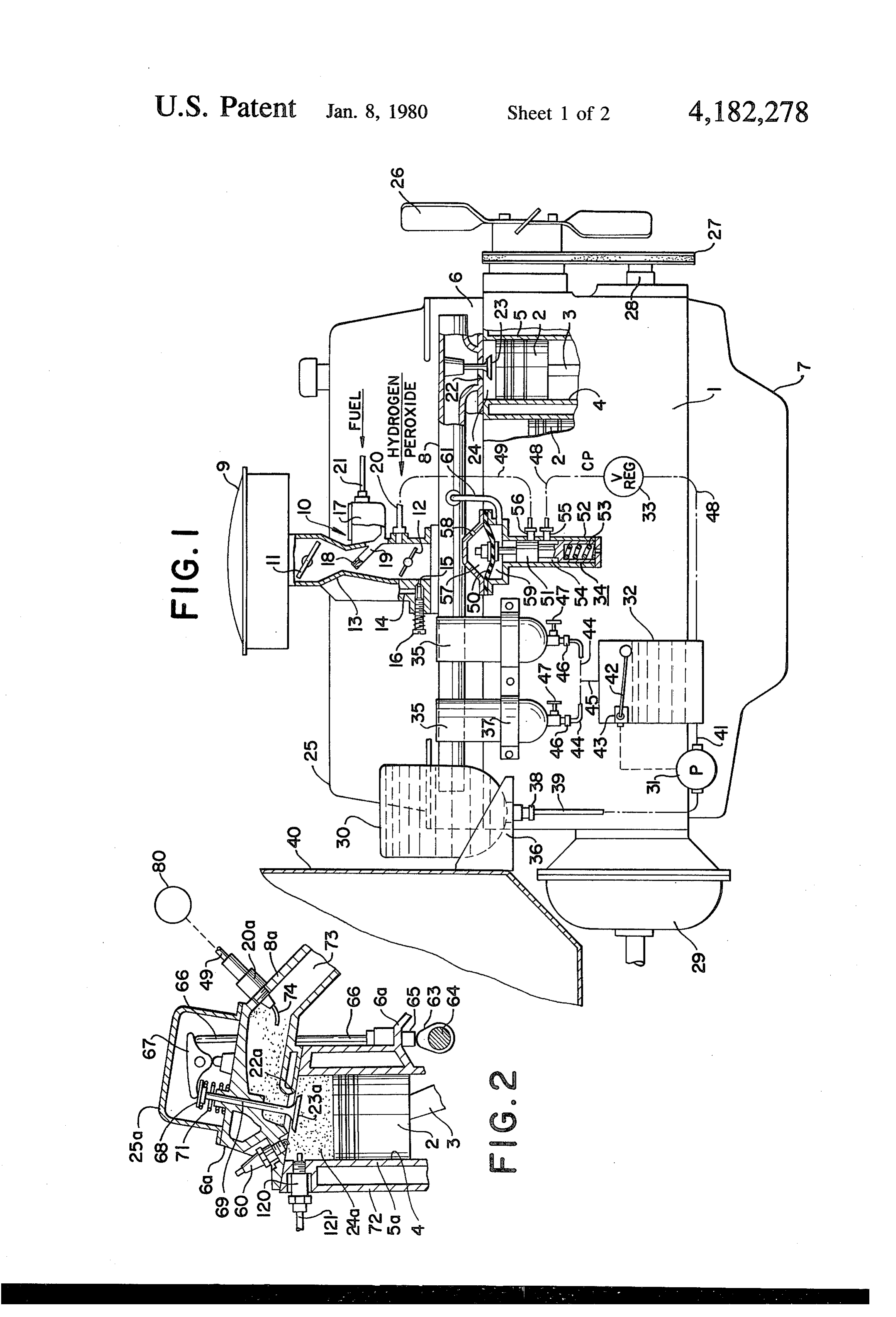
FIG. is a schematic view showing the apparatus of
BACKGROUND OF THE INVENTION 5 the present invention mounted on a conventional auto During the last decade vast sums have been spent in mobile engine;
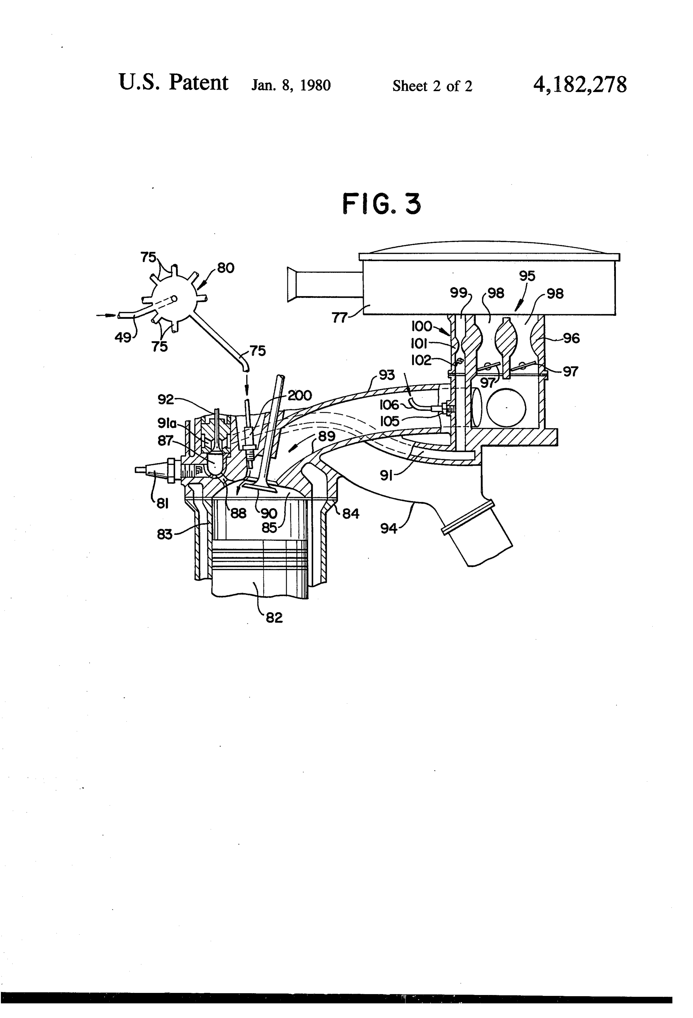
an attempt to improve the gas mileage in modern high FIG. 2 is a fragmentary vertical sectional view show compression automobile engines. Attempts have been ing a portion of an engine modified to employ the appa made to operate the engines with lean fuel-air mixtures 10 ratus of this invention; and 3 is a fragmentary vertical sectional view show and lead-free gasoline, but it has been difficult to obtain ing another satisfactory performance in this way because of ignition Honda-type embodiment of the invention as applied to a engine with an auxiliary combustion cham or combustion problems when the air-fuel ratio is high, ber for torch ignition.
particularly when it exceeds 17 to 1. It is also difficult to avoid knocking and to achieve good all around perfor 15 DESCRIPTION OF PREFERRED mance in lean-burn engines using lead-free or low oc EMBODIMENTS tane gasoline and compression ratios such as 9:1 to 10:1 The process of the present invention may be applied or higher. to any conventional high-compression automobile en Ignition problems are less severe in a lean-burn en gine and particularly the common reciprocating-piston gine when torch ignition is employed as in Honda-type 20 internal combustion engine. FIG. 1 illustrates one em engines which have the spark plug located in an auxil bodiment of the invention wherein the invention is ap iary combustion chamber. However, the combustion plied to a conventional in-line, four-stroke, six cylinder, problem is still a limiting factor and the engines cannot overhead-valve automobile engine A having a cast iron operate satisfactorily with an air-fuel ratio of 20 to 1. cylinder block 1 with pistons 2 arranged to drive the The large amounts of nitrogen apparently interfere with 25 crankshaft (not shown) through connecting rods 3. The proper combustion. pistons reciprocate in the vertical cylindrical bores 4 of
Summary of the invention
the cylinder walls 5 which are cooled by water or other liquid coolant from the radiator (not shown). A conven
The present invention solves the above problems by 30 tional cylinder head 6 is mounted on the top of the injecting a nitrogen-free oxidizing fluid, such as hydro engine block 1, and an oil pan 7 is mounted on the bot gen peroxide, into the engine. This combined with tom of the block. An intake manifold 8 and an exhaust water injection makes it possible to operate a modern manifold (not shown) are mounted on the cylinder high-compression engine at a high air-fuel ratio, such as head. The air passes through an air cleaner 9 to a carbu 18:1 to 20:1, when using lead-free or low octane fuel. 35 retor 10, where it is mixed with fuel, and the air-fuel The invention applies to all types of internal combus mixture passes to the intake manifold. The carburetor tion engines and can be employed to modify existing receives gasoline from the fuel pump (not shown) engines. For example, an existing automobile can be through a fuel line 21. The flow of air is controlled by a choke valve 11 and a throttle valve 12 and the fuel modified by adjusting or changing the main discharge flow is regulated by the carburetor in the conventional jet to provide a leaner fuel-air mixture and by providing manner means for injecting water and hydrogen peroxide into meteringbymeans. means of a Venturi 13 and associated fuel the carburetor in accordance with engine load. The flow of the hydrogen peroxide may be easily regulated tionThe(except carburetor 10 may be of conventional construc for the auxiliary discharge nozzle 20) and by a valve responsive to movement of the gas pedal or may, for example, throttle valve or responsive to intake manifold pressure. 45 the type commonlybeused a standard Carter carburetor of A continuous supply of hydrogen peroxide can be last 2 decades. As shown, inthepassenger cars during the carburetor has the usual maintained by providing a high pressure mixing tank idle air passage 14 and idle discharge passage containing water and hydrogen peroxide and by supply idle adjusting screw 16 which may be turned to15enlarge and an ing pure oxygen to the top of the tank from one or more or restrict the opening at the discharge passage. The oxygen tanks.
Optionally, oxygen from the tanks may be introduced latter passage is located at or slightly below the throttle valve when the valve is closed, and the air-fuel mixture into the combustion chamber of each cylinder to pro passing through passage 14 is preferably somewhat rich mote ignition during starting or operation of the engine. to facilitate idling at low speeds and starting the engine. The invention is also applicable to lean-burn Honda The carburetor 10 has the usual float chamber hous type engines having an auxiliary carburetor and having 55 ing 17 providing a reservoir of fuel and containing a an auxiliary combustion chamber for each cylinder. The float to maintain the fuel at the proper level. A main torch ignition principle plus hydrogen peroxide injec discharge jet 18 is located within the Venturi 13 at the tion into the main carburetor or into the main combus upper end of an inclined discharge tube 19 which ex tion chamber makes it possible to operate with ex tends from the bottom of the float chamber. The tube tremely high air-fuel ratios. 60 may contain a metering orifice to regulate the flow of The process of this invention improves the efficiency fuel, and the fuel flow is such as to provide a lean air of the engine and minimizes air pollution. It permits use fuel mixture for normal engine operation. of lead-free gasoline, gasolines of various octane ratings, In accordance with the present invention the carbure and various gasoline mixtures. The gasoline may be tor is constructed and/or adjusted to provide a higher mixed with substantial amounts of alcohol or with small 65 air-fuel ratio than would be provided by the main dis amounts of various other fuels such as a nitroparaffin, a charge jet 18 according to conventional practice and a naphthene or an olefin; but conventional gasolines are special discharge nozzle 20 is provided for injecting an usually preferred. oxidizing agent, such as hydrogen peroxide. The inven 5 tion is illustrated as applied to a conventional downdraft valve operated by a diaphragm 50 responsive to intake carburetor, but it will be understood that other types of manifold pressure. The valve has a spool valve member carburetors can be used. 51 connected to the diaphragm and mounted to recipro The invention may be applied to various types of cate in a cylinder 52. The bottom portion of the valve engines including rotary engines and compression igni 5 member has a recess to receive a spring 53 and the tion engines, but is shown applied to a simple spark-igni middle portion has an annular peripheral groove 54 tion engine having cam-operated intake and exhaust with an axial length sufficient to establish communica valves for each cylinder. As shown the intake valve 23 tion between the inlet opening 55 and the outlet opening is arranged to move into and out of contact with the 56 when the valve is in the open position. valve seat 22 to admit the air-fuel mixture from the 10 The diaphragm 50 is mounted in a housing having an intake manifold 8 to the combustion chamber 24 of each upper chamber 57 with a vent opening 58 and a lower cylinder. The valve actuating means is located under chamber 59 with a conduit 61 connected to the intake the valve cover 25 and may, for example, be of the manifold 8. At low loads with the throttle 12 near the general type illustrated in FIG. 2. closed position, the subatmospheric pressure in the in The engine shown herein is a standard type of water 15 take manifold and in the chamber 57 causes the dia cooled automobile engine with a fan 26 driven from the phragm 50 to move downwardly and compress the crankshaft by a fan belt 27 and water-pump pulleys 28. spring 53, thereby closing the outlet 56 as indicated in The engine has a transmission 29 and is mounted in an FIG. 1. Under high load with the throttle 12 opened automobile having a firewall 40. wide, the pressure in the intake manifold increases and In accordance with the invention, auxiliary means are 20 the difference in pressure between chambers 57 and 59 provided for supplying hydrogen peroxide to the en decreases so that the spring 53 can move the valve to gine which may include a liquid supply tank 30, a mo the open position and admit liquid from conduit 48 to tor-driven injection pump 31, a mixing tank 32, valves conduit 49. Thus liquid is injected through the nozzle 20 33 and 34, and a pair of oxygen tanks 35.
The tanks 30 and 35 are removable and are shown as 25 whenever the engine is operated under a high load, for being supported in inverted positions by suitable brack up example when the automobile is accelerating or going ets 36 and 37, respectively. The tank 30 has a fitting 38 a hill.
detachably connected to a supply conduit 39 which described The process of operating the engine of FIG. 1 is in more detail hereinafter, it being understood extends to the inlet of pump 31. The pump discharges to that such process can be applied to engines quite differ the tank 32 through discharge conduit 41 and maintains ent from those illustrated a high pressure on the liquid in the tank. herein. The motor of the pump may be controlled in accor FIG. 2 is a fragmentary view showing another em dance with the liquid level and/or the pressure in the bodiment of the invention wherein the hydrogen perox tank 32 to maintain the necessary liquid pressure. As ide head or other oxidizing agent is injected at the cylinder rather than into the carburetor. The four-stroke herein shown, a float 42 and a float-operated control 35 unit 43 are provided for controlling operation of the internal combustion engine of FIG. 2 may be of essen pump 35 to maintain a constant liquid level in the mix tially the same type as the engine of FIG. 1 and each ing tank 32. Where the pump is driven by an electric shown in may cylinder have generally the same basic elements
FIG. 2 plus a conventional exhaust valve (not motor, the unit 43 may start and stop the motor in ac cordance with the position of the float. shown), in the cylinder head 6a. The piston 2 of each As shown, a pair of oxygen tanks 35 are provided for cylinder reciprocates in the bore 4 of the cylinder wall supplying oxygen to the upper part of the tank 32 5a within the cooling jacket 72 to drive the crankshaft through the conduits 44 and 45. Each tank has a fitting which in turn drives the cam 63 and camshaft 64 46 detachably connected to the associated conduit 44 through timing chains (not shown). The cam effects and a valve 47 for controlling flow of oxygen from the 45 operation of the intake and exhaust valves in the usual tank. The second oxygen tank is optional but is pre ane, ferred. As shown the valve operating means is of a conven The pressure in the tanks 35 may be 20 to 50 atmo tional type including tappets 65, push rods 66 and spheres or higher, and the mixing tank 32 is designed to rocker arms 67 located under the valve cover 25a. The withstand such pressures. The pressure on the liquid 50 end portion of each rocker arm engages the flat end must be reduced before it is injected into the carburetor member 68 carried by the valve stem 69 and moves the 10, and a pressure reducing means is provided for this intake valve 23a out of contact with its seat 22a by purpose. For example, a constant pressure valve 33 may compressing the valve spring 71. Opening of the intake be provided in the conduit 48 leading from the tank 32 valve admits the air-fuel mixture form the passage 73 of to maintain the pressure at the outlet side of the valve 33 55 the intake manifold 8a to the combustion chamber 24a at a predetermined value, such as 5 to 10 pounds per where it may be ignited by a spark plug 60 at or after the square inch. The valve 33 is responsive to the outlet end of the compression stroke. A wedge-shaped com pressure and closes when that pressure exceeds said bustion chamber is shown in FIG. 2 but various other predetermined value. shapes can be employed.
The control valve 34 is provided between the conduit 60 In accordance with the invention, the hydrogen per 48 and the conduit 49 to regulate the flow of liquid to oxide from conduit 79 is injected from a suitable distrib the discharge nozzle 20 at the end of conduit 49. The utor through injector member 20a into the air-fuel mix valve 34 may be opened and closed in response to ture entering the combustion chamber in timed relation movement of the throttle valve 2 or in response to the with the crankshaft as described in more detail hereinaf pressure in the intake manifold 8 so that hydrogen per 65 ter. Said injector. member may be located to inject di oxide and water are injected into the carburetor when rectly into its associated cylinder or to inject into the the throttle A2 is opened and the engine is under high cylinder head and may be located in the cylinder head. load. As herein shown, the valve 34 is a spool-type As shown it is spaced from the intake valve 23a and has 6 a curved discharge tube 74 which directs the liquid the intake passages 98 to the intake manifold 93. The toward the valve stem 69. carburetor 95 can be adjusted to provide a lean fuel-air As shown in FIG. 2, the electrodes of the spark plug mixture (for example, an air/fuel ratio in excess of 17:1). 60 are located at the bottom face of the head 6a and at A minor portion of the intake air passes through a a point farthest from the piston 2 so that ignition starts second carburetor 100 with an intake passage 99 which at the uppermost portion of the combustion chamber. is small relative to the passage 98. The auxiliary carbu Optionally, oxygen or an oxygen-rich gas can be in retor has a small Venturi 101 and a small throttle valve jected adjacent the spark plug electrodes during the last 102 for controlling flow to the intake passage 91 of the part of the compression stroke to facilitate ignition of a auxiliary intake manifold, and the carburetor 100 is lean mixture. The optional injection nozzle 120 may be 10 adjusted to provide a richer fuel-air mixture (for exam positioned adjacent the spark plug 60 of each cylinder ple, an air-fuel ratio less than 16:1). to admit metered amounts of pure oxygen to the com The throttle valves 97 and 102 are operated simulta bustion chamber 24a from a supply conduit 121 con neously and may have dual controls or synchronized nected to a source of oxygen, such as the oxygen tanks controls as disclosed, for example, in U.S. Pat. No. 35. The process is described in more detail hereinafter. 15 3,830,206 or as commonly used in automotive vehicle The present invention involves a process for operat engines. Likewise the intake valves 90 and 92 of each ing engines of various types and is particularly well cylinder may be operated in the desired sequence using suited for four-stroke internal combustion engines of the conventional valve-operating mechanisms, such as dis type used in "Honda' automobiles having an auxiliary closed in U.S. Pat. Nos. 3,830,205 and 3,853,097. combustion chamber for effecting "torch ignition'. An 20 The engine of FIG. 3 may be a standard type of engine of this type is shown and described in U.S. Pat. Honda engine, such as a four-stroke four cylinder auto No. 3,832,984 and is illustrated in FIG.3 hereof. Similar mobile engine designed to operate with standard gaso engines with auxiliary combustion chambers having a line; however, the engine is modified in accordance common assignee (Honda) are disclosed in U.S. Pat. with this invention by adding auxiliary means for inject Nos. 3,830,205; 3,830,206; 3,853,097; 3,837,322; 25 ing an oxidizing agent and for increasing the amount of 3,852,379; and 3,844,259; and it will be understood that oxygen available for combustion and by adjusting the the various cam mechanisms, carburetors, and fuel feed carburetor to provide a leaner fuel-air mixture. ing mechanisms disclosed in these patents or used in The engine may, for example, be modified by inject modern Honda automobiles may be incorporated in an ing an oxidizing agent, such as hydrogen peroxide, into engine which is used to practice the present invention as 30 the main combustion chamber 85 or into the main car will be apparent from the description of this invention. buretor 95. The injection means may, for example, be FIG. 3, which is employed for purposes of example, similar to the General Motors fuel injection system shows a Honda-type four-stroke internal combustion illustrated on page 407 of "Internal Combustion En engine having a series of pistons 82 mounted in the gines' (Third Edition) by Edward F. Obert, published cylinders 83 of a water-cooled engine block 84. The 35 1968 by International Textbook Company. In that sys basic engine may have 4 to 8 cylinders, for example, and tem a distributor or fuel divider (corresponding to the may be of conventional construction. Each cylinder of distributor 80 herein) supplies fuel periodically to a the cylinder head 86 has a main combustion chamber 85 series of nozzles, each located in an inlet port and aimed and has a small auxiliary combustion chamber 87 which at an inlet valve.
opens to the spark plug 81. A torch nozzle or passage 88 40 As herein shown, a nozzle 200 is located near and extends between the chamber 85 and the chamber 87 to above each intake valve 90 and directs the hydrogen permit the flame to ignite the lean mixture in the main peroxide solution toward the head of the valve 90 and combustion chamber. toward the intake port opening. The hydrogen peroxide Respiration of the Honda-type engine is provided by and water are supplied from a suitable source such as a three valved ports. A lean air-fuel mixture is periodi 45 hydrogen peroxide tank or an apparatus as shown in cally provided to the main combustion chamber 85 FIG. 1 and the distributor or liquid divider 80 may be through a main intake passage 89 of the intake manifold connected to the discharge end of the conduit 48 or 49 93. The flow through passage 89 is controlled by the of FIG. .
main intake valve 90. A rich air-fuel mixture is periodi The distributor 80 may be essentially the same as that cally provided to the auxiliary combustion chamber 87 50 employed in the General Motors fuel-injection system through an auxiliary intake passage 91. A small auxiliary described above and has a conduit 75 extending to the intake valve 92 controls flow to the chamber 87. A nozzle 200 of each cylinder. Eight are provided for a conventional exhaust valve (not shown) controls the V-8 engine and four are provided for a four-cylinder exhausting of the burned gases from the cylinder 83 to Honda engine. The distributor is driven by the engine in the exhaust manifold 94. If desired, heat from the ex 55 timed relation thereto and causes metered amounts of haust manifold may be employed to preheat the air-fuel the liquid to be injected into each cylinder at a predeter mixture from the carburetor as disclosed in said U.S. mined time during the intake stroke while the intake Pat. No. 3,832,984. port is open as shown in FIG. 3, for example during the The flame generated in the auxiliary chamber 87 half of the intake stroke and before the valve 90 closes. effects ignition of the lean mixture in the main combus The pressure on the hydrogen peroxide solution sup tion chamber 85 and makes possible substantial savings plied to the distributor is high enough to provide the in fuel and less air pollution. desired flow rate through the nozzle 200 and may be In the engine of FIG.3 a special carburetion system regulated by a suitable valve, such as the valve 33 of is required to supply the lean and rich fuel-air mixtures FIG. 1. The flow may also be regulated by manifold required for the chambers 85 and 87, respectively. As 65 pressure to reduce flow under low load conditions using shown most of the air from the air cleaner 77 passes a diaphragm operated valve, such as the valve 34. through a main dual carburetor 95 having two Venturis Optionally pure oxygen or a gas rich in oxygen can be 96 and two throttle valves 97 controlling flow through injected into the auxiliary carburetor 100 or the auxil 7 iary intake passage 91 to facilitate ignition in the auxil provide pure oxygen at the top of the mixing tank 32 iary combustion chamber 87. As shown, an optional and to maintain the tank under a high pressure so that nozzle 105 is provided below the carburetor 100 to hydrogen peroxide is formed and maintained at the receive oxygen from conduit 106 which can be con required concentration. The high pressure oxygen can nected to a suitable oxygen source, such as the oxygen react with the water to form hydrogen peroxide and its tanks 35. The oxygen injection makes it possible to presence reduces the reverse reaction so that the hydro obtain satisfactory ignition in the chamber 87 with the gen peroxide has less tendency to decompose during carburetor 100 adjusted to provide a somewhat leaner storage in the mixing tank. If desired, means may be mixture, and is a possible way to facilitate starting or to provided for agitating the liquid in the tank 32. effect fuel savings. It may also have advantages when O As shown, the tank 30 is removable, but it will be using special fuel mixtures such as mixtures of alcohol understood that it may have an opening at the top so and gasoline. that the water or a solution of water and alcohol or It will be understood that the distributor 80 is not water and hydrogen peroxide may be poured into the needed if the hydrogen peroxide solution is introduced tank.
into the main carburetor as in the embodiment of FIG. 15 . The oxygen tanks 35 can be at a high pressure, such 1. as 20 to 100 atmospheres or higher, to facilitate reaction In carrying out the process of this invention in a of the oxygen with the water in tank 32 and to maintain standard automobile engine, such as illustrated in FIG. the desired concentration of hydrogen peroxide. In the l, it is preferable to adjust the carburetor so that the event the concentration becomes lower than desired main discharge jet 18 provides a lean mixture and so because of inadequate pressure or for any other reason, that the idling discharge at 15 provides either a rich additional hydrogen peroxide can be introduced from mixture or a mixture rich enough to permit satisfactory tank 30. If the concentration of hydrogen peroxide in idling of the engine, for example at speeds of 400 to 800 tank 30 is high, a separate water tank may be provided revolutions per minute. For example, the air-fuel ratio to supply water for dilution in the mixing tank. during idling may be less than 15 to 1. 25 By providing two oxygen tanks, it is possible to re By injecting an oxidizing agent and water into the place either tank at any time without loss of oxygen or carburetor it becomes possible to obtain satisfactory loss of pressure in tank 32.
operation of the engine with a carburetor setting which The apparatus for providing hydrogen peroxide to would otherwise be unsatisfactory because of ignition the Honda-type engine of FIG.3 may, of course, be the problems or engine knocking with the particular fuel 30 same as illustrated in FIG. I. In accordance with this being used. Use of an oxidizing agent, such as hydrogen invention, the engine of FIG. 3 is operated in such a peroxide, makes it possible to reduce fuel cost and to manner as to reduce the amount of fuel supplied to the reduce air pollution by using a leaner mixture with an carburetor 95 and increase the air-fuel ratio to a high engine of a given compression ratio, a more economical value, such as 18:1 to 20:1, while periodically injecting fuel mixture, and/or a higher compression ratio. 35 through the nozzle 200 a hydrogen peroxide solution For example, in accordance with one embodiment of consisting of water and hydrogen peroxide. The solu the invention, an engine with a compression ratio from tion may contain a small amount of alcohol. 9:1 to 10:1 has the carburetor 0 adjusted to provide a The distributor 80 causes the flow of hydrogen per lean mixture with an air-fuel ratio from about 17:1 to oxide and water to each cylinder to occur only during about 20:1 during operation at normal load. Such an 40 the intake stroke while the intake valve 90 is open and engine may be operated with low-lead gasoline having cuts off the flow when the valve is closed. The amount an octane rating somewhat lower than that of the more of hydrogen peroxide injected varies with engine load commonly used "regular' gasolines because of the anti and may be generally proportional to the amount of fuel knock properties of the water injected with the hydro supplied to carburetor 95. It is sufficient to provide the gen peroxide. 45 air-fuel mixture in the combustion chamber 85 with the In the preferred process, the amount of hydrogen necessary combustion characteristics. Various means peroxide injected into the engine is regulated in accor may be employed to increase or decrease the rate of dance with engine load and reduced when the fuel flow flow of the hydrogen peroxide solution in accordance is reduced. This is conveniently accomplished by the with the fuel flow to carburetor 95 or the position of the apparatus of FIG. 1 using manifold pressure to regulate SO throttle valves 97. This can be conveniently handled by the flow of hydrogen peroxide to nozzle 20. The using intake manifold pressure to control the flow as amount of hydrogen peroxide required depends on the disclosed in FIG. E.
air-fuel ratio, and for example, is more when that ratio In the embodiment illustrated in FIG. 3, the hydro is 20:1 than when the ratio is 18:1. In order to employ gen peroxide must be injected before the end of the the maximum air-fuel ratio it is desirable to provide a 55 intake stroke while the intake valve is open, but it will very effective ignition system such as that of FIG. 3, but be understood that the hydrogen peroxide may be in it will be understood that torch ignition is not essential. jected under high pressure directly into the cylinder The hydrogen peroxide may be supplied in various while the intake and exhaust valves are closed using an ways. Part or all of it may be manufactured on the injection pump of the type used for fuel injection. Di vehicle or part may be provided by containers filled 60 rect injection is more complicated than port injection with hydrogen peroxide. For example, small tanks may but may have some advantages. For example, direct be purchased from commercial manufacturers contain injection of the hydrogen peroxide solution during the ing 20 to 80 percent hydrogen peroxide. compression stroke or at the beginning of the power As shown in FIG. 1, a mixing tank 32 is provided for stroke may be advantageous.
the hydrogen peroxide solution and the solution is main 65 The injection of an oxidizing fluid, such as hydrogen tained under pressure. The hydrogen peroxide and peroxide, into the main combustion chamber 85 makes it water may be supplied to the tank 32 from the supply possible to achieve combustion of a very lean air-fuel tank 30 or any other source. It may be preferred to mixture and to employ air-fuel ratios of about 20:1 be 8 cause the additional oxygen promotes rapid flame prop provide a lean-burn engine with more power while it is ogation. accelerating or under high load conditions. Heretofore it was difficult to ignite a very lean air When modifying an existing standard engine, it is fuel mixture, and the inert gas, nitrogen, tended to sup contemplated that the carburetor setting would be press combustion. One way to reduce the ratio of nitro changed to increase the air fuel ratio substantially (e.g., gen to oxygen is to add pure oxygen or an oxidizing 10 to 20 percent or more) and that the amount of hydro agent, such as hydrogen peroxide. The addition of addi gen peroxide solution introduced into the engine would tional oxygen in this manner to increase the ratio of be sufficient to promote effectively the combustion of reactive oxygen to fuel substantially (e.g., at least 5 to 10 the lean mixture. For example, under high load the flow percent) makes it possible to achieve combustion with 10 of the hydrogen peroxide solution to the engine could be 5 to 10 percent or more of the gasoline flow. The leaner mixtures, to save fuel and to reduce air pollution engine by achieving more complete combustion. may, for example, require 1 to 2 gallons or more The process of this invention may, for example, be of the hydrogen peroxide solution for each 10 to 20 applied to a standard V-8 or 6-cylinder four-stroke auto gallons of gasoline depending on the hydrogen peroxide mobile engine having a compression ratio of around 15 concentration and other factors.
9.5:1 and designed to operate with the usual "low-lead” The process of this invention is versatile and makes it or "regular' gasoline, such as manufactured by Ford, possible to regulate a lean-burn engine with simple or General Motors or Chrysler. The carburetor is adjusted computerized controls so that it can operate satisfacto at the main metering jet to increase the air-fuel ratio 10 rily under many different conditions. For example, the to 15 percent or more to 18:1 or greater and an aqueous 20 amount of water and/or alcohol and the amount and solution of 20 to 30 percent hydrogen peroxide is fed to concentration of the hydrogen peroxide or other oxidiz the carburetor in response to intake manifold pressure obtain ing fluid may be varied according to the conditions to (as in FIG. 1) in an amount sufficient to provide effec may alsooptimum performance. The auxiliary equipment be used for special purposes, such as supplying tive combustion in each cylinder so that the engine can 25 oxygen or hydrogen peroxide for starting or heating a perform satisfactorily using a common gasoline such as cold engine, for providing temporary power increases, Shell “regular" or Sunoco 190 or a typical low-lead or for removing carbon deposits. gasoline sold in service stations by the major oil compa The present invention also contemplates various al
The process may also be used on a 1976 or 1977 four ing fluid or oxidizing agent introduction ternate procedures, such as of the oxidiz with the gasoline or other cylinder Honda engine of the general type represented 30 fuel entering the engine or the carburetor. In an engine by FIG. 3 having torch ignition. The main carburetor wherein the fuel is injected directly into each cylinder, would be adjusted to increase the air-fuel ratio at least the hydrogen 10 percent over that for which the engine was designed injected with orperoxide mixed or other oxidizing fluid can be with such fuel. If fuel is injected and a hydrogen peroxide solution would be introduced 35 into a small auxiliary combustion chamber of each cyl into the air-fuel mixture from the carburetor as in the previous example in an amount sufficient to provide 4,038,952, an optional procedure is toinintroduce inder as disclosed, for example, U.S. Pat. No.
hydro effective combustion in the main combustion chamber gen peroxide into each auxiliary combustion chamber of each cylinder when common gasolines are used, such with the fuel to promote ignition during starting or as mentioned in the previous example. 40 during normal operation and/or to permit increase in When the Honda engine is so modified, the air-fuel the air-fuel ratio in the auxiliary combustion chamber or ratio in each auxiliary combustion chamber is usually in the main combustion chamber.
substantially less (e.g., at least 20 percent less) than that The invention may be applied to various types of in the main combustion chamber. However, savings in lean-burn engines including those having recirculation fuel can sometimes be effected by increasing the fuel-air 45 of engine exhaust as in U.S. Pat. No. 4,041,916 or other ratio in each auxiliary combustion chamber, and oxygen special features, such as disclosed in U.S. Pat. Nos. can be introduced to that chamber from an oxygen tank 4,023,543; 4,040,393 or 4,041,923. The lean-burn engines as disclosed in FIG. 3, for example, to facilitate starting may employ various means to promote ignition other or to reduce the probability of poor ignition under diffi than auxiliary combustion chambers, for example as cult conditions. 50 disclosed in U.S. Pat. No. 4,041,922. While some advantages of the present invention are As used herein, the term "oxidizing fluid' or "oxidiz obtained when the hydrogen peroxide solution injected ing agent' excludes air or a gas containing major into the engine consists of only 10 percent by weight of amounts of nitrogen.
hydrogen peroxide, up to 90 percent by weight of wa The term air-fuel ratio means the ratio of the rate of ter, and up to 10 or 20 percent of alcohol, the hydrogen 55 flow by weight of air to the rate of flow of fuel and as peroxide solution usually contains 20 to 40 percent or used herein excludes oxygen provided to the cylinder more of hydrogen peroxide. from the hydrogen peroxide solution. The invention is particularly well suited for modifica It will be understood that all percentages given tion of an existing standard high-compression automo herein are by weight unless the context shows other bile engine, for example having a compression ratio 60 W1Se.
from about 9:1 to about 10:1, because all that is needed It will be understood that, in accordance with the is simple auxiliary equipment which can be readily patent laws, variations and modifications of the specific mounted on the engine. Because the water injected into methods and devices disclosed herein may be made the engine reduces the tendency for engine knock, it without departing from the spirit of the invention. becomes possible to employ lead-free gasoline or gaso 65 Having described my invention, I claim: line having a lower octane rating than would otherwise 1. A process of operating a four-stroke high-compres be required. If the water is mixed with a fuel, such as sion reciprocating-piston internal combustion engine methanol or other alcohol, the water injection can also having a series of cylinders, means for supplying ambi 9 ent air from outside the engine to said cylinders, means reaction in said tank to maintain a supply of hydrogen for supplying fuel to said engine to maintain the air-fuel peroxide.
ratio within a predetermined range, intake and exhaust 7. A process of operating a four-stroke high-compres valves for controlling the flow of gases to and from sion reciprocating-piston internal combustion engine each cylinder, and means for igniting the air-fuel mix having a series of cylinders, means for supplying ambi ture in the main combustion chamber for each cylinder, ent air from outside the engine to said cylinders, means said engine having a compression ratio of at least 9:1 for supplying fuel to said engine to maintain an air-fuel and being designed for normal operation with low-lead ratio within a predetermined range, intake and exhaust gasoline with the air-fuel ratio below 17 to 1, said pro 10 valves each for controlling the flow of gases to and from cylinder, and torch means for igniting the air-fuel cess being characterized by the steps of mixture in the main combustion chamber for each cylin (a) modifying the flow of air and gasoline to the en der including a small auxiliary combustion chamber, a gine to increase the air-fuel ratio in the main com combustible mixture being supplied to the auxiliary bustion chamber of each cylinder at least 10 per chamber of each cylinder having an air-fuel ratio at cent to at least 18 to 1 and high enough to create 15 least 20 percent less than that of the air-fuel mixture ignition problems when the engine is under high supplied to the main combustion chamber, said process load, being characterized by the steps of (b) introducing into each cylinder while the engine is (a) modifying the flow of air and fuel to the engine to under high load a solution of hydrogen peroxide to increase the air-fuel ratio in the main combustion cause it to mix with the air-fuel mixture in the main 20 chamber of each cylinder at least 10 percent to at combustion chamber, and least 20:1, whereby the engine tends to malfunction (c) regulating the flow of hydrogen peroxide to the under high load, engine cylinders in accordance with intake mani (b) introducing into each cylinder while the engine is fold pressure and engine load, the weight rate of under high load a solution of hydrogen peroxide flow of said hydrogen peroxide being at least 5 25 and water to cause it to mix with the lean air-fuel percent of that of the fuel and sufficient to promote mixture in the main combustion chamber, and effective combustion in the main combustion (c) regulating the flow of the hydrogen peroxide chamber of each cylinder during high-load opera solution to the engine cylinders in accordance with tion. engine load, the weight rate of flow of said hydro 2. The process of claim 1 wherein said solution con gen peroxide solution being at least 10 percent of tains at least 20 percent by weight of hydrogen peroxide that of the fuel.
and the rate of feed of said solution to each cylinder by 8. The process of claim 7 wherein an additional fuel, volume is at least 10 percent of that of said fuel when such as alcohol, is mixed with the water and hydrogen peroxide to provide additional power under high load the engine is under heavy load.
3. The process of claim 1 wherein each cylinder has a 35 conditions.
small auxiliary combustion chamber containing ignition ing9. fluid The process of claim 7 wherein an auxiliary oxidiz is introduced into the auxiliary combustion means and a combustible mixture is supplied to said chamber to facilitate operation of the engine under combustion chamber having an air-fuel ratio at least 20 adverse conditions.
percent less than that of the air-fuel mixture supplied to 10. The process of claim 7 wherein a carburetor is the main chamber.
4. The process of claim 1 wherein hydrogen peroxide provided for supplying the air-fuel mixture to the main combustion chamber of each cylinder and hydrogen and additional fuel are introduced into each cylinder to peroxide is supplied to the air-fuel mixture flowing from provide additional power for acceleration under ex the carburetor to the cylinders.
treme load conditions. 45 11. The process of claim 10 wherein a mixture of 5. The process of claim 1 wherein a mixture of hydro hydrogen peroxide and fuel is supplied to the carbure gen peroxide and water is stored under high pressure in tor.
a mixing tank and is supplied from said tank to the en 12. The process of claim 10 wherein a separate carbu gine at a reduced pressure, and high purity oxygen is retor is provided for supplying a rich mixture to the supplied to said mixing tank from at least one oxygen 50 auxiliary combustion chamber of each cylinder and tank. oxygen is supplied to the auxiliary combustion chamber 6. The process of claim 5 wherein water and oxygen from an oxygen tank. x 38 are supplied to said mixing tank at a high pressure for
Provenance
- Collection
- Patents citing this work
- Pages
- 9
- Method
- pdftotext (the PDF's own text layer) + pdftoppm 300dpi page scans
- Patent office record
- patents.google.com →
- Source
- Google Patents citing-documents table
- Assignee
- Coakwell Charles A
- Published
- 1980-01-08
- Transcribed from
- patentimages.storage.googleapis.com →