

patent · US4183506A
Protective device for turbine driven by exhaust gas from blast furnace
15 January 1980
Text
Page 1scan →
United States Patent (19)
Teshima et al.
(54) protective device forturbine
Driven by exhaust gas from blast
Furnace
(75) Inventors: Kiyomi Teshima; Yukimasa Kajitani, both of Tamano, Japan 73 Assignees: Mitsui Engineering & Shipbuilding
Co., Ltd.; Nippon Steel Corporation, both of Tokyo, Japan
51 int. C.’.............................................. C21D 11/00 (52) U.S. C. ..................................... 266/88; 60/39.55;
(58 Field of Search ............................ 60/39.54, 39.55;
2,995,895 8/1961 Howes ............................... 60/39.55 3,304,074 2/1967 Atherton .......................... 266/197 X 3,747,335 7/1973 Strub ................................ 266/97 X 3,832,845 9/1974 Aguet ............................. 60/39.55 X
4,067,557 1/1978 Inubushi et al. ....................... 266/89
Foreign patent documents
391.80 2/1973 U.S.S.R. ......... ... . . . . . . . . . . . . . . . . . . . . . . . 266/89
Primary Examiner-Paul A. Bell
Attorney, Agent, or Firm-Armstrong, Nikaido,
Marmelstein & Kubovcik
A device for protecting a turbine driven by an exhaust gas of a blast furnace from a high temperature gas gen erated and discharged when the blow-out phenomenon takes place in the blast furnace is disclosed. In this pro tective device, occurrence of the blow-out phenomenon is detected, and cooling water is sprayed in an exhaust gas or in the turbine to lower the temperature of the gas, or cooling water is directly sprayed to a part of a mate rial which readily undergoes thermal degradation to
10 Claims, 4 Drawing Figures
Nial
Drawings
Page 2drawing sheetscan →
Page 3drawing sheetscan →
Page 4scan →
phenomenon takes place in the blast furnace, by a high
PROTECTIVE DEVICE FORTURBINE DRIVEN temperature gas instantaneously introduced into the BY EXHAUST GAS FROM BLAST FURNACE transportation passage and the turbine, the coating ma terial is thermally degraded.
BACKGROUND OF THE INVENTION 5 In the blast furnace, packed materials such as ore An exhaust gas discharged in a large quantity from a change their shapes moment by moment, and therefore, blast furnace is maintained at a high temperature and a it is impossible to prevent occurrence of the "blow-out” considerably high pressure. When the blast furnace phenomenon. Accordingly, the turbine system must be exhaust gas is washed with water in a dust precipitator designed and arranged so as to cope with this unavoida or the like disposed downstream, the temperature is 10 ble "blow-out” phenomenon.
lowered to a level approximating to ambient tempera OBJECT OF THE INVENTION ture but it still retains a sufficient pressure energy. In iron manufacturing plants, one of the important prob It is a primary object of the present invention to pro lems is how to attain the energy-saving effect how to vide a protective device for a turbine which can protect effectively recover such pressure energy possessed by a 15 the turbine and other equipments even when the blow blast furnace exhaust gas. out phenomenon takes place in a blast furnace, by main As a most conveniently workable method for recov taining the temperature of a blast furnace gas intro ery of such pressure energy, there can be mentioned a duced into the turbine and other members at a predeter method in which a turbine is driven by utilizing the blast mined level, whereby the operation of the turbine is furnace exhaust gas and a power generator is driven by 20 made possible even when the blow-out phenomenon this turbine to convert the pressure energy to electric takes place and the overall efficiency of recovery of the energy. energy by a power generator is enhanced. This energy recovery method, however, still involves Another object of the present invention is to provide problems to be solved. In the first place, the pressure or a protective amount discharged of the blast furnace exhaust gas is operation ofdevice 25 for a turbine in which if continuous not constant, but in general, it is readily changed de occurrence ofthetheturbine becomes impossible because of blow-out phenomenon in a blast fur pending on the resistance in the blast furnace, namely nace, introduction of a blast furnace gas into the turbine depending on the molten state of ore or the flow state of is interrupted by closing a shut off valve. blast furnce slag. During the operation in the blast fur nace, a part of the packed material is molten and coagu 30 BRIEF SUMMARY OF THE INVENTION lated and is often suspended in the blast furnace. When According to the present invention, the foregoing this suspended state becomes impossible to keep, the objects are attained by a protective device for a turbine coagulated mass is let to fall down and a large quantity of a high temperature gas is blown out at a time. in which occurrence of the blow-out phenomenon in a Namely, the so-called "blow-out” phenomenon is 35 blast furnace is promptly detected and in response to a caused to occur. detection signal, cooling water is sprayed in the interior In the normal operation of the blast furnace, the tem of the turbine or to a transportation pipe passage for an perature of the gas at the outlet of the blast furnace is exhaust gas disposed between the blast furnace and the 200 to 250 C. Since this high temperature is cooled by turbine, thereby to maintain the termperature of the water sprayed from a venturi scrubber or the like of a exhaust gas within a predetermined range. dust precipitator disposed between the outlet of the In general, the temperature of the blast furnace ex blast furnace and the turbine, the temperature of the gas haust gas at an inlet portion of the turbine is 60 to 80 at the inlet of the turbine is lowered to 60' to 80 C. C. but when the blow-out phenomenon takes place, it However, when the blow-out phenomenon takes place, rises to about 250 C. and simultaneously, the gas pres the temperature of the gas at the inlet of the turbine is 45 sure is elevated. Accordingly, in the present invention, elevated to 250 C. or higher. Accordingly, because of this increase of the exhaust gas temperature and/or elongation of the turbine rotor or moving blade or un elevation of the exhaust gas pressure is detected, and in even distortion of a casing, such undesirable phenome response to the detection signal, a cooling water spray non as abnormal contact of the top end of the moving ing device is operated.
blade with the casing is caused to occur or the overload 50 The position for detecting rising of the exhaust gas is imposed on the power generator. temperature or elevation of the exhaust gas pressure is Secondarily, dusts contained in the exhaust gas ad selected in view of the moving speed of the exhaust gas here to the transportation passage or the turbine, espe so that the cooling water spraying device can be oper cially a stationary blade thereof, and these dusts disturb ated without any substantial time lag from the point of gas flows and reduce the efficiency of the turbine. 55 occurrence of the blow-out phenomenon. Namely, As means for preventing adhesion and accumulation means for detecting rising of the exhaust gas tempera of dusts to the casing inlet and stationary blade of the ture or elevation of the exhaust gas pressure is disposed turbine, there is adopted a method in which parts to at the top of the blast furnace or in a piping in the vicin which dusts are likely to adhere are coated with a mate ity thereof. Electric sensing means and electric signal rial having a good parting property, such as a fluorine transmitting means are preferably used as means for resin, a phenolic resin or crystalline metal oxide ceram detecting the temperature or pressure and means for CS. transmitting a detection signal, respectively. When the interior of the turbine is coated with such Most conspicuous changes caused by the blow-out material having a good parting property, it is possible to phenomenon are those of the temperature and pressure. prevent adherence of dusts and resulting reduction of 65 In addition, the composition of the exhaust gas and the the efficiency of the turbine, but because such coating combustion state are considerably influenced by the material lacks heat resistance or readily undergoes ther blow-out phenomenon. In the present invention, means mal degradation, if the above-mentioned "blow-out' for detecting the change of the temperature and/or 5 pressure is most appropriate for detecting occurrence of cating occurrence of the blow-out phenomenon; the blow-out phenomenon, but means for detecting FIG. 3 is a sectional side view showing a gas inlet changes of such factors as the composition of the ex portion of a turbine; and haust gas and the combustion state may similarly be FIG. 4 is a diagram illustrating means for spraying adopted. 5 cooling water to a gas flow passage leading to a turbine, A water spraying device is most preferred as means by utilizing the change of the gas temperature. for cooling the high temperature exhaust gas. More DETAILED DESCRIPTION OF PREFERRED specifically, water requires a large quantity of latent EMBODIMENTS heat for evaporation, and since the exhaust gas has passed through the dust-removing step including a dust 10 FIGS. 1, 2 and 4 are systematic diagrams illustrating collector and a venturi scrubber and is then fed to the embodiments of the protective divice of the present turbine, a considerable amount of water is contained in invention for protecting a turbine driven by a blast the exhaust gas fed to the turbine and even if water is furnace exhaust gas from the blow-out phenomenon applied to the exhaust gas for lowering the temperature, caused in a blast furnace. In the drawing, a double line no particular problem or disadvantage is brought about. 15 indicates the flow system of an exhaust gas from a blast In the present invention, water may be fed in the form furnace, a solid line indicates the flow system of cooling of a mixture with an agent for protecting the interior of water, and a dot line represents an electric control cir the turbine or with other additives according to need. cuit.
In general, water spraying means is disposed at an The objects of the present invention can be attained inlet of the turbine, but it may be located at other part of 20 according to the following methods: the pipe passage.
It is preferred that water is sprayed in the atomized the(I)flow An emergency shut off valve is closed to intercept of the gas to the turbine:
state under a high pressure so that it is instantaneously (II) Cooling water is sprayed in the interior of the dispersed and gasified in the exhaust gas. The amount turbine:
sprayed of water is controlled so that the temperature of 25 (III) Cooling water is sprayed to a gas flow passage the exhaust gas fed to the turbine is maintained within the range of 60 to 80° C. However, this temperature leading to the turbine.
range differs to some extent according to the character describedthree
These methods (I), (II) and (III) will now be in detail.
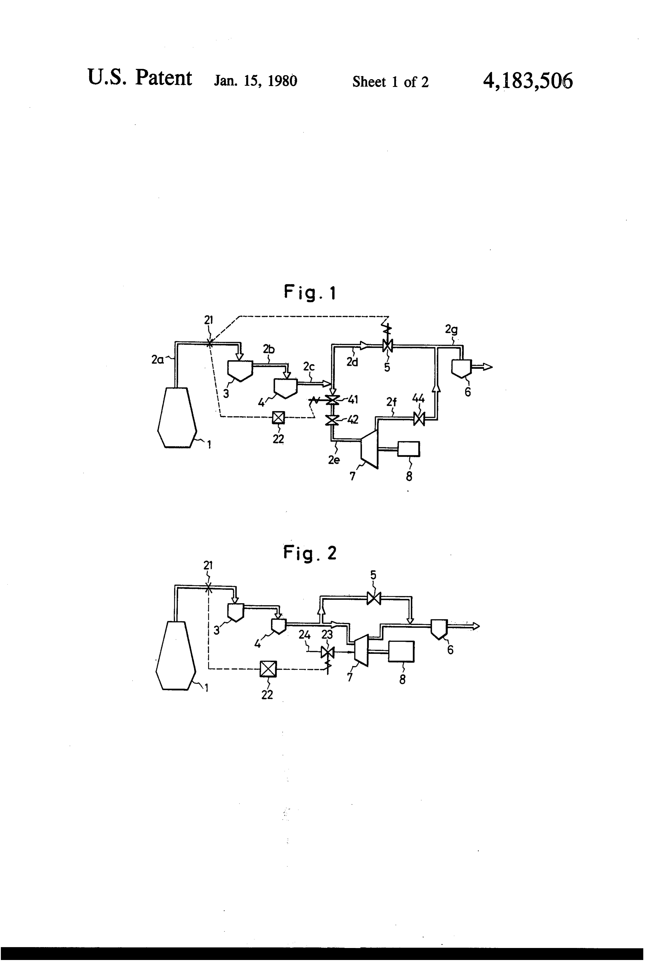
istics of the turbine and the turbine-constituting mate rial. Accordingly, the amount sprayed of water is ap 30 Referring now to FIG. 1, the method (I) is first de propriately determined depending on the turbine actu scribed. In this embodiment, an exhaust gas introduced through an exhaust gas pipe 2a connected to the top of ally employed.
When the turbine or the exhaust gas transportation aofblast dusts furnace 1 is fed to a dust collector 3 where most contained in the exhaust gas are removed there pipe passage is formed of a material insufficient in the heat resistance, water is directly sprayed to a part of 35 4 through anthe from. Then, exhaust gas is fed to a venturi scrubber exhaust gas pipe 2b. In this venturi scrub such material to prevent rising of the temperature at said part and also prevent thermal degradation of the ber 4, the exhaust gas is treated with water or a chemi material. cal solution so that it will not cause any trouble, e.g., In the present invention, since occurrence of the corrosion, at Subsequent steps. A main exhaust gas pipe blow-out phenomenon in the blast furnace is detected passage 2c is branched into a gas flow passage 2e to the and water is sprayed into the exhaust gas in response to turbine and a gas flow control passage 2d. The gas flow a detection signal, the temperature of the exhaust gas control passage 2d is extended to a second venturi can be effectively maintained at a predetermined level scrubber 6 through a septum valve 5. This second ven and hence, uneven distrotion by thermal expansion of turi scrubber 6 may be disposed just after the first ven the interior of the turbine can be prevented. Therefore, 45 turi scrubber 4. The gas flow passage 2e to the turbine is a material which readily undergoes thermal degrada connected to a turbine 7 and the exhaust gas fed to the tion, disposed in the exhaust gas transportation pipe turbine 7 is fed to the second venturiscrubber 6 through passage or turbine, can be effectively protected and the an exhaust gas flow passage 2f A power generator 8 or turbine can be stably operated at high efficiency and the other load is connected to the turbine 7, and the energy energy possessed by the exhaust gas can be effectively 50 possessed by the exhaust gas is recovered through the recovered. power generator 8 or the like. Further, if water is directly sprayed to a part where Means for detecting the temperature or pressure, thermal degradation is likely to occur, the piping system namely a temperature or pressure relay 21, is disposed can be protected efficiently. in the exhaust gas pipe 2a at a portion close to the blast Still in addition, in the present invention, if continu 55 furnace 1 and a signal generated by the relay 21 is trans ous operation of the turbine becomes impossible by the mitted through an electric control circuit 22 to control blow-out phenomenon, introduction of the exhaust gas an emergency shut off valve 41. Reference numeral 42 into the turbine can be interrupted by closing a shut off represents a governor valve for controlling the gas flow valve. to the turbine, and reference numeral 44 represents a 60 shut off valve disposed at an outlet of the turbine.
Brief description of the drawing
In the protective device having the above structure,
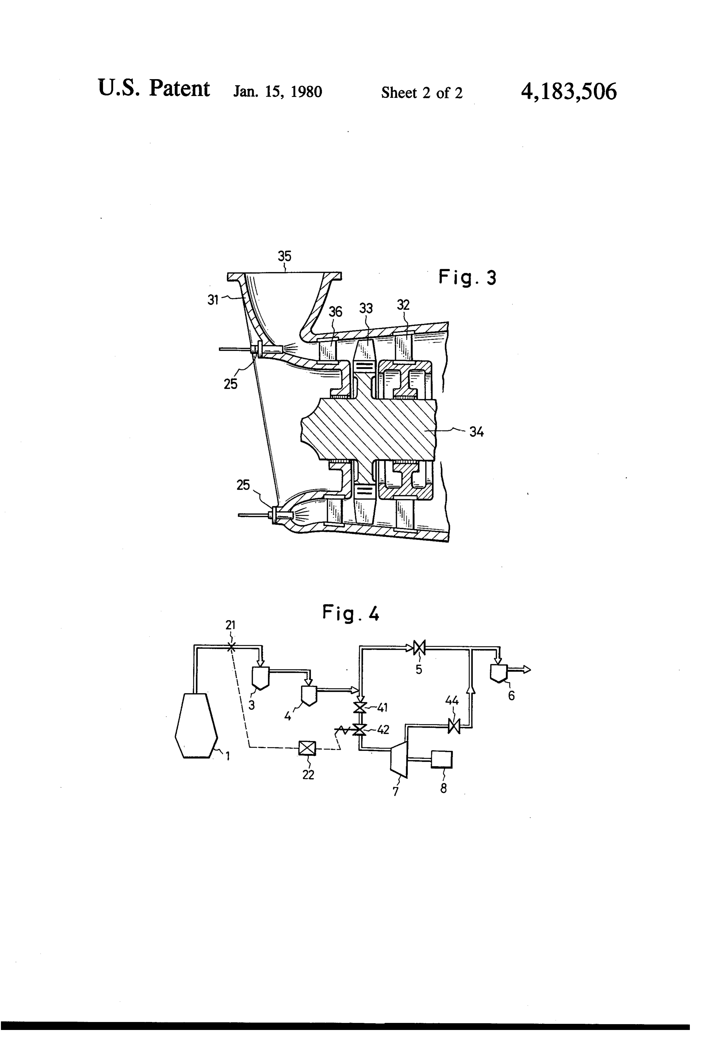
The drawings illustrate embodiments of the present an exhaust gas discharged from the blast furnace 1 is invention, in which: first introduced in the dust collector 3 where coarse FIG. 1 is a diagram illustrating means for actuating an dust particles are precipitated and separated. Then, the emergency shut off valve on receipt of a signal indicat 65 gas flow is introduced into the venturi scrubber 4 where ing occurrence of the blow-out phenomenon to inter considerable proportions of fine dust particles are re cept the flow of an exhaust gas into a turbine; moved by spraying of water or a chemical solution and FIG. 2 is a diagram illustrating means for spraying the temperature of the gas is lowered to such a level that cooling water into a turbine on receipt of a signal indi the gas can be used in the turbine, namely 60' to 80° C.
Page 6scan →
The flow rate of the gas passing through the gas flow casing 31. A cooling water spraying, nozzle 25 is control passage 2d is controlled by the septum valve 5 mounted in the vicinity of a gas supply opening 35 so so that the pressure of the blast furnace pressure is main that cooling water is sprayed to a first stage stationary tained at a certain level irrespectively of the load on the blade 36 fixed to the casing 31. Cooling water sprayed turbine 7. The exhaust gas from the turbine 7 joins the from the nozzle 35 is dispersed in the gas flowing in the gas flow from the passage 2d, and the combined gas is casing 31 and receives heat therefrom and evaporates, fed to a subsequent gas-utilizing plant through the sec whereby the temperature of the gas is lowered to a ond venturi secubber 6 and an exhaust gas flow passage predetermined level.
It is most preferred that the cooling water spraying
The temperature or pressure relay 21 is disposed to 10 nozzle 25 be disposed at a part for feeding the exhaust detect an abrupt change of the temperature or pressure gas to the turbine as shown in FIG. 3. If the temperature of the exhaust gas caused by the blow-out phenomenon of the gas is thus lowered by spraying of cooling water, in the blast furnace 1. It is preferred that the sensing part elevation of the temperature at the respective members of the relay 21 be composed of a material which is not of the turbine is reduced at a lowest level and degrada degraded even if always exposed to dust-containing 15 tion of a material poor in the heat resistance, for exam exhaust gas, and that the surface of the sensing part of ple, a coating layer formed on the stationary blade or the relay 21 be covered with a crystalline metal oxide the like to prevent adhesion of dusts, can be effectively ceramic coating and the coating surface be polished so prevented. Moreover, there can be attained an effect of as to prevent adherence and deposition of dusts. removing dusts adhering onto the stationary blades and The temperature or pressure relay 21 may be dis the inlet portion of the casing.
posed at any part of the pipe passage laid out between If it is intended only to lower the temperature of the the blast furnace 1 and the turbine 7. However, in order gas fed to the turbine to a predetermined level, the to assure a sufficient time from the point of detection of , cooling water spraying nozzle may be disposed at a a temperature or pressure change by the blow-out phe . . position other than the above-mentioned point. For nomenon to the point of arrival of an abnormally high 25 example, it may be disposed at any part of the exhaust temperature gas at the turbine 7 and provide a sufficient gas pipe passage laid out from the blast furnace to the spare time for actuation of the turbine-protective de turbine.
vice, it is preferred that the relay 21 be disposed at a part As a special embodiment of the present invention, as close to the blast furnace 1 as possible. there can be adopted a method in which the tempera In the foregoing embodiment, when the blow-out 30 ture of a part which readily undergoes thermal degrada phenomenon takes place in the blast furnace 1, abnor tion is locally lowered. For example, when the first mal elevation of the temperature or pressure is detected stage stationary blade is coated with a material which is by the relay 21 to close the emergency shut off valve 41 likely to undergo thermal degradation, cooling water is and open the septum valve 5, whereby introduction of sprayed to protect only the area of the coating. In this the gas into the turbine 7 is intercepted. Since the opera 35 embodiment, the amount of water to be sprayed can be tion time of the emergency shut off valve is much reduced, but in many cases the temperature of the gas shorter than that of the septum valve, there may arise a passing through the turbine is not so lowered. How fear of elevation of the pressure in the entire system. ever, thermal degradation of the part that is likely to However, since the volume of the entire system is large, undergo thermal degradation can be effectively pre in general, this elevation of the pressure is not signifi vented.
Cant. When the blow-out phenomenon takes place in the In the foregoing first embodiment (I), the turbine 7 is blast furnace, because of elevation of the temperature not operated when the blow-out phenomenon takes and pressure, the output of the turbine is increased. place and the above protective means is actuated. In Accordingly, when the capacity of the power generator contrast, in the embodiment (II) where cooling water is 45 is limited, it is necessary to adopt any means coping sprayed in the interior of the turbine and the embodi with this increase of the output of the turbine. It is ment (III) where cooling water is sprayed to the gas possible to cope with the elevation of the pressure by flow passage leading to the turbine, the turbine can be opening and closing the septum valve and governor operated continuously even if the blow-out phenome valve according to a customary control, but special non takes place. The embodiment (II) where cooling 50 arrangement should be made to cope with the increase water is sprayed in the interior of the turbine is now of the output of the turbine caused by the rising of the described by reference to FIGS. 2 and 3. temperature. In the present invention, a temperature FIG. 2 is a systematic diagram similar to FIG. 1. In relay 21 is disposed as shown in FIG. 4, and a control FIG. 2, the turbine is provided with a water spraying circuit 22 is arranged so that when the temperature device, and reference numerals 23 and 24 represent a 55 detected by the relay 21 exceeds a predetermined lelvel, water pouring valve and a cooling water pipe, respec the governor valve is closed to a degree corresponding tively. When occurrence of the blow-out phenomenon to the excess of the temperature over the predetermined is detected by the pressure or temperature relay 21, the level. By this arrangement, it is made possible to pre water pouring valve 23 is opened on receipt of a detec vent an excessive load from being imposed on the tion signal, to sprinkle cooling water in the interior of 60 power generator.
the turbine and lower the gas temperature instanta In the embodiment (III), the water spraying means is neously to a predetermined level. located in the pipe passage upstream of the turbine. This FIG. 3 is a sectional view showing the main part of embodiment (III) is advantageous over the embodiment the embodiment where cooling water is sprayed into (II) in the point that disposition of water spraying means the turbine 7. Referring to FIG. 3, a rotor boss 34 is 65 is facilitated, a plurality of water spraying nozzles may rotatably supported at the center of a casing 31 and a be mounted and maintenance of the water spraying moving blade 33 is fixed to the periphery of the rotor means can be done with ease. At any rate, in both the boss 34. Further, a stationary blade 32 is mounted on the embodiments (II) and (III), in order to facilitate lower 7 coated with material preventing adhesion of dust, said ing of the gas temperature, it is necessary to atomize the water spray. material readily undergoing thermal distortion or deg What is claimed is: radation, a system for protecting said thermally distort 1. In connection with a blast furnace of the type sub able or degradable material from damage due to said ject to a blow-out phenomenon, a protective device for 5 blow-out phenomenon in said blast furnace comprising a turbine adapted to be driven by exhaust gas generated detecting means for sensing and detecting the occur in said blast furnace, said protective device comprising rence of said blow-out phenomenon in said blast furnace spraying means for spraying cooling water to a gas and spraying means activated in response to said detect transportation passage between said blast furnace and ing means sensing the occurrence of said blow-out phe said turbine, and detection means for sensing the blow O nomenon for spraying water on said thermally distort out phenomenon in said blast furnace, said spraying able or degradable material in said turbine. means being activated on receipt of a signal from said 7. In connection with a blast furnace of the type sub detecting means. ject to a blow-out phenomenon, a protective device for 2. A protective device as set forth in claim 1 wherein a turbine driven by exhaust gas generated in said blast the cooling water-spraying position is the gas inlet por 15 furnace, said protective device comprising spraying tion of the turbine. means for spraying cooling water to the interior of said 3. A protective device as set forth in claim 1 wherein turbine, and detection means for sensing said blow-out said detection means capable of sensing and detecting phenomenon in said blast furnace, said spraying means occurrence of the blow-out phenomenon in the blast being activated on receipt of a signal from said detect furnace is means sensing the change of the temperature 20 ing means.
and/or pressure of the exhaust gas. 8. A protective device as set forth in claim 7 wherein 4. A protective device as set forth in claim 1 wherein said detection means capable of sensing and detecting a stationary blade of the turbine is coated with a mate occurrence of the blow-out phenomenon in the blast rial which prevents adherence of dust and cooling furnace is means sensing the change of the temperature water is sprayed to the vicinity of a gas feed inlet of the 25 and/or pressure of the exhaust gas. turbine. 9. A protective device as set forth in claim 7 wherein 5. A protective device as set forth in claim 1 wherein a stationary blade of the turbine is coated with a mate a passage for the exhaust gas from the blast furnace is rial which prevents adherence of dust, and cooling branched into a part for feeding the exhaust gas to the water is sprayed to the vicinity of a gas feed inlet of the turbine and a part for controlling the flow of the exhaust turbine.
gas so that a predetermined amount of the exhaust gas is 10. A protective device as set forth in claim 7 wherein supplied to the turbine. a passage for the exhaust gas from the blast furnace is 6. In connection with a blast furnace of the type sub branched into a part for feeding the exhaust gas to the ject to a blow-out phenomenon, an apparatus adapted turbine and a part for controlling the flow of the exhaust for feeding an exhaust gas generated in said blast fur 35 gas so that a predetermined amount of the exhaust gas is nace to a turbine and driving said turbine by the action supplied to the turbine.
of said exhaust gas, said turbine including portions
Provenance
- Collection
- Patents citing this work
- Pages
- 7
- Method
- pdftotext (the PDF's own text layer) + pdftoppm 300dpi page scans
- Patent office record
- patents.google.com →
- Source
- Google Patents citing-documents table
- Assignee
- Mitsui Engineering & Shipbuilding Co., Ltd.
- Published
- 1980-01-15
- Transcribed from
- patentimages.storage.googleapis.com →