

patent · US4190023A
Cooling system for liquid-cooled type of two-cycle multicylinder engine
26 February 1980
Text
Page 1bibliographic recordscan →
United States Patent (19)
Fujikawa et al.
54 COOLING SYSTEM FOR LIQUID-COOLED
TYPE OF TWO-CYCLE MULTICYLNDER
ENGINE
(75) Inventors: Tetsuzo Fujikawa; Michio Nishimura, both of Kobe, Japan (73) Assignee: Kawasaki Jukogyo Kabushiki Kaisha, Hyogo, Japan
Related U.S. Application Data
doned.
51 Int. Cl. ................................................ FO2F 1/14 (52) U.S. C. .............................. 123/41.72; 123/41.74;
3,616,779 1 1/1971 Newkirk ............................. 23/4.86 3,911,876. 10/1975 Freyn ................................ 123/4.86 Primary Examiner-Ira S. Lazarus
Assistant Examiner-Jeffrey L. Yates
Attorney, Agent, or Firm-Toren, McGeady and Stanger
A cooling system adapted for a liquid-cooled type of two-cycle multicylinder engine. The thick-walled por tion of a crank case between adjacent cylinders is pro vided with a cooling-liquid passage. The delivery port of a liquid pump is fixedly secured to one end of the cooling-water passage at the intake side of the cylinder, while the other end of the passge at the exhaust side of the cylinders is flow connected to liquid jackets in the cylinder blocks.
Claim, 2 Drawing Figures
Drawings
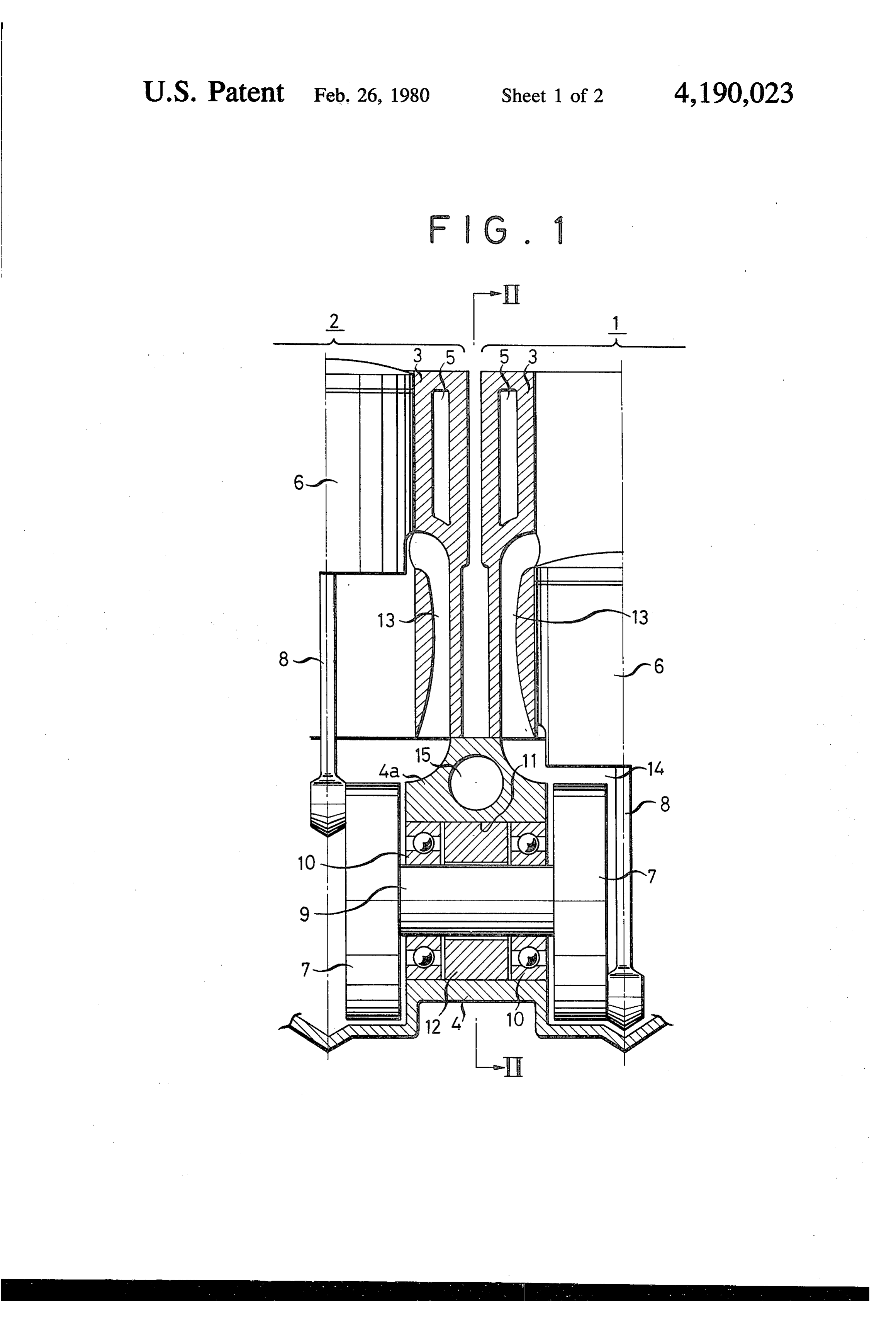
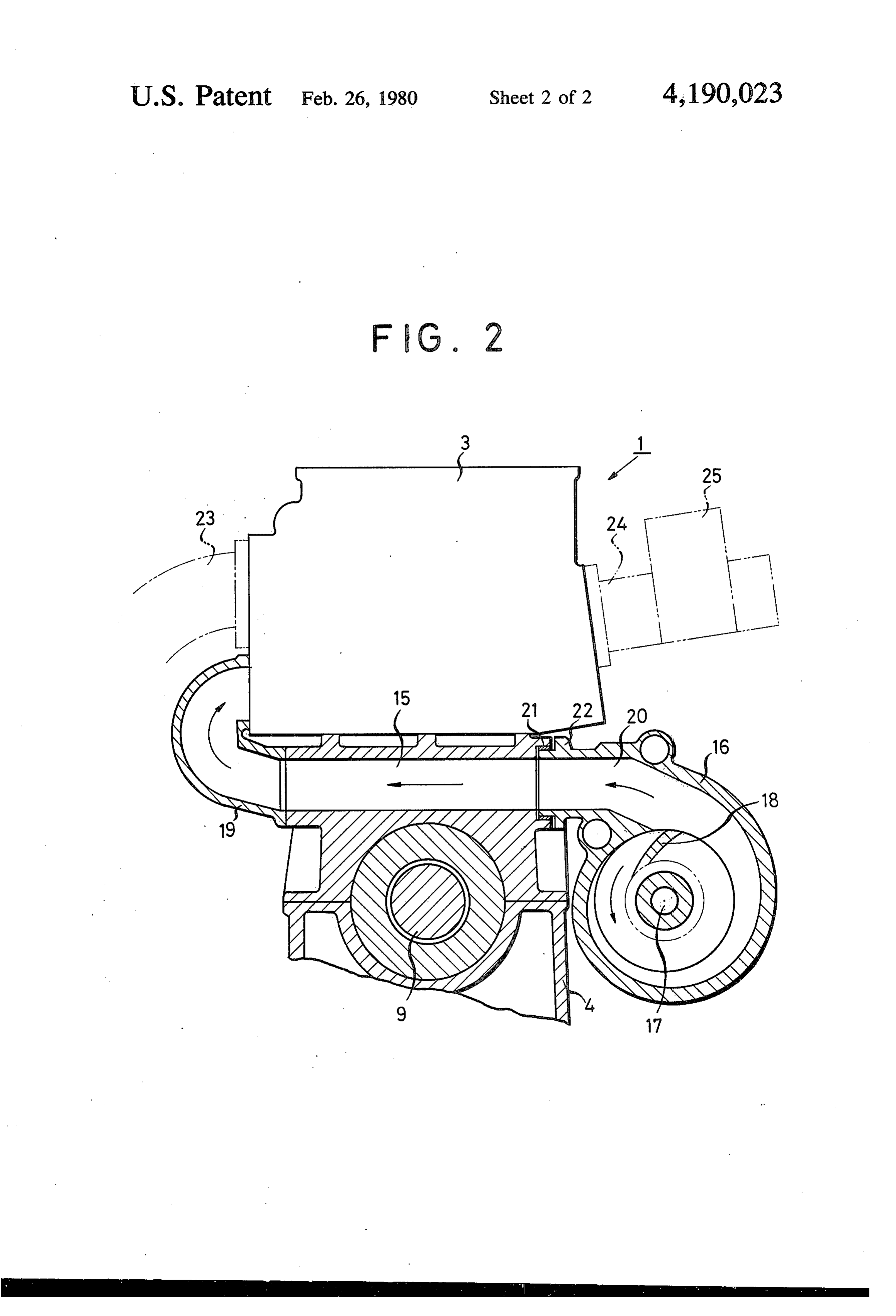
FIG. 2 is a sectional view taken along the line II-II 60 In this way, the cooling system according to the of FIG. . invention is of such construction that the generally DETAILED DESCRIPTION thick-walled portion 4a of the crank case between adja cent cylinders is provided with the cooling-liquid pas
Page 2drawing sheetscan →
Page 3drawing sheetscan →
Page 4scan →
other. Alternatively, cylinder blocks 3, 3 may be inte
COOLING SYSTEM FOR LIQUID-COOLED TYPE grally formed. Each of the cylinder blocks 3, 3 is
OF TWO-CYCLE MULTICYLENDER ENGINE formed with a liquid jacket 5, and pistons 6, 6 within the cylinder blocks 3, 3 are each pivotally connected to a
This is a continuation of application Ser. No. 688,027, 5 crank web or counterweight 7 through a connecting filed May 19, 1976, now abandoned. rod 8. The jackets are filled with a cooling liquid such BACKGROUND OF THE INVENTION as water, an anti-freeze solution or similar liquid. The crank webs 7, 7 are firmly fixed to ends of a crankshaft
This invention relates to a cooling system for a liquid 9 and the liquid jacket or cooling passage 5 is located in cooled type of two-cycle multicylinder engine. 10 proximity to the crankshaft 9 and approximately mid There are certain prior art cooling systems in which way between the crank webs 7, 7. The crank shaft 9 is the delivery port of a water pump mounted on one end rotatably supported by means of bearings 10, 10 of a crank shaft is flow connected to a water passage mounted in a bearing bore 11 of the crank case 4. The within a crank case, which is further flow connected reference numeral 12 indicates a labyrinth seal and 13, directly to a water jacket within a cylinder block for 15 13 scavenging passages perforated in the cylinder eliminating any piping arrangement. However, such blocks 3, 3. In case of the integrally formed cylinder conventional cooling systems require an increase in blocks 3, 3, the jackets 5,5 may communicate with each wall thickness of a portion of the crank case to provide other in the blocks 3, 3.
therein the water passage in the axial direction of the Hereupon, it is to be noted that in a water-cooled type crank shaft, and hence had a disadvantage that the 20 of two-cycle multicylinder engine, there is originally a crank case becomes greater in size. Furthermore, the greater space in the crank case between adjacent cylin water pump mounted on the end of the crank shaft ders, and in view of such respect the present invention increased disadvantageously the overall length of the contemplates to utilize effectively such space. That is, a engine in the axial direction of the crank shaft. portion 4a of the crank case 4 enclosed by the scaveng The prior art to which the invention is directed also 25 ing passages 13, 13 at both sides and the bearing bore 11 includes another type of cooling systems in which cool is generally formed thickly. This is because firstly the ing hoses are used for piping. Such cooling systems volume of a crank chamber 14 is made less in order to require longer and complicated piping because of a increase the compression ratio in the crank chamber and number of hoses extending along the outside of an en secondly there is a limit to decrease in the distance gine, which resulted in increase in the number of parts 30 between adjacent cylinders because of the liquid jackets and higher cost for manufacturing. 5, 5 provided in the wall of cylinder blocks 3, 3. There BRIEF SUMMARY OF THE INVENTION fore, according to the invention, a cooling-liquid pas sage 15 having a relatively great diameter is perforated
Accordingly, it is an object of the present invention in the thick-walled portion 4a between the adjacent to provide a cooling system for a liquid-cooled type of 35 cylinders at right angles to the axis of the crank shaft 9. two-cycle multicylinder engine in which the above Now referring to FIG. 2 showing a section taken mentioned disadvantages are eliminated, the space be along the line II-II of FIG. 1, the reference numeral 16 tween adjacent cylinders is utilized effectively and the indicates a liquid pump, 17 a pump shaft, 18 an impeller distance for piping is decreased. mounted on the pump shaft 18, and 19 a pipe such as It is another object of the invention to provide a 40 bend pipe, branch pipe or the like. The cooling-liquid cooling system for a crank case compression type of passage 15 is flow connected to the jackets 5, 5 in the two-cycle engine which permits an increase in delivery cylinder blocks 3, 3 by the pipe 19. A delivery port 20 ratio. of the water pump 16 is fitted in the end portion of the According to the present invention, there is provided liquid-cooling passage 15 at the intake side of the cylin a cooling system comprising a cooling-liquid passage 45 ders through a O-ring 21 and fastened at its flange por formed in a thick-walled portion of a crank case be tion 22 to the crank case 4 by means of bolts (not tween adjacent cylinders, a liquid pump having a deliv shown). The shaft 17 of the water pump 16 is connected ery port fixedly secured to one end of said cooling-liq to the crankshaft 9 through a power transmission means uid passage at the suction side of the cylinder and means such as gears, chain, belt or the like and adapted to be for flow connecting the other end of the cooling-liquid 50 rotated in the arrow-marked direction. passage at the exhaust side of the cylinders to water In operation, upon rotation of the impeller 18, pres jackets in the cylinders. sure is applied to a cooling-liquid within a suction port These and other objects, features and advantages of (not shown) which communicates with a radiator (not the invention will become more apparent upon a read shown), and the cooling-liquid is introduced into the ing of the following detailed specification and drawings, 55 liquid jackets at the exhaust side in the first and second in which: cylinders 1 and 2 through the delivery port 20, cooling FIG. 1 is a vertical sectional view taken on the center liquid passage 15 and the pipe 19. The other numeral 23 of a crank shaft of an engine illustrating an embodiment indicates an exhaust manifold, 24 a suction manifold and of the present invention; and 25 a carburetor.
FIG. 2 is a sectional view taken along the line II-II 60 In this way, the cooling system according to the of FIG. . invention is of such construction that the generally DETAILED DESCRIPTION thick-walled portion 4a of the crank case between adja cent cylinders is provided with the cooling-liquid pas
Referring to FIG. 1, the reference numerals 1 and 2 sage 15 at right angles to the axis of the crank shaft 9, indicate a first cylinder and a second cylinder, respec- 65 and the delivery port 20 of the water pump is flow tively. These cylinders 1 and 2 are constituted by cylin connected to the end of the passage 15 at the suction der blocks 3, 3 and a crank case 4. The cylinder blocks side of the cylinder. With such construction, the liquid 3,3 and the crank case 4 are firmly connected with each pump 16 can be mounted on the crank case in a rela 5 tively wide space below the carburetor 25, whereby the piston means operatively associated with said cylinder distance for piping of the pipe 9 may be decreased and means, connecting rod means and crank web means there is no possibility of increasing the configuration of operatively interconnecting said piston means with said the crank case 4. Further, the provision of the cooling crankshaft, said crank web means including a pair of liquid passage 15 permits the crank case 4 to be cooled 5 crank webs located on opposite ends of said crankshaft, and, with a crank case compression type of two-cycle crankshaft bearing means located between said crank engine, also permits an increase in the delivery ratio so shaft and said thick-walled portion of the crankcase, that some increases in output may be expected. In addi and liquid jackets located in said cylinder block means, tion, the cooling system according to the invention is the improvement comprising:
simple in construction and easy to manufacture. 10 a cooling system for said engine consisting essentially Obviously, many modifications and variations of the of a cooling liquid passage formed to extend present invention are possible in the light of the above through said thick-walled portion of said crankcase teachings. For example, gaskets may be interposed in in a generally straight configuration from said first place of O-ring 21 between the delivery port 20 and side to said second side of said pair of cylinders at crank case 4, and between the pipe 19 and crank case 4. 15 a location generally equivalently spaced from each Further, the end of the cooling-liquid passage 15 at the of said adjacent cylinders; exhaust side of the cylinders may be flow connected said cooling liquid passage being located in an area directly to the liquid jackets in the cylinder blocks 3,3 generally above said crankshaft and being in the through a passage traversing the joint surfaces of the form of a throughhole formed through said thick cylinder blocks 3, 3 and crank case 4 to thereby elimi- 20 walled portion of the crankcase and located in nate the pipe 19. In the drawing, the cooling-liquid proximity to said crankshaft bearing means at a passage 15 is provided between the crank shaft 7 and point approximately equidistantly spaced from said cylinder blocks 3 between the adjacent cylinders, but it pair of crank webs;
may be provided below the crank shaft 7. a liquid pump having a delivery port connected in What we claim is: 25 flow communication to one end of said coupling 1. In a two-cycle multicylinder engine including cyl liquid passage at said first side of said pair of cylin inder block means defining at least a pair of cylinders ders located adjacent each other, said pair of cylinders defin said liquid pump being mounted beneath said carbure ing a first side and a second side opposite thereto, carbu tor means and attached to said crankcase at said retor means including fuel intake means for said pair of 30 first side of said pair of cylinders; and cylinders located on said first side of said pair of cylin means on said second side of said pair of cylinders ders, exhaust means located on said second side of said flow-connecting the other end of said cooling liq pair of cylinders, a crankcase including a thick-walled uid passage to said liquid jacket in said cylinder portion thereof located in an area generally between block means at a location adjacent said exhaust said adjacent cylinders, a crankshaft approximately 35 eaS.
equidistantly spaced between said first and second sides,
Provenance
- Collection
- Patents citing this work
- Pages
- 5
- Method
- pdftotext (the PDF's own text layer) + pdftoppm 300dpi page scans
- Patent office record
- patents.google.com →
- Source
- Google Patents citing-documents table
- Assignee
- Kawasaki Jukogyo Kabushiki Kaisha
- Published
- 1980-02-26
- Transcribed from
- patentimages.storage.googleapis.com →