

patent · US4197715A
Heat pump
15 April 1980
Text
Page 1bibliographic recordscan →
United States Patent (19) 11 4,197,715 Fawcett et al. (45) Apr. 15, 1980 54. HEAT PUMP Attorney, Agent, or Firm-Thomas H. Murray; Clifford A. Poff Inventors: Sherwood L. Fawcett, Columbus;
James N. Anno, Cincinnati, both of (57) ABSTRACT
Ohio Heat pump apparatus employing a continuous loop Assignee: Battelle Development Corporation, passageway containing a plurality of freely-movable, unrestrained bodies. The bodies are accelerated around
Columbus, Ohio the passageway in one direction by adiabatic expansion *) Notice: The portion of the term of this patent of a fluid between the bodies in an expander region of subsequent to Oct. 3, 1995, has been the passageway. The expanded, cooler fluid is dis disclaimed. charged from the passageway via one or more vent intake ports in the passageway beyond the expander 21 Appl. No.: 918,234 region. Warmer fluid enters the passageway via said ports and is compressed between the propelled bodies in 22 Filed: Jun. 23, 1978 a compression region of the passageway, thereby rais ing its temperature from a first temperature (e.g., the
Related U.S. Application Data temperature of the outdoor atmosphere or an industrial 63 Continuation-in-part of Ser. No. 812,559, Jul. 5, 1977, waste heat stream) to a second temperature higher than Pat. No. 4,117,696. the first. The compressed, warmer fluid is thereafter passed through a heat exchanger to extract heat. In Int. Cl. .......................... F25B 1/00; F25B 13/00 passing through the compression region the bodies are 52 U.S. Cl. ........................................ 62/115; 62/324; decelerated and they then pass through a thruster re 60/325; 418/33; 62/467 R gion of the passageway wherein a force is applied to the Field of Search ..................... 62/115,324 B, 325, bodies to counterbalance the external forces acting 62/401, 402, 116,467; 60/325; 418/33; 290/1 R against the bodies as they move around the loop pas
sageway. From the thruster region the bodies pass to the expander region to repeat the cycle. From the heat
3,859,789 1/1975 Fawcett et al. ........................ 60/325 compressed fluid from an external source, is introduced 3,927,329 12/1975 Fawcett et al......................... 418/33 into the expander region to again accelerate the bodies. Primary Examiner-Lloyd L. King 34 Claims, 7 Drawing Figures
admi
OOOAS) A/A /W
Drawings
Page 2drawing sheetscan →
Page 3drawing sheetscan →
Page 4drawing sheetscan →
Page 5drawing sheetscan →
Page 6scan →
ports is a compression region in the passageway
HEAT PUMP wherein the fluid is compressed between successive ones of the propelled bodies. In this region, energy
CROSS-REFERENCE TO RELATED transfer takes place in which process the kinetic energy APPLICATION of the bodies is used to adiabatically compress the fluid. This application is a continuation-in-part of applica The compressed fluid is removed from the passageway tion Ser. No. 812,559, filed July 5, 1977, now U.S. Pat. and passed through an optional, but preferred, check No. 4,117,696. valve and then through heat exchanger means con
Background of the invention
nected to the passageway at the end of the compression 10 region for extracting heat from the fluid thus com
As is known, the usual heat pump used to heat build pressed. An optional, but preferred, latch extends into ings, for example, includes an electrically-driven com the passageway at the end of the compression region to pressor, a throttling valve, an evaporator located in the prevent backward motion of the bodies. The cooled ambient atmosphere outside the building, and a con 15 compression fluid is reintroduced into the passageway denser within the building which discharges heat as a together with an additional charge of compressed fluid refrigerant is condensed. Such systems are relatively from the external compressor to repeat the cycle. complicated, have low coefficients of performance The above and other objects and features of the in based upon actual thermal conversion and, of course, vention will become apparent from the following de require a liquid refrigerant which tends to be expensive tailed description taken in connection with the accom and may have toxic properties. Furthermore, the en 20 panying drawings which form a part of this specifica ergy input into the system is usually electrical and, tion, and in which:
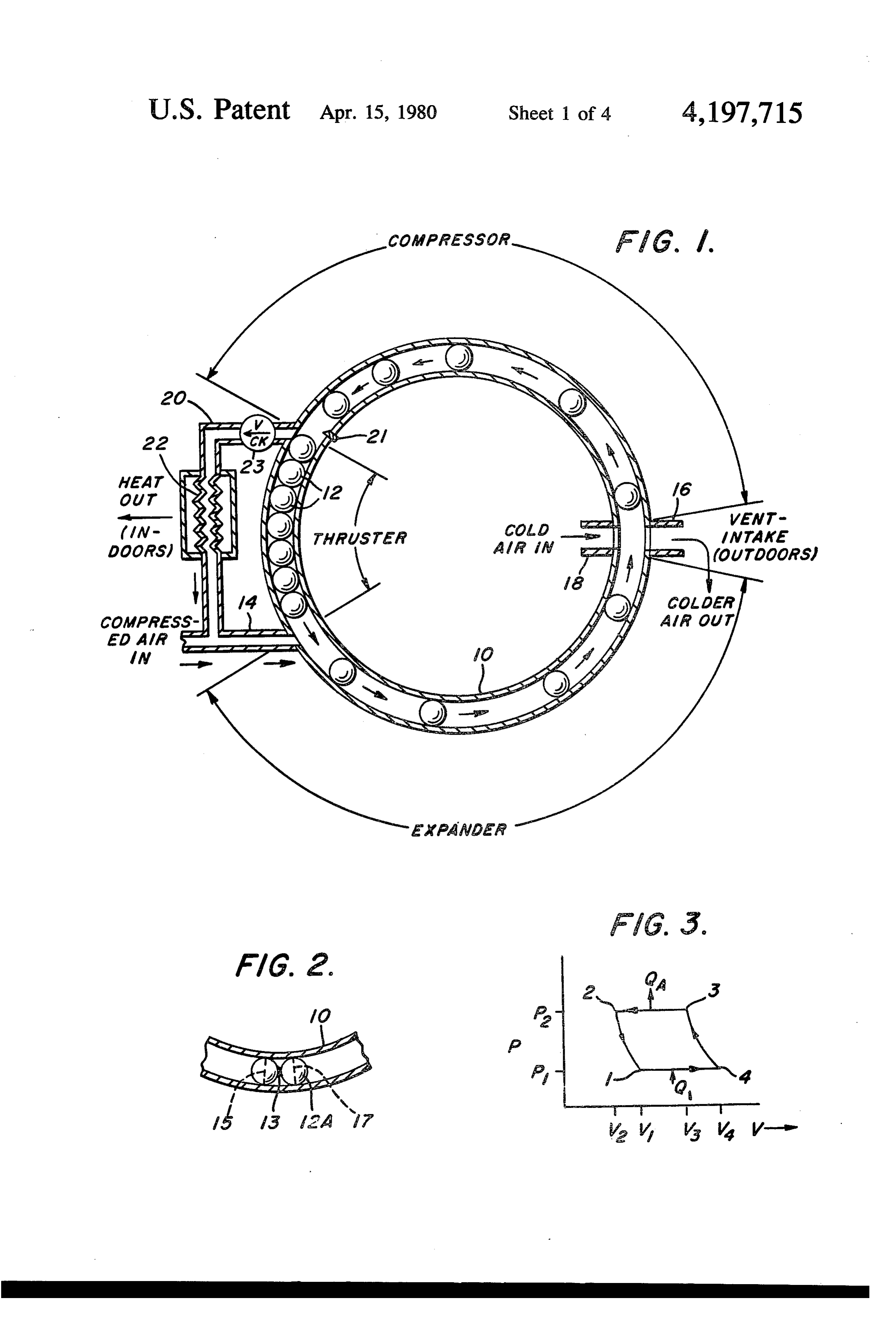
hence, does not utilize the heat rejected in the electrical FIG. 1 is a simplified schematic diagram of the unidi energy production. rectional energy converter heat pump of the invention; SUMMARY OF THE INVENTION 25 FIG. 2 is an illustration of an alternative form of In accordance with the present invention, a heat of unrestrained bodies which can be used in the heat pump pump is provided which can be used with a heat source the invention;
(such as natural gas, oil or coal), or a motor-driven cycle of3the
FIG. is a P-V diagram showing the thermodynamic apparatus of FIG. 1;
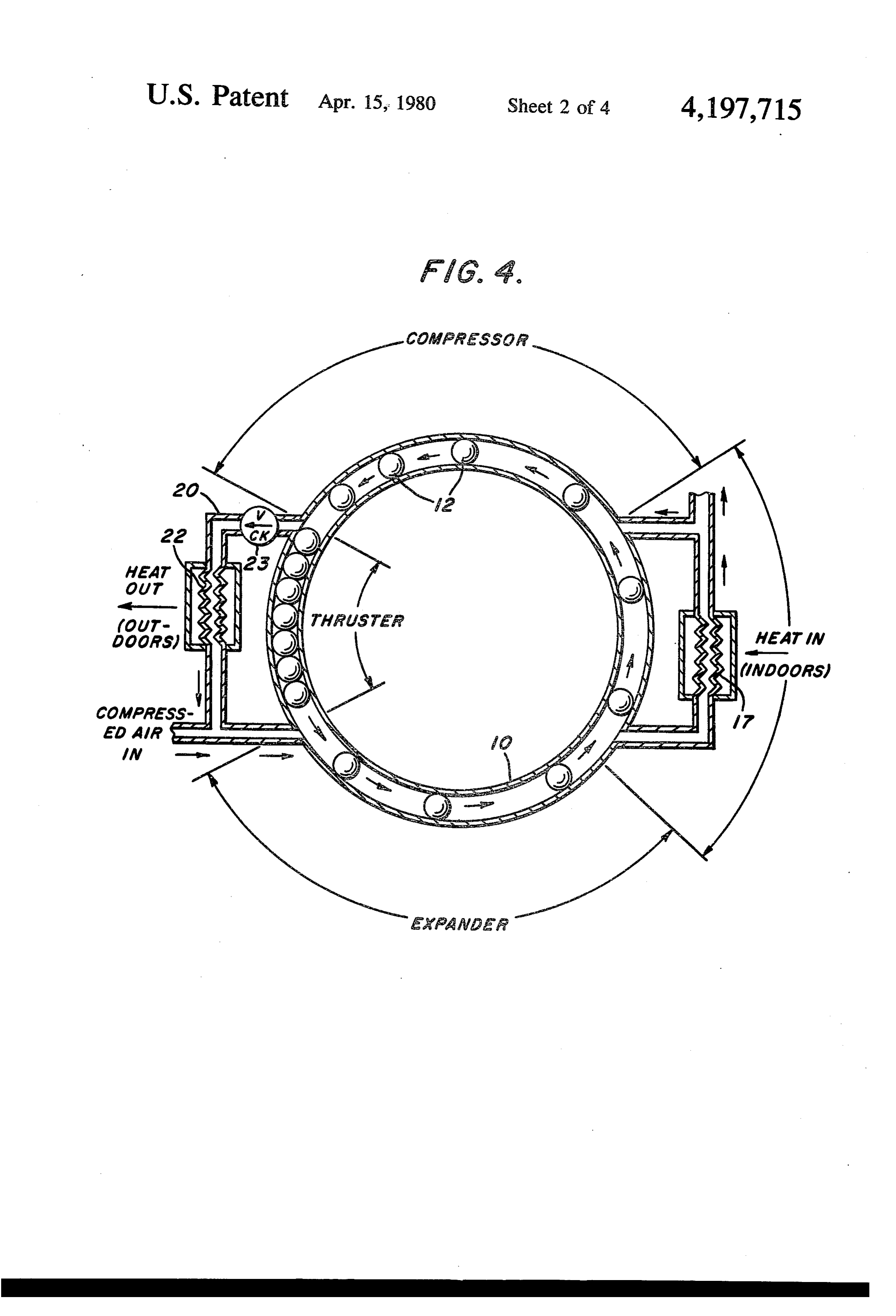
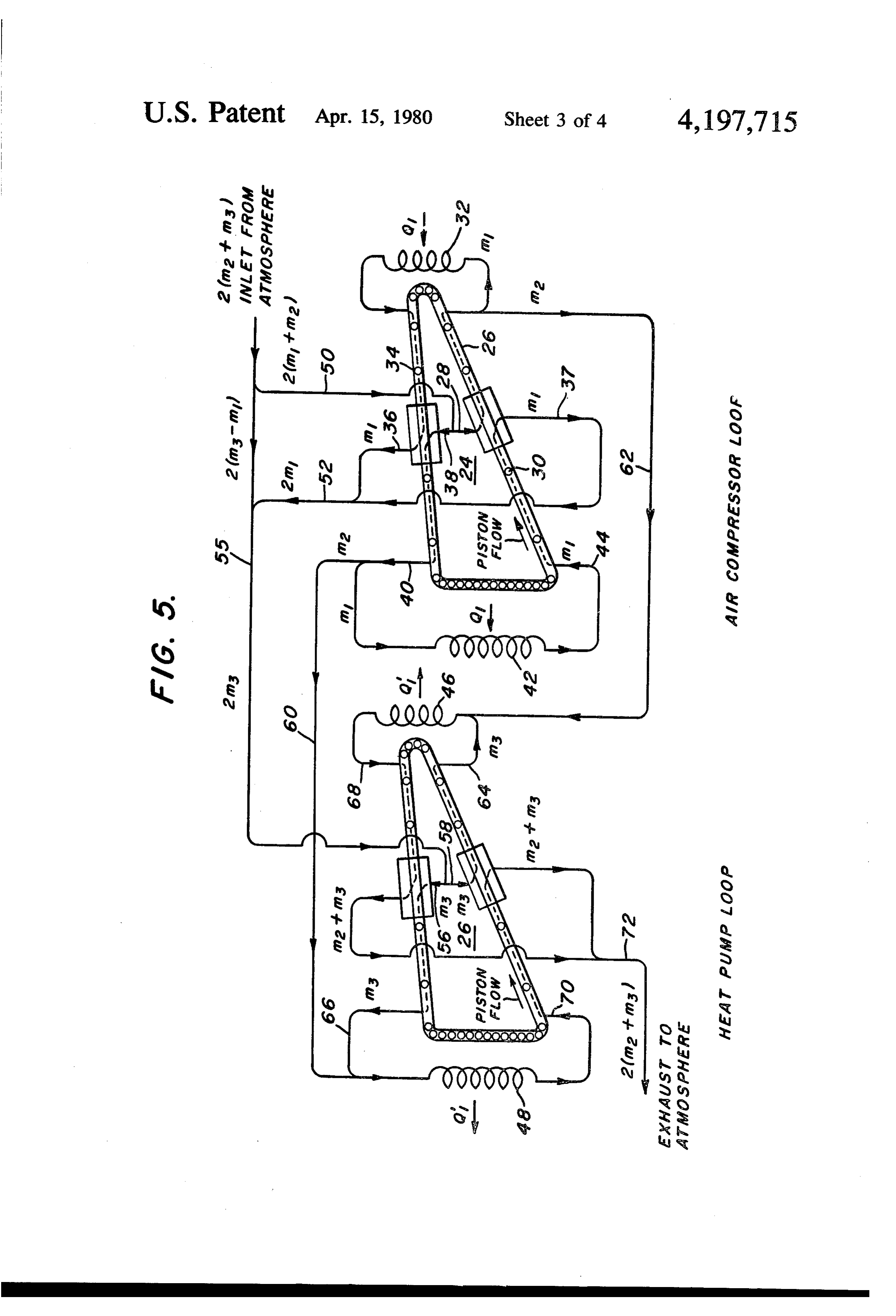
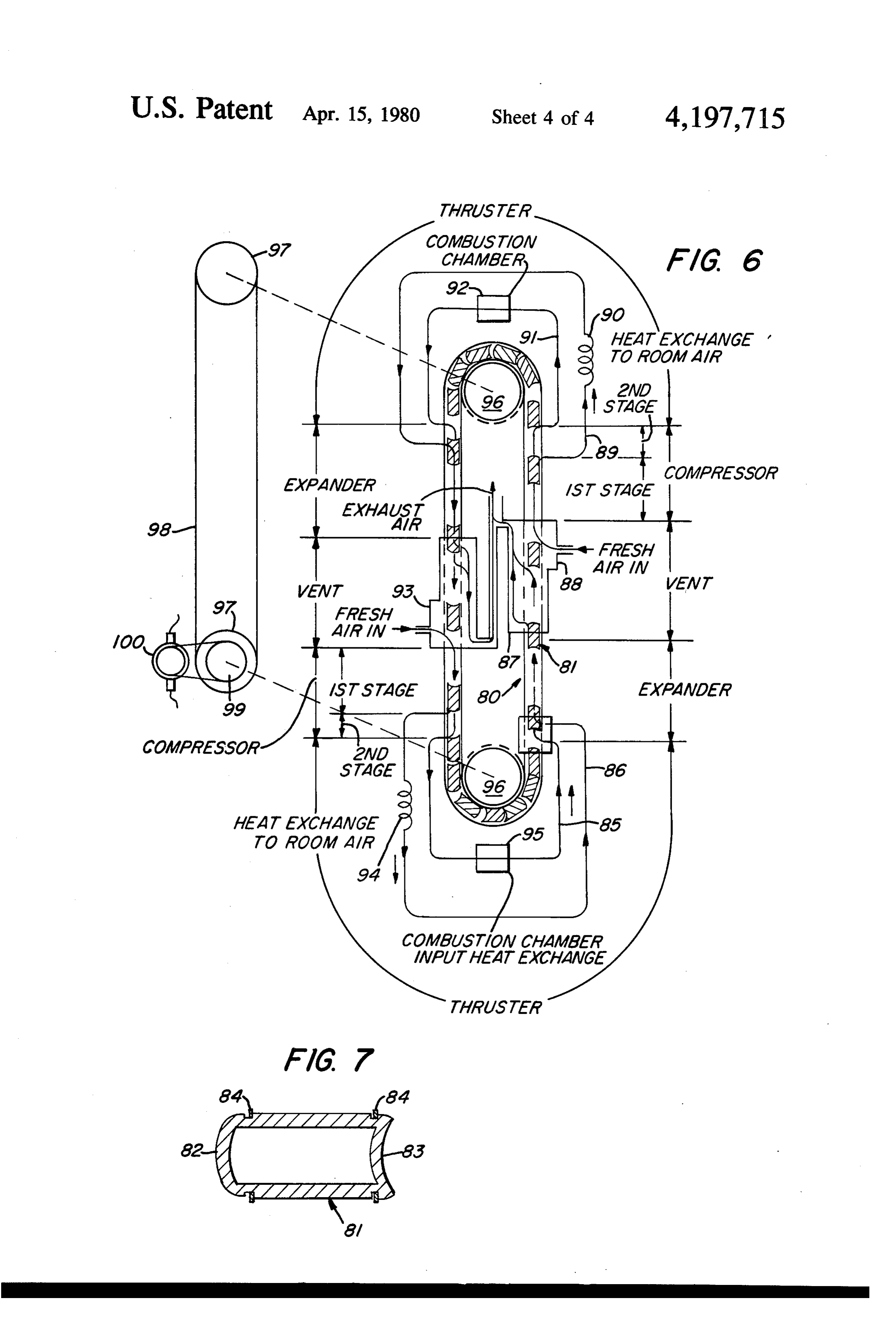
compressor and which can operate on simple fluids FIG. 4 is a simplified schematic diagram of the unidi such as air in contrast to the more expensive and toxic rectional energy converter heat pump of the invention refrigerants used in conventional prior art heat pumps. shown in a cooling (i.e., air conditioning) mode; At the same time, the heat pump of the invention is of FIG. 5 is an illustration of an embodiment of the relatively simple construction and has a high coefficient of performance. invention employing two double unidirectional energy The invention is based on certain of the principles set 35 converter devices, one of which is used as an air com forth in Fawcett et al U.S. Pat. No. 3,859,789 directed pressor and the other of which is used as a heat pump; to a unidirectional energy converter wherein bodies FIG. 6 is a simplified schematic diagram of unidirec movable around a continuous loop passageway are tional energy converter devices forming a compound utilized to convert one form of energy to another form heat engine and heat pump according to a further em of energy. In contrast to the apparatus shown in U.S. 40 bodiment of the present invention; and Pat. No. 3,859,789, however, the purpose of the present FIG. 7 is an illustration of a further form of an unre invention is to increase the heat content, and therefore, strained body which is particularly useful in the em the temperature, of a fluid such as air at one location bodiment of the invention shown in FIG. 6. and decrease it at another. That is, the apparatus is used With reference now to the drawings, and particularly to move or "pump' heat from a reservoir at a colder 45 to FIG. 1, the apparatus shown includes a closed-loop temperature (for example, the outdoor air or a waste passageway 10 defined by a housing having walls which heat stream) to a reservoir at a warmer temperature (for are preferably smooth and formed from metal. Disposed example, the indoor air or a process heat stream). When within the passageway 10 is a plurality of pistons 12, used for cooling purposes, the reservoirs are simply shown in the embodiment of FIG. 1 as solid spheroids. reversed with the heat pump taking heat from the 50 The tolerances or clearances between the surfaces of cooler indoors and exhausting it to the warmer out the spheroids and the inside walls of the passageway 10 doors as in a conventional air-conditioning system. are such as to permit the spheroids to move freely along Specifically, in accordance with the invention, there the passageway 10. However, fluid flow past the spher is provided a continuous loop passageway containing a oids within the passageway is substantially prevented. . plurality of freely-movable, unrestrained bodies. A 55 In the embodiment shown in FIG. 1, for example, the source of compressible fluid (e.g., air or a liquefiable loop passageway 10 has a circular cross section, but vapor such as Freon, etc.) under pressure is provided with other shaped bodies, other cross sections may be for generating a force to accelerate successive ones of utilized including elliptical or polygonal cross sections. the bodies in one direction around the passageway. In some cases, it is advantageous to weld two spheroids Energy transfer takes place in which process adiabatic 60 together as shown in FIG. 2. The body 12A, comprising expansion of the fluid is used to impart kinetic energy to two spheroids welded at 13, now has two circumferen the bodies. In a region in the passageway beyond the tial lines of contact 15 and 17 with the inside walls of the region in which fluid expansion takes place (i.e., the passageway 10. This arrangement does not impede the expander region), ports are provided to permit the ex movement of the body, but increases the sealing effect haust of the very cool working fluid and entrance of a 65 between the body and the interior wall. At the same warmer charge of fluid such as outdoor air. In a closed time, it decreases the chances of having the spheroids system (e.g., Freon, etc. fluid), these ports are simply pit the interior wall surface of the passageway in those connected to an in-line heat exchanger. Following these embodiments of the invention where a sharp bend oc 7 curs in the passageway and, further, reduces clearance between successive spheroids. Thus, heat is absorbed in problems due to deformations of the spheroids from this process from the cold reservoir (e.g., outdoor air). impacts. The actual volume between the spheroids remains es As shown in FIG. 1, the continuous loop passageway sentially constant during this operation, but the specific 10 is divided into sections. In an expander section, com volume increases to V4 between points 1 and 4 in FIG. pressed air from a suitable compressor, not shown, en 3. In other words, less mass of gas enters the loop ters the passageway 10 through conduit 14. This causes through port 18 in each unit cell than was exhausted successive ones of the bodies 12 to be propelled around from the unit cells via port 16. This difference in mass is the passageway 10 in a counterclockwise direction as made up by the additional air which enters the system viewed in FIG. 1. That is, the compressed air from 10 from the external compressor via conduit 14. conduit 14 along with compressed air from heat ex The fresh charge of gas is then compressed adiabati changer 22, as described below, enters the passageway cally between points 4 and 3 in FIG. 3 to volume V3 at 10 and expands adiabatically imparting kinetic energy in temperature T3 and pressure P2. The pressurized heated the form of increased forward velocity to each body 12 gas is then exhausted from the compressor section via while the gas between successive ones of the bodies is 15 conduit 20 through check valve 23, and heat is ex reduced in temperature. As the bodies pass port 16 tracted through the heat exchanger 22. The unit cell connected to the passageway 10, the cooler air which collapses and the cycle is then repeated, the total work has been adiabatically expanded exits to the atmosphere being represented by the area within the lines between and air from the ambient atmosphere enters the passage points 1, 2, 3 and 4 in FIG. 3.
way through port 18 and is thereafter compressed in a 20 The air-conditioning (i.e., cooling) mode of operation compression region of the passageway. If a liquefiable of the heat pump is shown in FIG. 4. The system is vapor, rather than air, is used, or if for any other reason essentially the same as that of FIG. 1 and, accordingly, it is desired to maintain a closed system, the ports may elements in FIG. 4 which correspond to those of FIG. be arranged and connected to conventional heat ex 1 are identified by like reference numerals. In this case, changer means (not shown) in any known manner. In a 25 port 16 corresponds to the cool air duct of an air-condi typical embodiment of the invention, a plurality of ports tioning system; whereas port 18 corresponds to the 16 and 18 is provided. The kinetic energy of the moving warm return. As an optional feature, heat exchanger bodies is used to compress the gas entering at port 18, means 17 may be connected to ports 16 and 18, necessi and the compressed gas exits from the passageway 10 tating a slight rearrangement of these ports as shown. through conduit 20 connected to one side of a heat 30 The heat exchanger 22, in an air-conditioning system, exchanger 22 via check valve 23. In the compression will be located external to the building which is being process, the temperature of the air is, of course, in cooled and would correspond to a conventional con creased as well as its heat content. Part of the heat is densing coil in a refrigeration system. The same basic extracted by means of the heat exchanger 22. The gas thermodynamic cycle shown in FIG. 3 is employed; which passes through the heat exchanger 22 is then 35 however cycles other than the Brayton refrigeration combined in conduit 14 with the compressed air from an cycle are also possible.
external source (not shown) to propel the bodies 12 in In the air-conditioning mode between points 2 and 1 the expander section. in FIG. 3, the expander region takes air from the out Another optional, but preferred, feature of the inven door heat exchanger 22 and adiabatically expands it to a tion comprises latch means 21 located at or near the end temperature lower than the indoor temperature. The of the compression region and adapted to prevent back cooler air is exhausted into the indoors through exit port ward motion of the bodies in this region after their 16; or it can be passed through an indoor heat ex kinetic energy has been reduced. Any conventional changer. Between points 1 and 4 of FIG. 3, the unit cell latch means may be used, such as, for example, a spring picks up a charge of warmer indoor air (Q). Between powered, beveled latch 21 (spring not shown) operating 45 points 4 and 3, this warmer air is adiabatically com in a manner similar to an ordinary door latch. That is, pressed to a higher pressure and temperature; and be the latch projects slightly into the passageway 10 and is tween points 2 and 3, the heat is exhausted to the out beveled in the direction of approach of the bodies so doors at constant pressure via the heat exchanger 22 that as each body comes into contact with the latch in a (Qld). The net work to drive the cycle is provided by counterclockwise direction it will depress the latch 50 make-up air from an air compressor, not shown, passing allowing it to pass, but the latch will not depress to into the expander section through conduit 14. The dif allow the bodies to retreat in a clockwise direction. ference between the cooling and heating modes is, of One possible thermodynamic cycle used in the heat course, that in the heating mode, heat is taken from pump of the invention is shown in FIG. 3 and is similar outdoors and pumped indoors; whereas in the cooling to a Brayton cycle. Between successive ones of the 55 mode, heat is taken from the indoors and pumped out bodies there is what can be termed a unit cell. Gas doors.
enters the expander section from conduit 14. The unit In FIG. 5, an embodiment of the invention is shown cell between successive bodies in the expander section wherein unidirectional energy converters are employed then seals off the inlet conduit 14 and adiabatically both as the heat pump and as the air compressor de expands between points 2 and 1 in FIG. 3 to a pressure 60 signed to supply compressed air to the heat pump. In P and volume V1 at temperature T. For simplicity, it FIG. 5, the air compressor loop is indicated generally will be assumed that the pressure P1 is atmospheric by the reference numeral 24 and the heat pump loop by pressure. The velocity of the lead body 12 is now v1, its the numeral 26. Each of the loop subsystems 24 and 26 maximum value. incorporates two unidirectional energy converters in The residual gas, whose temperature has been re 65 series.
duced to T1 in the adiabatic expansion, is then purged The air compressor loop 24 operates as follows. One through port 16 and ambient air at a higher temperature portion of atmospheric air (m1 +m2) enters the lower enters through port 18 and occupies the unit volume leg 26 of the loop at 28 via conduit 50 and then is com 8 pressed as the pistons or bodies 30 move upwardly in The thermodynamics of the expander and compres the leg 26. Part of the compressed gas exiting from the sor sections of the heat pump of the present invention top of the leg 26, m1, passes through a heat exchanger can be analyzed from ideal considerations as undergo 32 where heat is added from an external heat source Q1. ing isentropic processes. However, in actual operation, This source may, for example, comprise burning natural because of internal losses to the working fluid, the pro gas or any other suitable source of heat. The heated, cesses are not precisely isentropic. The processes take compressed gas is used in an upper leg 34 to propel the place, very nearly, as adiabatic processes, i.e., with no bodies 30 to the left by adiabatic expansion. After it has external heat losses, particularly when adequate and and been adiabatically expanded, and reduced in tem properly arranged insulation is attached to the outer peraure, in leg 34, the gas, m1, exits at 36; while a new 10 walls of the passageway forming the expander and com charge of atmospheric air (m1 +m2) enters at 38 where pressor sections. Thus, while isentropic operation might it is compressed by the propelled bodies 30 and exits at be assumed for the purpose of analysis, nevertheless the 40. Part of the compressed gas, m1, is passed through a actual operating processes of the heat pump are better heat exchanger 42 where heat is added, as described described as adiabatic.
above, the resulting compressed and heated gas being 15 In a similar fashion, the total external forces acting on reintroduced into the lower leg 26 at 44 where it adia the freely-movable bodies as they move around the loop batically expands to propel the bodies 30 to the right. must integrate to zero over time period for a particular After it has been adiabatically expanded, and reduced in body to completely transit the loop system under temperature, in leg 26, the gas, m1, exits at 37. The two 20 steady-state operation. This is simply in accordance portions (2m), comprising the adiabatically expanded with Newton's second law of motion. Since the mov gas, are then combined in conduit 52, with additional able bodies will encounter friction forces opposing the atmospheric air, 20m3-m), being added in conduit 55 direction of motion around the loop, these friction to yield a quantity of gas of 2m3. One-half of this quan forces must be counterbalanced by some external force tity, or m3, then enters the input 56 and the remaining 25 acting in the direction of motion. If the loop passage half, m3, enters input 58, the respective inputs of the two way around which the bodies travel is in a vertical, or compressor sections of the heat pump loop 26. near vertical, plane, such as shown, for example, in the it will be noted that the two individual portions m2 of embodiment of FIGS. 1 and 5, the force of gravity can the compressed and heated gas which exit from the air be used to provide at least part of the thrust to counter compressor loop 24 are passed through conduits 60 and 30 balance the friction forces. If the loop passagway must 62, respectively, to the heat exchangers 48 and 46, re be in a horizontal plane, alternative external thruster spectively, in the heat pump loop 26. In the heat pump forces may be applied to the bodies to counterbalance loop these two portions of gas m2 are individually com the frictional forces. For example, mechanically-pow bined with the two respective compressed gas portions ered devices such as cams, sprocket wheels, or worm m3 exiting from the two respective compressor sections 35 gears, or a linear magnetic motor may be used. at 66 and 64. The heat exchangers 46 and 48 can be of The number of bodies used in the heat pump of thi the finned-tube type through which air is blown by invention, the length of the various regions (i.e., expan means of a fan to heat the air within a building to a der and compressor) of the closed passageway and the temperature much higher than the atmospheric air ini total length of the closed-loop passageways are con tially entering the system, the heat emanating from the 40 stants for a particular heat pump design. This means that heat exchangers being indicated by the arrows Q' in the control system of the compressor and heat pump FIG. 5. The portion (m2 + m3) passing through the heat loops must regulate the operating parameters to main exchanger 46 is again introduced into the loop 26 at 68 tain approximately constant distribution of pistons to propel the bodies 30 by adiabatic expansion; and that around the loop for all operating levels. portion (m2 + m3) passing through heat exchanger 48 is 45 As will be appreciated, the invention has great flexi fed back into the loop at 70 to adiabatically expand and bility in design and performance in that it can be con propel the bodies forwardly in the lower leg of the loop structed in a continuum of sizes for heating or cooling 26. The two portions of adiabatically expanded gas, capability. Furthermore, it can be constructed as a mul 20m2 + m3), of reduced temperature are then exhausted tipleunit system in which various of the units can be through conduit 72 to the atmosphere; or can be passed 50 turned ON or OFF as the load requires. This also aids through an additional heat exchanger located within a reliability since if one of the units should fail, the system building when the system is used as an air-conditioning is still operable.
system. In the latter case, the heat exchangers 46 and 48 The system employs conduits, pistons or movable will, of course, be located outside the building. bodies, simple check valves, latches, and heat exchang As the fluid is compressed by the freely-movable 55 ers which should contribute greatly to reliability and bodies in the compressor sections, most of the kinetic economy for home heating and cooling systems pres energy of each body is transferred to increase the en ently utilized in natural gas or oil heating. thalpy of the gas and to remove the gas from the com It is also possible to use the invention in an arrange pressor section under increased pressure. Similarly, as ment in which the external compressor is replaced by a the fluid in the expander sections of the loop is adiabati 60 "pressurizer” which is an in-line component of the heat cally expanded between successive bodies in the expan pump loop system between the compressor and expan der sections, the enthalpy of gas is decreased and energy der regions. In this mode of operation, the apparatus is transferred to increase the kinetic energy of the bod would be designed to take in the same mass flow rate of ies. The energy transferred in the various processes gas as it exhaust in the vent-intake region, but conse around the loop, of course, must be conserved so that at 65 quently would compress to a lower pressure than re any time the total energy of a particular loop system is quired at the expander inlet. The role of the pressurizer, constant and the energy input and output is equal in then, is to pressure the gas sufficiently to make up this steady-state operation. difference using any known method for pressurizing.
Page 9scan →
The energy input to the pressurizer is the energy source exhaust manifold 87 forms an expander region of the for running the heat pump, as will be understood. passageway wherein energy of the hot compressed air In a typical installation, the overall length of the heat from conduits 85 and 86 is converted to kinetic energy pump loop shown in FIG. 5, for example, will be about of the pistons. The exhaust manifold coextends with the thirty-four times the diameter of the bodies 30; while 5 vent region wherein cold air is purged from each unit the overall length of the air compressor loop will be cell between the pistons in the passageway and replaced about twenty-seven times the diameter of the bodies 30. by fresh air fed through an entry port by a manifold 88 In FIG. 6, a further embodiment of the invention is from the outside. The manifolds 87 and 88 in the vent shown wherein serially-arranged unidirectional energy section terminate at the beginning portion of a compres converters form a compound heat engine and heat 10 sion region where the fresh air in the unit cell between pump. The heat engine uses a high pressure stage to pistons is compressed abiabatically by the kinetic en convert heat energy into net mechanical energy which ergy of the pistons.
is then converted in a low pressure stage of the heat The compression region has two stages in series. The pump to heat energy. More specifically, the unidirec largest portion and first of the compression stages ex tional energy converter according to the embodiment 15 tends to a discharge port for a conduit 89. The largest shown in FIG. 6 is comprised of two heat engines and portion of the air that is compressed between the pistons two heat pumps operating in parallel. A "racetrack' is passed from the unit cell through conduit 89 into heat shaped tubular passageway extends within a vertical exchanger 90 where the compressed air is cooled by plane to form a continuous loop passageway 80 contain heat exchange with room air. From the heat exchanger, ing a plurality of pistons 81. The pistons 81 may be 20 the cooled compressed air is reintroduced by conduit 89 spheroids or other desired configuration but preferably into the passageway through a port in the second expan the pistons take the form as shown in FIG. 7, of hol der region where the air is further cooled adiabatically lowed members having a cylindrical configuration with in a unit cell and exhausted to the atmosphere below sperical end surfaces. The leading end surface 82, in atmospheric temperature.
regard to the direction of travel by a piston, is convex; 25 Returning, now, to the compressor region, the sec whereas the trailing end 83 of the piston is concave. ond stage thereof utilizes the remaining kinetic energy Piston rings 84 are located in recesses formed within the of the pistons to further compress a small quantity of air outer cylindrical surface of the piston adjacent the con remaining in the unit cell. The second stage of the com vex cylindrical end 82 and the concave cylindrical end pressor region terminates at a port for a conduit 91 to 83. The hollow design of the pistons provides the neces- 30 deliver the compressed air from the second stage into a sary design mass and permits greater flexibility to the combustion chamber 92 where the compressed air is selection of material for the construction of the pistons heated and then fed by conduit 91 to reenter the pas independent of the mass required for design operation. sageway through a port at the entrance of the second The pistons rings, which are lightly loaded, reduce expander region. Unit cells of air are formed between losses to a minimum due to leakage of the fluid medium 35 the pistons after the pistons are passed through a around the pistons. Also, the use of rings places less thruster section wherein their direction of travel is al stringent manufacturing tolerances for the production tered, and thereafter the pistons pass downwardly along of the pistons. The pistons freely move within the pas the passageway. The downward path of travel by the sageway 80 and operate under light loads, particularly pistons is accompanied by the formation of unit cells as compared to the loads imposed on the pistons of an 40 therebetween while the pistons pass along a second internal combustion engine. The maximum velocity of expander region, second vent region and second com the pistons 81 is typically the same as the velocity of pression region that are essentially duplicates as far as pistons in an internal combustion engine. A thin film of function is concerned to the corresponding regions oil such as, for example, SAE 20 or molybdenum disul already described above. The unit cells formed between fide dry powder may be used, if desired, for lubrication 45 the pistons during their downward travel along the between the pistons and the raceway since the fluid passageway are supplied with heated compressed air temperature does not exceed 1500 F. and usually does from conduit 91 and supplied with further quantities of not exceed 1200 F. compressed air from conduit 89. As the leading piston As is shown in FIG. 6, the continuous loop passage of a unit cell passes from the expander section and en way 80 is divided into regions. In an expander region, 50 ters the vent section, the hot compressed air is expanded hot compressed air enters the passageway 80 through an adiabatically whereupon the heat energy of the air is entry port coupled to a conduit 85 whereby each piston converted to kinetic energy of the pistons. The lower, is accelerated, in succession, upwardly through the successively-arranged vent region includes a manifold lower right quadrant of the passageway. When a second 93 wherein cold air is purged from the unit cell between piston passes the entry port for conduit 85, a portion of 55 pistons while the space between the pistons is replen the hot air is closed off from the source, thus forming a ished with fresh air from outside. unit cell of hot compressed air. The hot compressed air As shown in FIG. 6, for convenience, manifolds 87 in the unit cell is expanded adiabatically until the lead and 93 communicate with a common duct to exhaust ing piston passes a point in the passageway containing the cold air to the atmosphere. The temperature of the an entry port coupled with conduit line 86. As the lead- 60 exhaust cold air is below atmospheric temperature. ing piston passes this entry port, more compressed air at Below the vent region formed by manifold 93 is the a lower entry temperature and pressure is fed into the second compression region consisting of two stages, the unit cell between the piston from conduit line 86. The first of which terminates at an exit port for conduit 86 combined compressed air of the unit cell is further ex coupled to a heat exchanger 94 to exchange heat with panded adiabatically until the leading piston passes an 65 room air. The second stage of the compression region exit port communicating with an exhaust manifold 87 in extends between the exit port for conduit 86 and an exit a vent region. The region of the raceway between the port for conduit 85. The remaining kinetic energy of the entrance port for conduit 85 and the exit port for the pistons is utilized to further compress a small quantity of 10 air remaining in the unit cell. The remaining air in the of several hundred degrees Fahrenheit. The combustion unit cell is fed by conduit 85 to a combustion chamber chambers 92 and 95 may typically take the form of a 95. Combustion chamber 95 functions in the same man chamber for the direct combustion of compressed natu ner as combustion chamber 92 by reheating the heated ral gas with the working compressed air or, alterna compressed air for delivery by conduit 85 into the tively, a conventional gas-fired furnace may be utilized. lower portion of the expander region to form a unit cell Other conventional external heat sources may also be between pistons for their upward travel along passage employed. However, when a direct combustion cham way 80. Thus, in this manner the cycle is repeated with ber is utilized, the heat of combustion is completely the pistons traveling upwardly against the force of utilized by the heat pump and gases will be exhausted at gravity along the vent and compressor regions at one 10 subatmospheric temperatures. While, as described here side of the vertically-arranged passageway. A parallel inbefore, the pistons form necessary valving at ports for ly-arranged heat engine and heat pump is formed by the . the conduits, it may nevertheless be desirable to incor expander, vent and compressor regions at the opposite porate check valves at compressor outlets to minimize a vertical side of the passageway where the piston travels backflow of air in part of the cycle. High frequency of downwardly under the force of gravity. Thruster re 15 response and low pressure drop characteristics are im gions which take the form of U-shaped passageway portant criteria for selecting such check valves. Reed sections feed the pistons at the discharge side of the valves are suitable to form such check valves. compression regions through the use of sprocket wheels Aback latch mechanism for the pistons may be con or the like into the entry side of the expander regions. veniently used for start-up and shutdown operations of The thruster regions function to provide a net external 20 the heat engine and heat pump. At shutdown, it is neces force to the pistons in their direction of motion around the passageway to equalize the forces due to friction sary that the pistons come to rest and remain at prede termined positions so that they will be in the proper which act to oppose the piston motion. position for smooth start-up. This can be achieved by It is now apparent that the unidirectional energy magnetically-operated conversion loop described above is a compound heat 25 shutdown and retract atlatches which are actuated at start-up. Moreover, at start-up, engine and heat pump, thermodynamically a double an air compressor or accumulator may be utilized for Brayton cycle. The high-pressure states, i.e., the expan the start-up operation.
der regions, convertheat energy into a net mechanical A vertically-arranged loop passageway 80 has been energy that drives the reverse Brayton cycle of a low pressure stage, i.e., the compressor regions, as a heat 30 shown in FIG. 6 and described above solely for conve pump. The compound heat engine and heat pump of ment ofofthedescription.
nience Other variations in the arrange passageway, including horizontal arrange this embodiment offers a system wherein the working ment, are possible.
fluid conveniently takes the form of air throughout the system, thus providing ecomomy, simplicity and envi Although the invention has been shown in connec ronmental cleanliness. The straight vertical portions of 35 tion with certain specific embodiments, it will be readily the passageway conduct the pistons while traveling at apparent to those skilled in the art that various changes their highest velocity, thus minimizing the forces and in form and arrangement of parts may be made to suit frictional losses that would otherwise adversely affect requirements without departing from the spirit and travel of the pistons. The porting of air or other fluid scope of the invention.
medium used in the system is performed preferably by 40 We claim as our invention:
the pistons, thus reducing the number and complexity of 1. Heat pump apparatus comprising: in-line valves for the conduit. (a) a continuous loop passageway containing a plural The thruster regions in the schematic illustration ity of bodies to move along the passageway, include means for conducting the piston about the U (b) means for generating, a force by the expansion of shaped configuration of the passageway at the ends of 45 a fluid in an expander region of said passageway to the vertical portions thereof. While the U-shaped con thereby accelerate successive ones of the bodies in figuration to the passageway can be readily designed to one direction around the passageway, utilize gravity to guide the pistons about their reverse (c) a compression region in the passageway beyond direction of travel, it is nevertheless preferred to pro the expander region wherein fluid is compressed vide means such as a sprocket wheel, a linear electro 50 between successive ones of the propelled bodies, magnetic drive or a linear latch system to insure move (d) port means in the passageway between the end of ment of the pistons throughout the thruster regions. In the expander region and the beginning of the com FIG. 6, a sprocket wheel 96 is shown at both thruster pression region to permit the venting of fluid regions to conduct the pistons therealong. Each which has been expanded and the entrance of fluid thruster wheel is coupled by a drive shaft to a pulley 97. 55 which is to be compressed, The pulleys are interconnected by a timing belt 98. One (e) a thruster region in the passageway beyond the of the pulleys 97 includes a second pulley section 99 compression region wherein a force is applied to coupled by a belt to a pulley on the output shaft of a successive ones of the bodies to counterbalance the suitable motor 100. This form of drive system provides external forces acting against the bodies as they synchronization between both sprocket wheels 96. The 60 traverse the loop passageway and to return them motor 100 is preferably a constant speed motor which from the end of the compression region to the may be coupled, as an alternative to a belt drive system, beginning of the expander region, and by a drive shaft through bevel gears on arbors for the (f) heat exchanger means having its entrance con sprocket wheel. nected to the passageway at the end of the com The heat exchangers 90 and 94 are typically counter 65 pression region to extract heat from the com flow air-to-air exchangers. Heat exchangers of the state pressed fluid leaving the compression region. of-the-art construction are capable of accommodating 2. The heat pump apparatus of claim 1 wherein said at the high temperature side at maximum temperatures fluid entering said port means comprises the ambient air 11 external to a building, and said heat exchanger means is return them from the end of the compression region to disposed within the building. the beginning of the expander region. 3. The heat pump apparatus of claim 1 wherein each 11. The heat pump apparatus of claim 10 wherein said of said bodies is of a shape that is substantially comple first-mentioned continuous loop passageway includes at mentary to the cross-sectional shape of said continuous 5 least two of said heat pumps connected in series, and loop passageway so as to substantially seal the passage wherein said second-mentioned passageway includes at way from fluid flow around said bodies and subdivide least two of said compressors connected in series, and said fluid between said bodies into separate units. wherein means are provided for conveying a portion of 4. The heat pump apparatus of claim 1 wherein said the compressed fluid from the end of the compression continuous loop passageway includes a first expander 10 region of each compressor in the second passageway to region, first port means, a first compression region, a the beginning of the expander region in an associated first thruster region, and a first heat exchanger means, a heat pump in the first-mentioned passageway. second expander region, second port means, a second 12. The heat pump apparatus of claim 1 wherein said compression region, a second thruster region, and a fluid is a gas or a liquefiable vapor. second heat exchanger means, said first and second 15 13. The heat pump apparatus of claim 1 wherein said recited elements forming heat pumps connected in se passageway is oriented such that the force acting on ries in a single continuous loop passageway containing said bodies in the thruster region is the force of gravity. said plurality of freely-movable, unrestrained bodies. 14. The heat pump apparatus of claim 1 wherein the 5. The heat pump apparatus of claim 1 wherein said temperature of the fluid vented from said port means is heat exchanger means has its exit connected to the pas lower than that of the fluid entering said port means. sageway in the expander region to introduce fluid into 15. The heat pump apparatus of claim 1 wherein there the expander region from the heat exchanger means.
6. The heat pump apparatus of claim 5 including passes through the heatinexchanger.
is substantially no drop the pressure of said fluid as it second heat exchanger means, and means for directing 25 16. The heat pump apparatus of claim 1 further com fluid from which heat has been extracted by expansion through said second heat exchanger means to cool the prising ies in means to prevent backward motion of said bod the compression region of said continuous loop ambient atmosphere. passageway after reducing kinetic energy of the bodies. 7. The heat pump apparatus of claim 1 wherein said means for generating a force comprises compressed gas 30 (a) a continuousapparatus 17. Heat pump loop comprising:
passageway containing a plural from a compressor means, which gas is expanded in said ity of bodies to move along the passageway, expander region. (b) means for generating a force by expansion of fluid 8. The heat pump apparatus of claim 7 wherein said in an expander region of said passageway to compressor means comprises apparatus for adding heat thereby propel the bodies in one direction around to a given volume of said gas. 35 the passageway, 9. The heat pump apparatus of claim 7 wherein com (c) a compression region in the passageway beyond pressed gas is combined with gas passing through said the expander region wherein fluid is compressed heat exchanger means and thereafter introduced into between successive ones of the propelled bodies, said continuous loop passageway for expansion in said expander region. 40 (d) port means in the passageway between the expan der region and the compression region to permit 10. The heat pump apparatus of claim 14 wherein said the venting of fluid which has been expanded in the compressor means comprises a second continuous loop expander region and the entrance of fluid which is passageway containing a plurality of freely-movable, to be compressed in the compression region, unrestrained bodies, means for generating a force by (e) heat exchanger means connected to the passage expansion of a gas in an expander region of said second 45 way at the compression region for extracting heat passageway to propel successive ones of the bodies in from the fluid thus compressed, and one direction around the second passageway, a com (f) a thruster region between the compression region pression region in said second passageway beyond the and the expander region. expander region wherein fluid is compressed between successive ones of the propelled bodies, port means in 50 18. The heat pump apparatus of claim 17 wherein said the second passageway between the end of the expander heat exchanger means is connected to the passageway at region and the beginning of the compression region to the end of the compression region.
permit the venting of fluid which has been expanded 19. The heat pump apparatus of claim 17 further and the extrance of fluid which is to be compressed, comprising means to prevent backward motion of said heat exchanger means having its entrance connected to 55 bodies in the compression region of said continuous the second passageway at the end of the compression loop passageway after reducing kinetic energy of the region and its exit connected to the second passageway bodies.
at the beginning of the expander region, wherein heat is 20. A method for increasing the heat content of a introduced into the portion of said compressed fluid fluid and thereafter transferring the heat content to an traversing the heat exchanger and the heated, com- 60 ambient atmosphere, which comprises the steps of: pressed fluid is then introduced into the expander re (a) providing a closed-continuous loop passageway gion, means to convey a portion of the compressed fluid containing a plurality of bodies to move along the from the end of the compression region of the second passageway, passageway to the beginning of the expander region of (b) generating a force between successive ones of the first passageway, and a thruster region in the second 65 said bodies by expansion of fluid in an expander passageway beyond the compression region wherein an region of said passageway to increase the kinetic external force is applied to successive ones of said bod energy of the bodies and thereby propel successive ies to counterbalance the external forces acting against ones of the bodies in one direction around the the bodies as they traverse the loop passageway and to passageway,
Page 12scan →
(c) exiting said fluid after expansion thereof from the passageway sections to thereby accelerate succes interior of said passageway at a reduced tempera sive ones of the bodies in one direction around the ture, passageway, (d) introducing a fluid at a temperature higher than (c) a compression region in each of said two vertical said reduced temperature into the interior of said 5 passageway sections beyond the expander region passageway and thereafter compressing said intro thereof to compress fluid between successive ones duced fluid between successive ones of the bodies of the propelled bodies, propelled by expansion, and (d) port means in the passageway between the end of (e) thereafter passing the compressed fluid through each expander region and the beginning of the heat exchanger means connected to the passage 10 compression region therebeyond to permit the way after compression of said fluid for extracting venting of fluid which has been expanded and the heat from the fluid thus compressed. entrance of fluid which is to be compressed, 21. The method of claim 20 wherein step (e) is further (e) a thruster region beyond each compression region defined to include passing the compressed fluid through in the passageway wherein a force is applied to heat exchanger means coupled to the passageway at the 15 successive ones of the bodies to counterbalance the completion of compression of said fluid. external forces acting against the bodies as they 22. The method of claim 20 including the step of traverse the passageway and to feed them from the passing the compressed fluid after passage through said end of one compression region to the beginning of heat exchanger means back into said passageway to an expander region, and propel successive ones of the bodies in one direction 20 (f) heat exchanger means having its entrance con around the passageway. nected to the passageway at the end of each com 23. The method of claim 20 including the step of pression region to extract heat from the com adding additional compressed fluid to the fluid passing pressed fluid leaving each compression region. through said heat exchanger means prior to introducing 29. The heat pump apparatus of claim 28 wherein the mixture thereto into said passageway for expansion 25 each thruster region includes a generally U-shaped sec thereof. tion of passageway extending between said two vertical 24. The method of claim 20 wherein steps (b), (c), (d) passageway sections to conduct successive ones of said and (e) are repeated at least twice as said unrestrained bodies from one vertical section to the other vertical bodies move around said continuous loop passageway. section.
25. The method of claim 20 wherein said fluid is air, 30 30. The heat pump apparatus of claim 29 wherein and said air is passed through a heat exchanger means each thruster region further includes means to impart a within a building and air is introduced and exited from net external force to successive ones of said bodies the continuous loop passageway exterior to the build while moving along each thruster region. 1ng. 31. The heat pump apparatus according to claim 30 26. The method of claim 20 wherein said fluid is air 35 wherein said means to impart a net external force in which is passed through heat exchanger means external cludes a sprocket wheel with members extending into to a building and air exits and is introduced into said said passageway to engage successive ones of said bod continuous loop passageway within the interior of the ies while moving along the thruster region, synchroniz building. ing drive means' rotatably coupling together the 27. The method of claim 20 comprising the further 40 sprocket wheels at the thruster regions. step of preventing backward motion of said bodies in 32. The heat pump apparatus according to claim 28 the compression region of said continuous loop passage wherein each of said bodies has a hollow cylindrical way after reducing kinetic energy of the bodies. shape substantially complementary to the cross-sec 28. Heat pump apparatus comprising: tional shape of said continuous loop passageway. (a) a continuous loop passageway containing a plural- 45 33. The heat pump apparatus according to claim 32 ity of bodies to move along said passageway, said wherein the hollow cylindrical shape of each of said continuous loop passageway including two vertical bodies defining a piston has a convex end surface lead passageway sections with successive ones of said ing the piston in its direction of travel and a concave bodies moving upwardly against the force of grav end surface trailing the piston in its direction of travel. ity along one vertical section and thence down- 50 34. The heat pump apparatus according to claim 32 wardly under the force of gravity along the other wherein said piston forming each of said bodies includes vertical passageway section, spaced-apart ring members to substantially seal the pas (b) means for generating a force by expansion of fluid sageway from fluid flow around said piston. in an expander region in each of said two vertical k 2k k 2k k
Provenance
- Collection
- Patents citing this work
- Pages
- 12
- Method
- pdftotext (the PDF's own text layer) + pdftoppm 300dpi page scans
- Patent office record
- patents.google.com →
- Source
- Google Patents citing-documents table
- Assignee
- Battelle Development Corporation
- Published
- 1980-04-15
- Transcribed from
- patentimages.storage.googleapis.com →