

patent · US4211945A
Multi-voltage and multi-frequency alternator/generator of modular construction
8 July 1980
Text
Page 1bibliographic recordscan →
United States Patent (19) (11) 4,211,945 Tawse Jul. 8, 1980
54 MULTI-VOLTAGE AND :
staWars
MULT-FREQUENCY 3,471,728 10/1969 Noble ................................... 310/154
MODULAR CONSTRUCTION
vvaywV
in Wakaaaaaaaa WW wa to
(75) Inventor: Ian S. Tawse, Weston, Canada E. in Ency FPigs.
torney, Agent, or Finn-Alan H. LeVine Assignee: Gen-Tech, Inc., Cape Coral, Fla. Orney, Ag (21) Appl. No.: 843,936 57 ABSTRACT (22 Filed:
ess so so o seeeee P o 0 to so de o os P - Pes HO2K 21/10
face(s) of a rotor(s) of disc O flywheel conformity as to 52 U.S. C. ........ ... 310/112; 310/156; interact with axially oriented and aligned pole pieces of 310/1 magnetic material, in order to create a flux field across Field of Search ................. 310/1 12, 46, 268, 114, an air gap. A stator(s) cooperating with the rotor(s) 310/126, 154, 156, 168 comprises in part the pole pieces referred to in the fore (56) References Cited going, and about which are wound induction coils cal
2,864,964 12/1958 Kober .................................. 310/112
A simultaneously or otherwise.
3,331,973 7/1967 McClure ................................ 310/46 3,396,296 8/1968 Esters ................................ 310/46X 6 Claims, 10 Drawing Figures
2 2 s5 f g SN SN2 &SS3 25N52 25N52 2NEY2
%N1% YNY. %N% % AZZ
ZZZ N46
N. NN
N SzigréSN NZ3o4(1
WZYZ N Y
ZZZZNSZZZZZX
Drawings
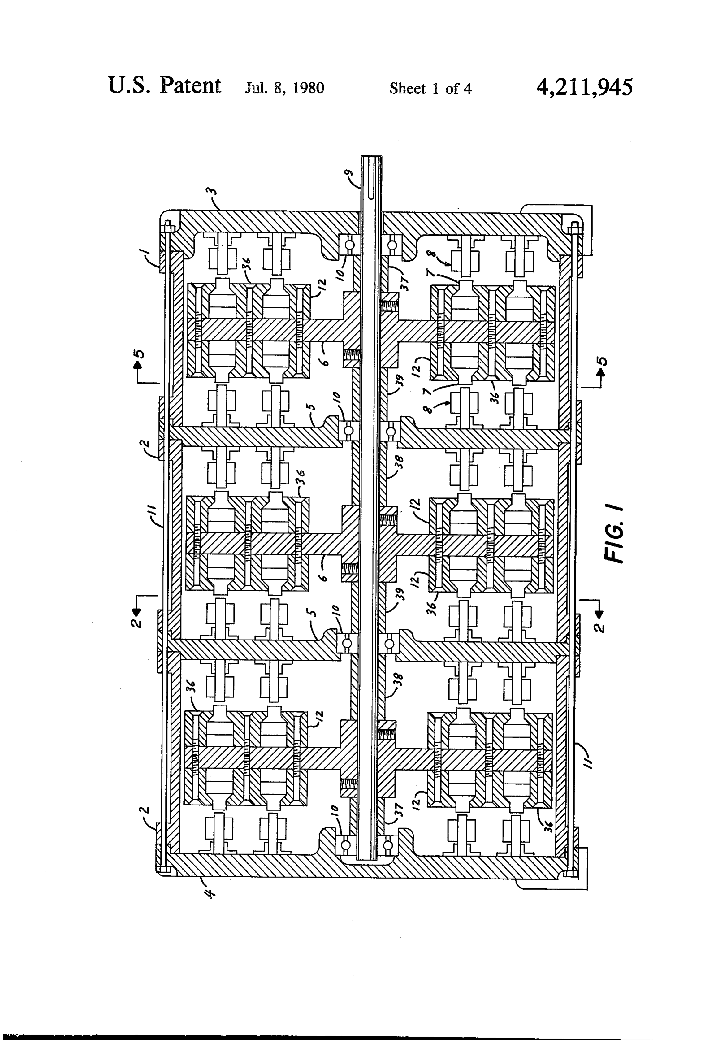
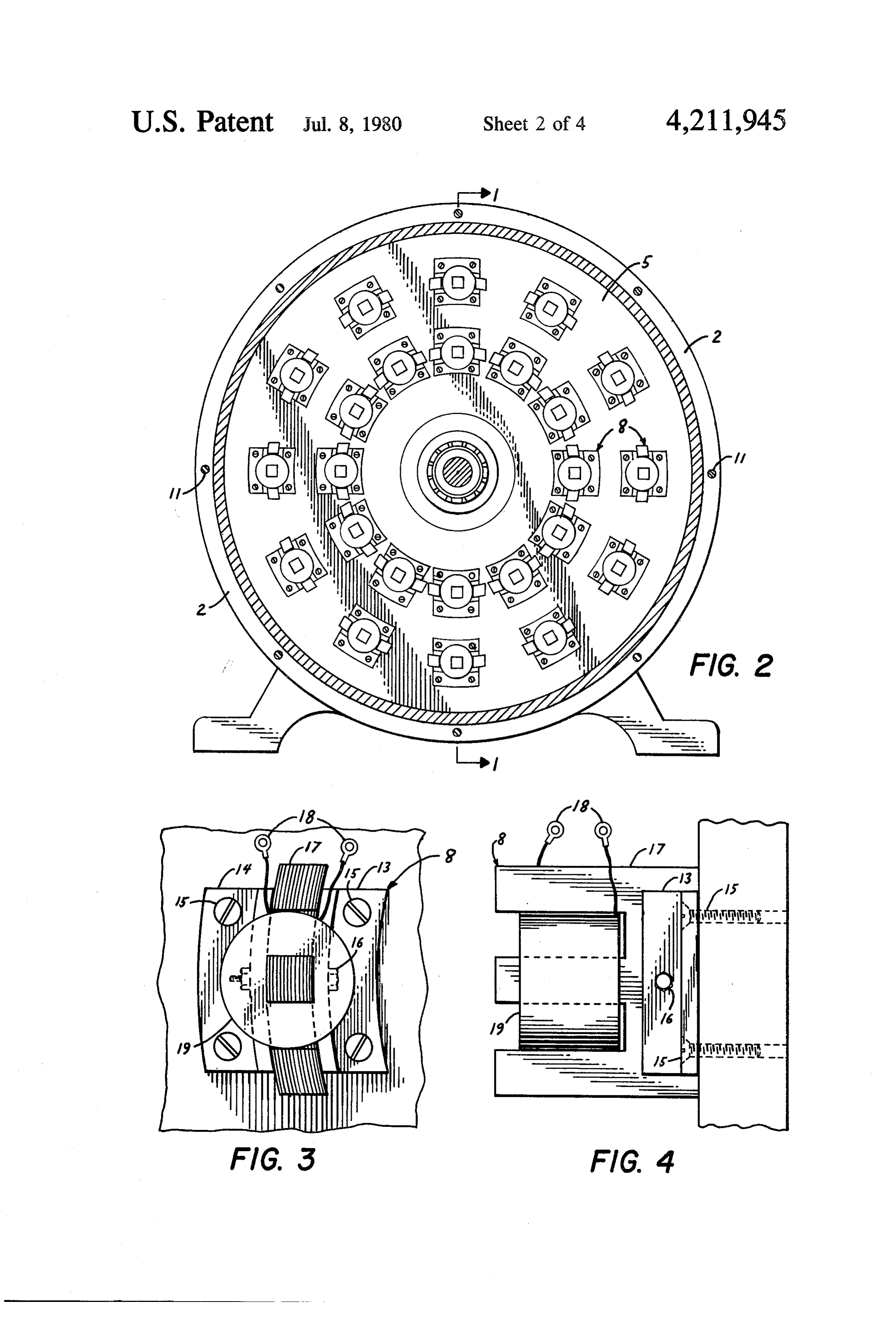
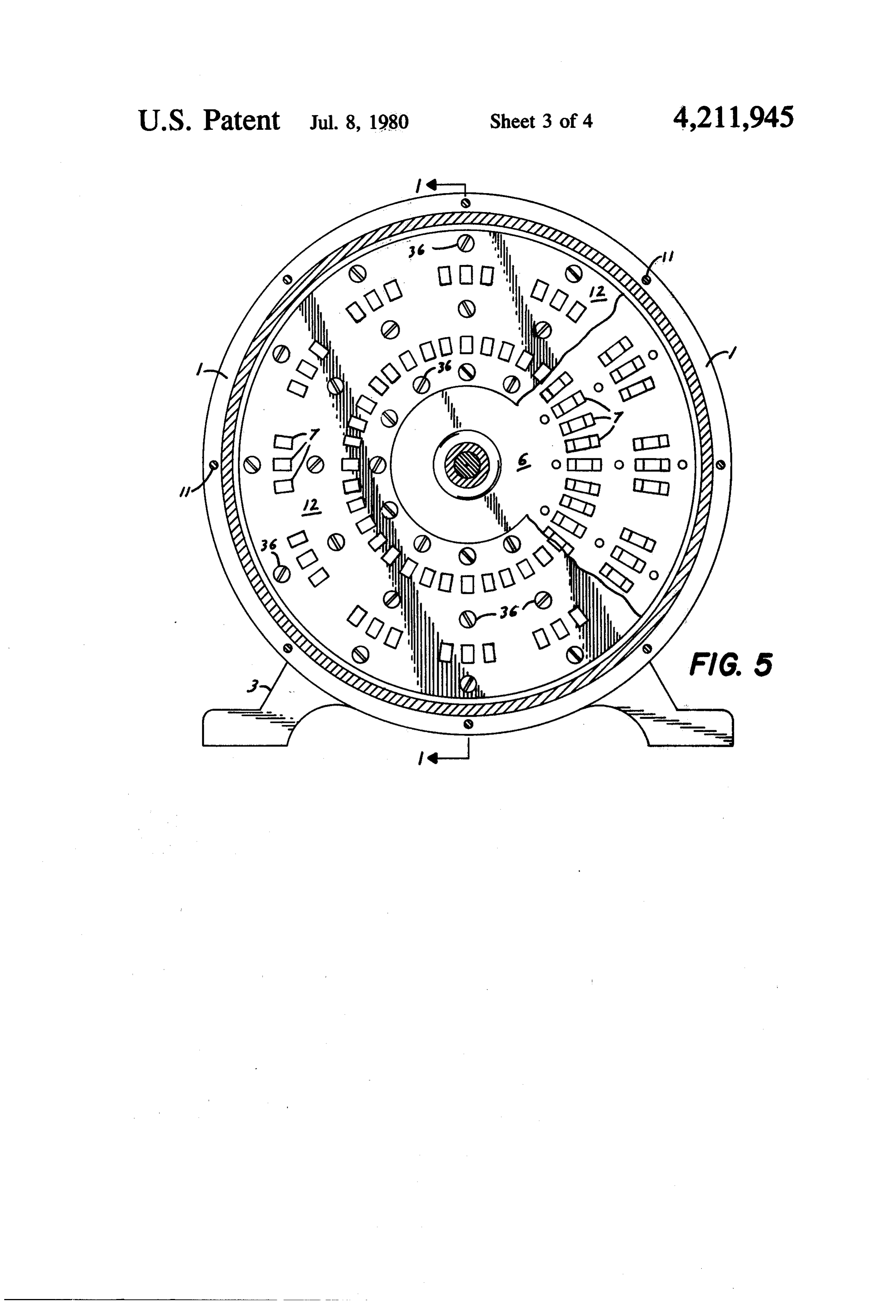
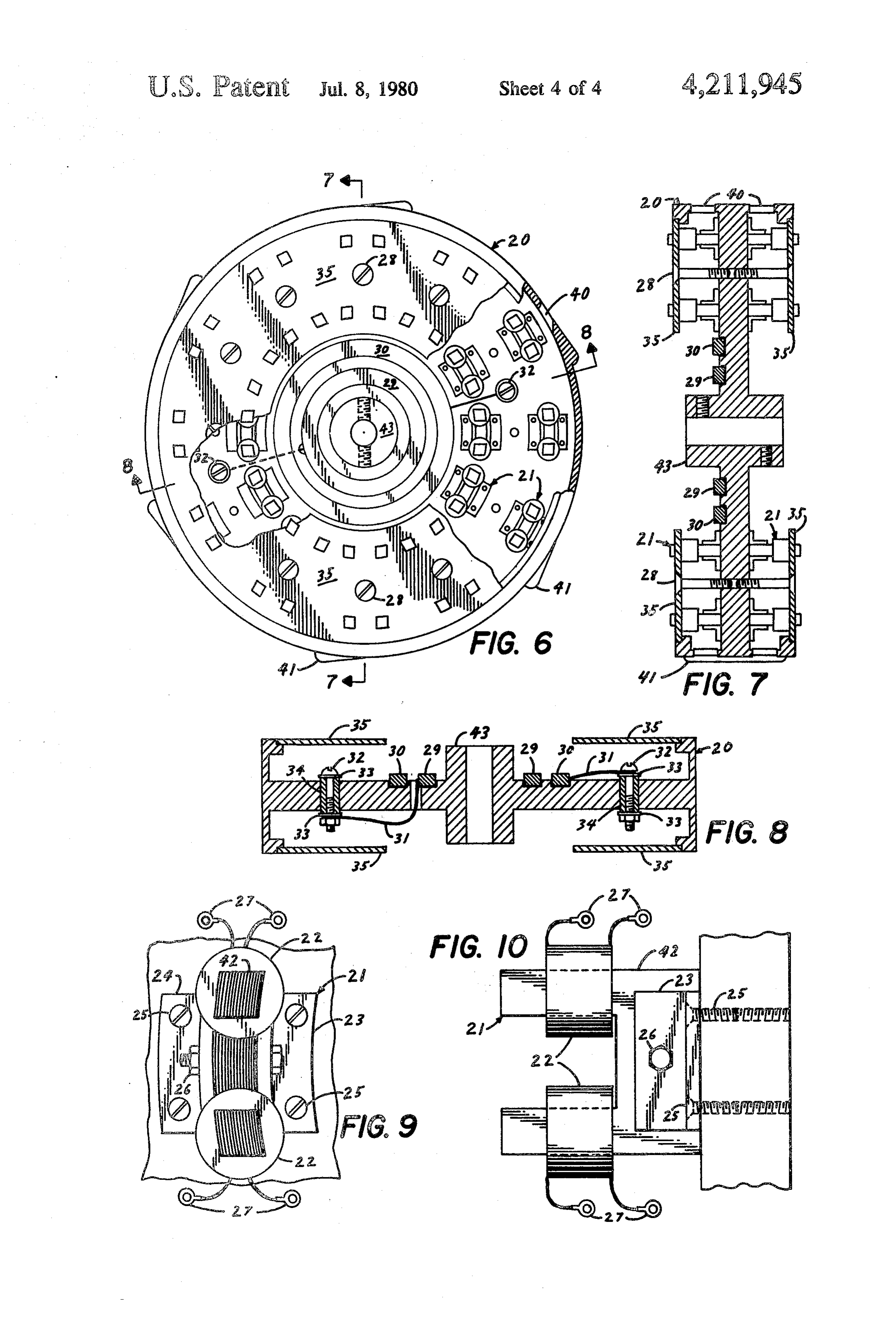
FIG. 5 is a cross sectional view taken on line 5-5 of
Page 2drawing sheetscan →
Page 3drawing sheetscan →
Page 4drawing sheetscan →
Page 5drawing sheetscan →
Page 6scan →
FIG. 5 is a cross sectional view taken on line 5-5 of
MULTI-VOLTAGE AND MULTI-FREQUENCY FIG. 1, showing the face of a rotor with the magnet ALTERNATOR/GENERATOR OF MODULAR locating cover in place and indicating a typical arrange CONSTRUCTION ment of permanent magnets to be used for high fre quency power generation (The relationship of field
This invention relates generally to dynamo electric magnets to stator coils is made apparent in this figure. machines and in particular to the alternating current With reference to rotor detail as reflected in FIG. 5, the type with the magnetic field being produced either by magnet arrangement should not be construed as limiting permanent magnets, electromagnets, or a combination the scope of the rotor design as it falls within the realm thereof. • 10 of the invention.);
An object of this invention is to provide an alter FIG. 6 is a face view of an alternative rotor to that nator/generator of modular construction wherein out shown in FIGS. 1 and 5 in which electromagnets have put capacities are increased simply by lineal or radial been substituted for the permanent magnets previously extension of standardized components. indicated, the magnet locating cover is shown in place, A further object of this invention is to provide electri 15 and in the broken areas, the field coil assemblies, are cal energy in multiple voltages and multiple frequen shown as viewed from their pole faces (Again, the mag cies, and combinations thereof, either simultaneously or net arrangement shown should not be construed as otherwise, from a single alternator/generator without limiting the scope of the invention.);
resort to conversion or inversion equipment or appara FIG. 7 is a sectional view taken on line 7-7 of FIG. tuS. 20 6 showing and indicating the rotor body, coil assem It is also an object of this invention to provide an blies, retaining devices and brush rings; alternator/generator to produce pulsating direct cur FIG. 8 is a further sectional view taken on line 8-8 rent electricity, either from a complete unit or from a of FIG. 6 showing the terminal posts for the distribution component of an alternator/generator, without re of energy to the field coil terminals;
course to output brushes, diodes or other means of in 25 FIG. 9 shows a field coil assembly as viewed from the version. - pole faces and indicates securing devices and coil termi Another desireable feature of this invention is that its nals; and design concept lends itself to mass production methods FIG. 10 is a side elevational view of FIG. 9 and whereby key components can be machine produced for shows further details of the field coil assembly. simplified assembly, thereby lowering production costs 30 Referring to the drawings and to FIG. 1 in particular, and manufacturing time. To those experienced in the it will be noted that the end of casing segment 1 is pre art, the following additional advantages would be self pared to receive an end plate 3. In the event that an evident: .. r alternator/generator of a particular output requires Stator design ensures a maximum of active material in only one rotor 6, end plate 4 would be substituted for the magnetic circuit; only terminal leads are outside the 35 intermediate stator support plate 5. influence of the magnetic field. An assembly consisting of casing 1, end plates 3 and Stator design allows generous exposure of active 4, when complete with bearings 10, suitably propor material to ambient and provides extensive heat sink tioned shaft 9 and appropriately dimensioned tie rods 11 capability, thereby accelerating heat "carry-off" with would define the structural confines of a single rotor resultant component life extension. alternator/generator.
Modular construction concept allows for installation FIG. 1 also shows the following: stator "coil-pole' of intermediate shaft bearings, resulting in greater rotor assemblies 8, permanent magnet assemblies 7, perma stability. nent magnet locating and retaining cover 12, permanent Design concept allows for access and replacement of magnet locating and retaining coversecuring screws 36, individual magnets, coils and bearings without disas 45 and rotor-bearing locating sleeves 37, 38 and 39. Bear sembly of overall unit. ing locating sleeves would be of suitable longitudinal Design concept lends itself to low-speed operation dimension to allow for interchanging of end and inter when this characteristic is desireable or an otherwise mediate stator support plates. Further indicated in FIG. important consideration. 1 are casing segments 2.
The foregoing and other objects and features of this 50 A further study of FIG. 1 will show how the alter invention will be more easily understood by those nator/generator output capacity may be increased by skilled in the art from the following non-limiting, de simple addition of intermediate stators and rotors when tailed description, when taken in connection with the accompanied by increase in shaft and tie rod lengths. It accompanying drawings, in which: should be noted that while FIG. 1 indicates field energy FIG. is a longitudinal sectional view showing the 55 in the rotor as being furnished by permanent magnets, principal and significant features of the invention. In the substitution of an electromagnet type rotor as fur this figure, the magnetic field is indicated as being fur ther detailed in the disclosure may be readily effected. nished by permanent magnets. For purposes of clarity, A further modification to the details as indicated in only representative permanent magnets, stator coils, FIG. 1 contemplates the omission of locating sleeves 37, and their assemblies are shown; 60 38 and 39 and the substitution of split-sleeve type bear FIG. 2 is a view of a stator taken on line 2-2 of FIG. ings for those indicated. This modification together 1, showing one of the multitude of stator coil arrange with suitably sized removeable covers located on the ments possible within the inventive concept; casing segments 1 and 2 would facilitate replacement or FIG. 3 is a plan or face view of a stator coil assembly; maintainance of unit components.
FIG. 4 is a side elevational view of a stator coil as 65 In FIG. 2 a representative arrangement of stator coil sembly showing the tooth-type pole pieces, coils with assemblies 8 is indicated and disposed about the face of terminals, and retaining detail of the pole piece assem a support plate 5. It would appear evident that this is not bly; representative of a finite quantity or arrangement of 7 coils which could be disposed on a multiplicity of pitch FIG. 9 shows details of field coil assembly 21 com circles and in a great variance of quantities and angular prising field coils 22, field coil pole piece 42, pole piece orientation as indicated by design conditions. This flexi retainers 23 and 24, as well as retainer securing screws bility of design scope is a benefit explained elsewhere 25. Also shown is pole securing bolt 26 and field coil herein.
terminals 27. It should be noted that the laminated pole
In FIG.3 a detail of a stator "coil-pole' assembly 8 is pieces 42 are curved to coincide with the stator pole shown. The three-toothed laminated pole piece 17 is in pitch circle.
evidence as is the output coil 19, coil terminals 18, pole retainers 13 and 14, pole retainer screws 15, and pole theFIG. 10 is an elevational view of FIG. 9, presented in interest of clarity and shows greater detail of the securing bolt 16. 10 means for securing the field coil assembly 21 to the FIG. 4 is an elevational view of FIG.3 and provides rotor 20.
greater clarity of detail. A rotor 6, of disc or flywheel configuration, as indi FIG. 5 is a sectional view showing a permanent mag cated net type rotor face, and the relationship of the perma shaft 9,insupported the drawings, suitably affixed at its hub to a in bearings 10, is rotated by a driver nent magnets 7 to the stator coil assemblies 8 shown in 15 (not shown) such as a reciprocating engine or turbine. FIG. 2 is in evidence. Pitch circles at permanent magnet In one mode of function (delineated as Option #1), a centers are in coincidence with pitch circles of the coil series or plurality of permanent magnets 7 arranged assemblies.
It will be noted that there are three permanent mag about the face or faces of the rotor 6 and suitably se cured thereto are made to revolve in such manner that net stacks per coil shown in FIG. 5, this number being 20 their orbital paths are in coincidence with a series or coincident with the number of teeth on each coil assem plurality of tooth-shaped pole pieces 17 of magnetic bly. material about which, in a manner as detailed in the It is assumed that the polarity at the permanent mag drawing, net faces is alternately north and south, this being one affixed. an induction coil 19 of conducting material is arrangement considered to achieve flux linkage in order 25 The magnetic pole pieces 17, together with the con to produce lines of force in the magnetic circuit.
While the drawings indicate the permanent magnet ducting coils 19, are rigidly secured to a stationary structure (the stator plate 5) and arranged on pitch on either face of the rotor as being in radial alignment, this is not necessarily a feature of the invention and circles coincident with the pitch circles on which the rotor field magnets 7 are arranged.
staggered orientations are also possible. 30 To those experienced in the art, and when considered In further reference to the permanent magnets, it is with the details provided in these drawings, it is obvious not an essential of the invention that they be restricted that the cooperation between the field magnets 7 (par to the size, shape or quantities indicated, since other ticularly when arranged in alternate polarities) and the variations fall within the scope of the invention. stator poles 17 would result in the production of electri In further consideration of FIG. 5, the permanent 35 cal energy due to the cutting of the lines of magnetic magnet locating and retaining cover 12 is shown in flux produced in the magnetic circuit.
location as are its securing screws 36. Also indicated in It is also apparent that electrical energy produced by FIG. 5 is the location of tie rods 11 and a detail of the the individual coils 19 could be led to bus bars (not alternator/generator feet which are an integral part of shown) or other external conductors in a great variety end plates 3 and 4. 40 of voltages and capacities dependant upon the number In FIG. 6 a rotor 20 equipped with electromagnetic field coil assemblies 21 is indicated. Again, the arrange of coils employed and/or the manner of the wiring arrangements such as connecting the coil terminals in ments of the magnets is general, and do not restrict the parallel or in series, or in combinations thereof. scope of the invention. Also shown in FIG. 6 at the External switching apparatus connecting to alter rotor face are two field coil input transfer rings 29 and 45 nator/generator terminals could also be employed to 30 by which direct current from a convenient source is effect changes of voltages and output capacities while relayed from brushes (not shown) to the field coils 22. the alternator/generator is operating under "on line' Terminal posts 32, to which the individual field coil conditions.
terminals 27 connect, are also shown. It will be noted that the peripheral rim of the rotor incorporates lobes 50 andBynumber variations in field magnet polarity, arrangement of field magnets employed, a wide range of 41 designed to create an area of low pressure at their frequencies can be obtained from a single alternator/- trailing edges in order to draw cooling air through slots generator.
40 as indicated in the broken area at the rotor rim. As in By unipolar arrangement of field magnets, pulsating FIG. 5, the relationship of field magnets to stator coils direct current could be produced from single or multi is in evidence. 55 ple stator arrangements, and if required, simultaneously In FIG. 7, which is a sectional view of FIG. 6, greater from a single unit together with alternating type cur structural detail of the rotor 20 is indicated. Details ret.
provided include the means whereby field coil assembly In considering the overall concept as set forth herein, locating and retaining cover 35 is secured to the rotor it would also be apparent that an alternator/generator body by securing screws 28. Also shown are threaded 60 could be produced with bearings provided at intermedi holes for set screws whereby the rotor hub 43 may be ate support plates, and that adequate openings provided secured to the alternator/generator shaft 9.
In FIG. 8, field coil input transfer rings 29 and 30 are replacement of individual would along the length of a unit allow for testing and components without disas indicated as being cemented in insulated grooves on one sembly of the unit.
face of the rotor 20. Terminals 31 lead the field coil 65 Moreover, the flexibility allowed by the unique sta input energy from the rings 29 and 30 to terminal posts tor-rotor concept makes it possible to construct units of 32 which are insulated from the rotor body by insulat greatly varying diameters, lengths and outputs while ing washers 33 and insulating sleeves 34. employing standardized, mass-produced active compo 8 nents. Additionally, the ease with which unit diameters 2. An alternator/generator of modular construction, may be varied at design level allows for a wide range of comprising:
driver speeds including very low speeds with the atten (a) a plurality of stator plates located in spaced-apart dant advantages of extended unit life expectancy. parallel planes, each stator plate carrying a series of In the second mode of function (delineated as Option electrical output coils, each output coil being part #2), a rotor 20 employing electromagnets 21, rather of an assembly including a pole piece of magnetic than the permanent magnets as used in Option 1901, is material fixed to its respective stator plate, the substituted. cross-sectional area of each pole piece being Direct current electricity to energize the electromag 10 smaller than the cross-sectional area of each field nets 21 is led from a convenient source to brushes af. magnet, fixed to an axially oriented arm extending toward the (b) a rotor disc located between, and parallel to, each rotor from the stator support plates. Electrical energy two successive stator plates, each rotor disc carry from the brushes is transferred to the field coils 22 ing a series of field magnets cooperable with said through the medium of the brush rings 29 and 30 shown 15 (c)output a coils carried by adjacent stator plates, rotatable shaft carrying all said rotor discs, said in the drawings. shaft passing through said stator plates, In all other respects, the function of the invention (d) bearing means carried by the two endmost stator conforms to Option #1 except that Option #2 offers plates and by at least some of said stator plates even greater flexibility, since field strength may be var between the endmost plates, said shaft being rotat ied for even greater control and variety of output condi 20 ably supported by said bearing means, tions. (e) a plurality of individual casing sections, one of Having made the disclosure as set forth herein, in said casing sections being between each two suc cluding certain mechanical arrangements as shown in cessive stator plates, and the drawings, which are merely indicative of certain (f) means for securing said casing sections and stator approaches contemplated by my invention, and being 25 plates together to define a housing enclosing all the aware of the many modifications possible in an operat rotor discs.
ing unit and the many modifications likely to appear to 3. An alternator/generator as defined in claim 2 those skilled in the art, it is accordingly stated that my wherein each pole piece includes a plurality of teeth, invention is not limited to the embodiments illustrated said output coil surrounding at least one of said teeth, and described herein, but further includes all modifica 30 and tooth.
wherein a field magnet is axially aligned with each tions and variations as may fall within the scope of the 4. An alternator/generator as defined in claim 2 following claims.
What is claimed is: wherein said pole pieces are fixed to their respective 1. An alternator/generator of modular construction, 35 curvedstator plates in a circular pattern, each pole piece being comprising: to conform to the radius of curvature of said (a) a plurality of stator plates located in spaced-apart circular pattern.
alternator/generator of modular construction, parallel planes, each stator plate carrying a series of comprising:
pole pieces having fingers, said fingers carrying (a) a plurality of stator plates located in spaced-apart electrical output coils, 40 parallel planes, each stator plate carrying a series of (b) a rotor disc located between, and parallel to, each electrical output coils.
two successive stator plates, each rotor disc carry (b) a rotor disc located between, and parallel to, each ing a series of field magnets cooperable with said two successive stator plates, each rotor disc carry output coils carried by adjacent stator plates, the ing a series of field magnets cooperable with said number of said field magnets on each face of a rotor 45 output coils carried by adjacent stator plates, disc being equal to the number of said pole piece (c) lobes on the periphery of each rotor disc for creat fingers on an opposite face of an adjacent stator ing a low pressure region at one end of each lobe, plate, and each of the field magnets carried on each and a slot at the low pressure region through which face of said rotor disc being aligned in the axial air flows radially inwardly to cool said field mag direction of said shaft with one of said pole piece 50 nets, fingers on an opposite face of an adjacent stator (d) a rotatable shaft carrying all said rotor discs, said plate when said rotor disc is in a stationary posi shaft passing through said stator plates, tion, (e) bearing means carried by the two endmost stator (c) a rotatable shaft carrying all said rotor discs, said 55 plates and by at least some of said stator plates shaft passing through said stator plates, between the endmost plates, said shaft being rotat (d) bearing means carried by the two endmost stator ably supported by said bearing means, plates and by at least some of said stator plates (f) a plurality of individual casing sections, one of said between the endmost plates, said shaft being rotat casing sections being between each two successive ably supported by said bearing means, stator plates, and (e) a plurality of individual casing sections, one of 60 (g) means for securing said casing sections and stator said casing sections being between each two suc plates together to define a housing enclosing all the rotor discs.
cessive stator plates, and 6. An alternator/generator as defined in claim 5 (f) means for securing said casing sections and stator wherein each of said lobes has the shape of the upper plates together to define a housing enclosing all the 65 half of an airfoil.
rotor discs. it k it k sk
Provenance
- Collection
- Patents citing this work
- Pages
- 8
- Method
- pdftotext (the PDF's own text layer) + pdftoppm 300dpi page scans
- Patent office record
- patents.google.com →
- Source
- Google Patents citing-documents table
- Assignee
- Gen-Tech, Inc.
- Published
- 1980-07-08
- Transcribed from
- patentimages.storage.googleapis.com →