

patent · US4219009A
Vented solar panel
26 August 1980
Text
Page 1scan →
United States Patent (19)
Palmer
(54) vented solarpanel
76) Inventor: David W. Palmer, 109 Phillips Ave.,
Rockport, Mass. 01966
51) int. C.? ............................ F24J 3/02; F24F 7/00 52 U.S. C. ...................................... 126/422; 137/79;
246,626 9/1881 Morse ................................... 126/270 2,109,114 2/1938 Kerr ......... ... 251/294 2,776,796 1/1957 Mosely . ... 236/93 A 3,690,336 9/1972 Drum ..................................... 137/75 3,726,299 4/1973 Wheatley ............................... 137/75 3,943,911 3/1976 Yu ............ ... 126/271 3,949,732 4/1976 Rienes ...... ... 126/422 4,026,267 5/1977 Coleman .. ... 126/270 4,029,258 6/1977 Groth........... ... 126/270 4,043,317 8/1977 Scharfman ..... ... 126/270 4,046,134 9/1977 Scott ...................................... 236/49
4,058,109 11/1977 Gramm ................................ 126/270 4,063,545 12/1977 Hapgood ................................ 165/11 4,150,659 4/1979 Buckley ............................... 126/422 Primary Examiner-James C. Yeung
Assistant Examiner-Daniel O'Connor
Attorney, Agent, or Firm-Peter N. Jansson
A solar panel having venting gates at opposite ends of an air plenum defined between a collector element and a protective, light-transmissive cover and having a wax thermal actuator for both the gates and flexible force transmitting linkages between the actuator and each gate to operate the gates simultaneously. Preferred em bodiments include certain linkages, gates and gate con trol apparatus, and certainstructural relationships of the actuator with the collector element to achieve desired heat transfers. In certain embodiments, the actuator is part of a heat-sensing module which receives a multi plicity of heat inputs. The collector element in certain highly preferred embodiments is of plastic. A glazed solar panel having a venting gate controlled by a tem perature-responsive wax thermal actuator linked thereto.
39 Claims, 5 Drawing Figures
Drawings
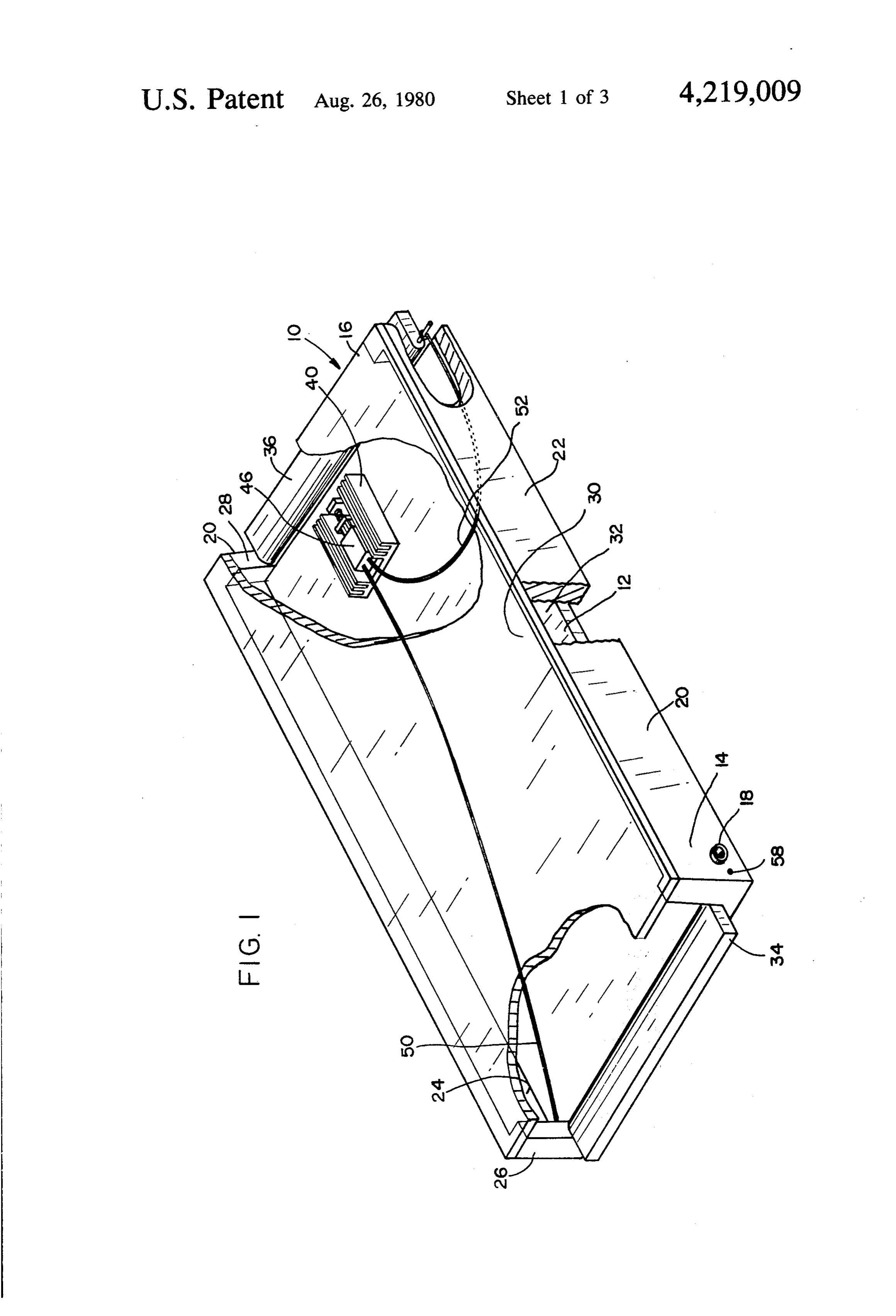
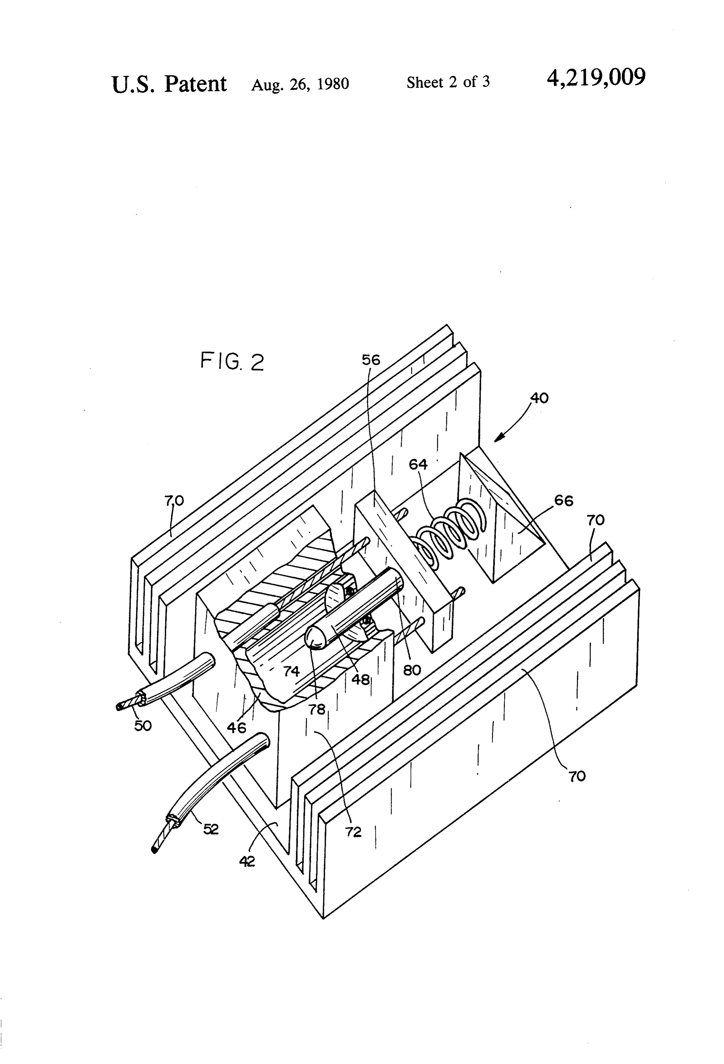
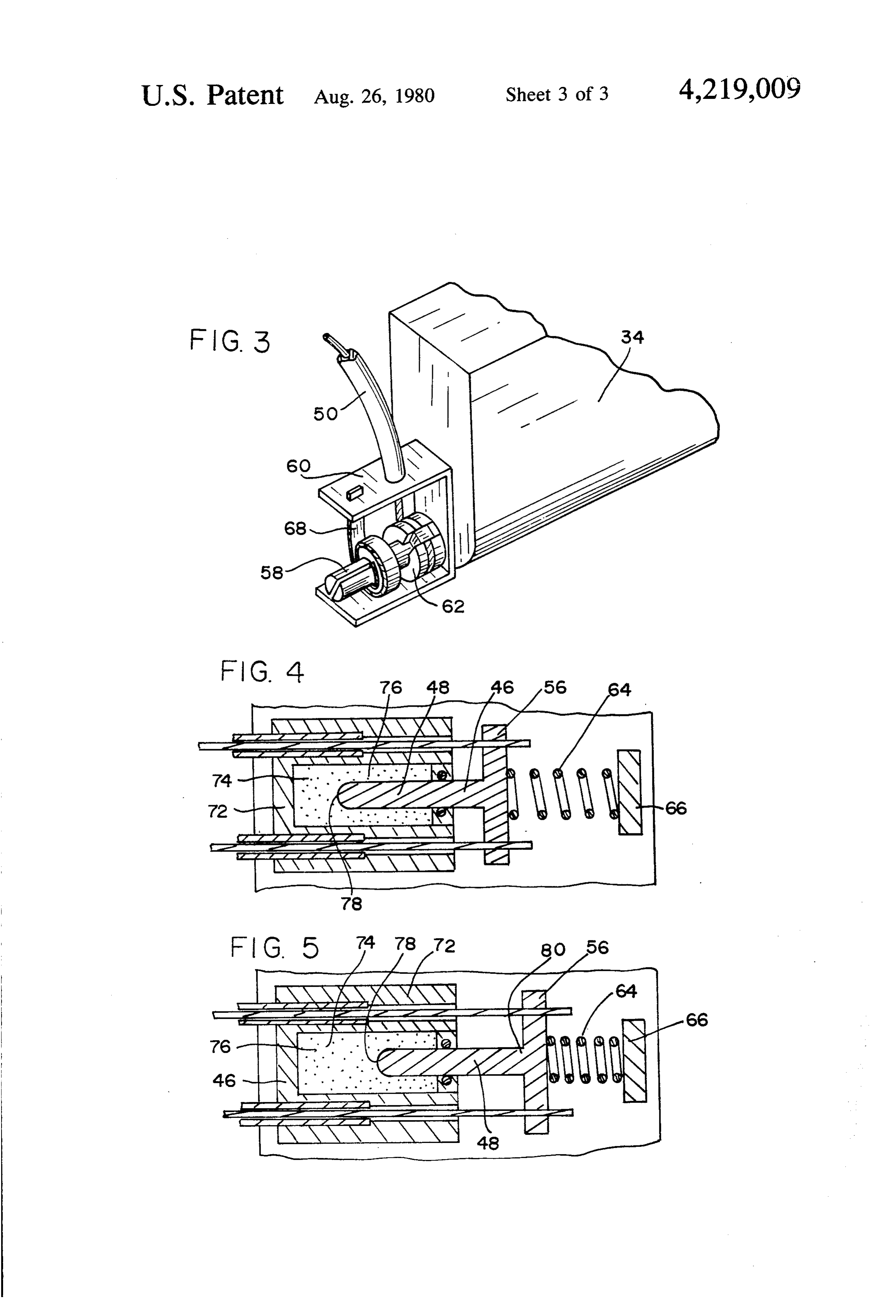
FIG. 1 illustrates the venting position, in trol having sufficient forcefulness to operate venting 10 which the gates are wide open. When the gates move gates extending across the width of the panel.
Page 2drawing sheetscan →
Page 3drawing sheetscan →
Page 4drawing sheetscan →
Page 5scan →
systems have failed because of electrical power outages
VENTED SOLARPANEL or other problems. . -
Attempts have been made to develop means of vent
BACKGROUND OF THE INVENTION ing the air plenum between the solar collector and the This invention relates to solar panels, such as panels 5 cover when overheating occurs to allow the hot air for heating water and the like, and, more particularly, to adjacent to the overheated collector element to escape solar panels which have vented air. plenums, typically from the air plenum and be replaced by cooler air from above the collector element, to eliminate overheating. the atmosphere, thus retarding heat buildup and allow Solar panels have been used to collect solar energy 10 ing the collector element to cool to acceptable tempera for space heating, water heating and a variety of other ture levels. None of the efforts prior to the instant in applications requiring heat energy. Solar panels of this vention, however, have resulted in a practical and effec type typically have a collector plate or other collector tively operating vented solar panel. element which is of a color (black or other dark color) In certain solar panels of the prior art, temperature and/or texture to maximize absorption of solar radia 15. responsive bimetal valves or dampers have been placed tion. Such collector elements have fluid conduits, often at opposite ends (the lower and upper ends, considering a large number of parallel conduits, disposed in efficient panel tilt) of the panel. Such arrangements have been conductive heat-transfer relation thereto. Often the unsatisfactory for several reasons. In such panels, the conduits are formed integrally with the collector ele temperature-responsive valves at either end operate ment. A fluid, usually a liquid, flows (aided normally by separately rather than in a coordinated manner. a remote pump or fan) through the conduits and is 20 The opening of such valves at widely differing times heated by taking heat from the collector element. This occurs because of the temperature differences between heated fluid may be used in a variety of ways, either the lower and upper ends of the panel. In many cases, directly (for example, as domestic hot water) or for a the isolation of the collector element of such a vented subsequent heat transfer for some other purpose such as panel would be breached without allowing proper vent space heating. The fluid passing through such conduits 25 .ing; such breach, while serving no useful purpose, may be referred to as the "working fluid'. would allow some unwanted ingress of dirt or dust, Often, particularly in cold climates, a glazing, that is, particularly near the opened valve. In other cases, vent a solar energy-transmitting cover, is placed over the ing would stop prematurely because of premature clos collector element in closely spaced relation thereto.
This cover is usually supported by a frame of some sort, 30 ing of one of the temperature-responsive valves, before sufficient cooling occurs. While the lack of coordina and forms an air plenum chamber which isolates and tion of separately operable venting valves at opposite insulates the collector element from the environment to minimize undesirable heat loss. The instant invention is ends of the solar panel could be avoided by leaving one applicable to solar panels of this general type and to any end of the solar panel open at all times, such would only Solar panel which has an air plenum adjacent to a col 35 reduce the efficiency of panel operation and exacerbate lector element. The invention relates to the need to vent the problem of ingress of dust and dirt. such air plenum whenever destructive overheating A further problem with some of such temperature must be prevented. responsive valves is that, even when valves at both ends Such solar panels may be mounted on a roof or other are open, the venting is insufficient to allow flow of air structure in position to receive solar radiation. Panels of 40 across substantially the entire width of the solar panel. this type are often generally flat and rectangular, and Instead, flow may occur primarily near the line extend are often mounted at a substantial tilt or angle with ing between the bimetal valves at either end of the respect to the horizontal to be facing the sun as directly panel, leaving other portions of the panel substantially as possible. In many cases, several panels may be uncooled.
ganged together to increase collection of solar radia 45 Another drawback of the bimetallic valve venting tion. devices is that the bimetallic temperature sensors are at A major problem with covered solar panels of the or near the opening, normally an integral part thereof. type described is excessive heating. If the temperature No flexibility of sensor placement is available. of the solar collector and/or the entire panel rises above Another major problem of prior glazed solar panels is certain levels, a great deal of damage can occur. Of 50 their high cost. Glazed solar panels are generally of course, the temperatures which are tolerable depend on expensive materials and construction. The collector the materials and construction of the panel. Differing elements are often of expensive metal materials chosen thermal expansion coefficients of materials used in the to avoid corrosion. Some glazed solar panels of the panel may result in the breaking of bonds and joints. prior art have complicated, powered control systems to And, if the working fluid in the conduits vaporizes, the 55 prevent problems. Such systems are generally quite pressure may increase to the point of rupturing the expensive, and are also subject to failure because of conduits, thus causing leakage in the system. Very high power outages.
temperatures for long periods of time may cause perma To reduce high panel cost, plastic collector elements nent distortions in the collector element (particularly could be used. Plastic collector elements, however, metal collector elements) and related parts and can even undergo much greater dimensional changes than simi cause melting of plastics and combustion of combustible larly shaped metal elements, and use of such elements materials. would place constraints on panel construction, and on Overheating of a solar panel can arise from several -any control systems forming a part thereof. failures in the system, such as a blockage or other failure In summary, there has been need for a relatively in the circulation of the working fluid, pump failure, 65 low-cost, efficiently operating, and practical vented power failure, or malfunctioning of the solar panel con solar panel. There has been need for a vented solar trol system. Various systems have been made to protect panel with a reliable heat-sensing device and vent con solar panels from overheating. However, many of these trol system. .
Page 6scan →
hereinafter, and act on the gates through the flexible
BRIEF SUMMARY OF THE INVENTION linkages.
This invention solves the problems and fills the needs While major heat input to the wax thermal actuator mentioned above, providing an efficiently operating, may be by conduction, in some embodiments the actua practical vented solar panel. The solar panel of this tor is part of a heat-sensing module which includes invention has a reliable heat-sensing device and vent heat-transfer fins within the air plenum. The fins in control system, which is totally sun-powered. The solar crease the amount of heat which may be transferred to panel of this invention, particularly certain preferred or from the module by convection as air within the embodiments, is a relatively low-cost and trouble-free plenum contacts the module. With such an arrange device. O ment, actuation of the wax thermal actuator to open the The invention includes the use of a in its place actua vent gates can readily occur even though the portion of tor as the control for all required venting gates in the the solar panel including the module may be shaded. panel. In a highly preferred embodiment, in its place And, when the venting gates are open, the fins will - actuator is in heat-transfer relation with the collector facilitate cooling of the actuator, thus preventing the plate and controls gates at opposite ends of the air ple 15 solar panel from cooling so much that efficient opera num by means of flexible force-transmitting linkages tion is impaired.
extending between the actuator and each of the gates. The increase in convective heat transfer is usually of The actuator and linkages serve to operate the gates greater importance when a plastic collector element is simultaneously, to eliminate substantial problems and used, because of the lower thermal conductivity of disadvantages of vented panels of the prior art. The wax 20 plastics (compared to metal). The module itself, in most thermal actuator generates sufficient force to operate arrangements, shades a small portion of the collector, two large gates extending substantially across the width and conductive heat transfer from the hotter, unshaded of the panel at either end thereof even though the actua portions of the collector to the module through the tor is remote from the gates. The force-transmitting shaded portions of the collector in contact with the linkages must be flexible to accommodate dimensional 25 module would be somewhat limited. Thus, with the variations in the panel between the actuator and the gates due to thermal expansion and contraction. Con venting gates closed, circulation of hot stagnant air trol cables (that is, sheathed mechanical cables such as the moduleairandplenum within the its wax is an important means of heating thermal actuator.
bicycle cables), can accommodate great dimensional In some preferred embodiments, the heat-sensing variations, making possible effective operation of gates 30 module which are remote from the actuator, even in panels face) formay be adapted (such as by darkening its sur substantial absorption of solar radiation. This having collector elements of highly expandable plastics. may be useful, particularly
In preferred embodiments of this invention, the gates collectors, for substantiallyin the solar panels having plastic same reasons as men are pivotable with respect to the remainder of the struc ture and operate as torque is applied by means of the 35 tioned above.
The heat-sensing module, when it is adapted to ab linkages. A linkage is secured relative to its gate at a sorb solar radiation, has fins for convective heat transfer radial position near the axis of the pivot for the gate. from the air plenum, and is in conductive heat-transfer This serves to amplify the gate-opening movement relation available from lineal movement of the linkage. It has grator oftoconductive, the collector, functions as a summing inte convective, and radiative heat been determined that wax thermal actuators have suffi 40 cient force to reliably move the gates in this manner well transfer to the actuator. This arrangement functions through flexible linkages. in sensing overheating at any portion of the solar Certain preferred embodiments include one or more vents panel and responding by ready venting and closing of springs or other means to bias the gates toward the solar panel. when and to the extent required to protect the positions closing the air plenum. In such embodiments, 45 the wax thermal actuator and linkages are arranged to The heat-sensing module may be located on the col pull the gates moving them toward the open (or vent lector plate at whatever point is deemed advantageous. ing) positions. Such biasing means, sometimes referred However, the module is preferably located near the to herein as first biasing means, may be two or more upper end of the solar panel, which is normally the separate springs or the like at the gates, but is preferably 50 hottest part of the panel.
a single-coil spring or the like arranged in relation with OBJECTS OF THE INVENTION the actuator to act on the gates through the linkages.
Some embodiments have, as an additional feature, sec It is the primary object of this invention to provide a ond biasing means, which is(are) weaker than the first vented solar panel overcoming problems and deficien biasing means, to move the gates to the open venting 55 cies of panels of the prior art.
position when the flexible force-transmitting linkages Another object of this invention is to provide a (between the elastomeric actuator and the gates) are vented solar panel which is totally sun-powered and disconnected or broken. The second biasing means ser thus not subject to power failure.
ve(s) as a fail-safe system against overheating of panels Another object of this invention is to provide a low should the linkages break. cost, glazed solar panel which is reliable in operation. The wax thermal actuator, which is in heat-transfer Yet another object of this invention is to provide a relation to the collector element, is preferably in heat vented solar panel which remains substantially closed conductive relation thereto, either in direct contact except when venting is required to counteract overheat therewith or through a preferably metallic module of ilg.
which it is a part. When the collector overheats, the 65 Still another object of this invention is to provide a heat is conducted into the wax thermal actuator. When vented solar panel with a heat-sensing device which unacceptable temperatures are reached, the actuator controls gates at opposite ends of the panel simulta will move with force, as will be more fully explained neously.
Page 7scan →
Another object of this invention is to provide a Lower end member 26 and upper end member 28 vented solar panel having a single temperature-respon include gates 34 and 36, respectively. Each of gates 34. sive control for two widely separated venting gates. and 36 is pivotally movable about an axis defined by Yet another object of this invention is to provide a rotation pins, such as rotation pin 58 shown in FIG. 1. vented solar panel which allows cooling across substan Gates 34 and 36 rotate with respect to the remaining tially the entire width of the collector plate. portions of the end members of which they are a part. Gates 34 and 36 are movable between first positions
Still another object of this invention is to provide a closing vented solar panel with a temperature-responsive con plenum air 32.
plenum 32 and second positions venting
FIG. 1 illustrates the venting position, in trol having sufficient forcefulness to operate venting 10 which the gates are wide open. When the gates move gates extending across the width of the panel.
A further object of this invention is to provide a FIG. 1, the gates wouldfrom through a 90° rotation the positions illustrated in close the air plenum thus end vented solar panel having a temperature-responsive ing venting therethrough. FIG. 3 shows gate 34 in the gate operator which undergoes substantial heat transfer closed by conduction, convection and radiation to overcome 15 Nearposition. to upper end member 28 and mounted in heat certain problems and provide reliable and efficient vent conductive contact with collector element 32 is heat Ing.
sensing module 40. Module 40 is illustrated in detail in
BRIEF DESCRIPTION OF THE DRAWINGS FIG. 2. Heat-sensing module 40 includes a base plate 42 These and other objects of the invention will be ap 20 inthermal full contact with collector element 12 and a wax actuator 46 resting on base plate 42. The wax parent from the following description of preferred em thermal actuator is the heart of the control system for bodiments wherein:
FIG. 1 is a partially cutaway perspective view of a both gates 34 and 36.
As used herein, the term "wax thermal actuator' solar panel according to this invention. means a device which uses the change of volume of a FIG. 2 is an enlarged, partially cutaway perspective 25 material undergoing a reversible solid-liquid phase view of a portion of the device of FIG. 1, specifically, change to generate displacement of a piston (usually, a the heat-sensing module. rod-like piston). Operation of a wax thermal actuator is FIG. 3 is an enlarged, perspective view of FIG. 1, illustrated in sufficient detail in FIGS. 4 and 5. Wax showing details of the gate-operating mechanism not thermal actuator 46 includes a rigid metal block 72 shown in FIG. 1. 30 which defines a chamber 74 filled with wax 76. Also in FIG. 4 is a sectional, partial top view of FIG. 2, chamber 74 is a piston 48 including proximal end 78 in illustrating that portion of the device when the solar contact with wax 76 and distal end 80 extending outside panel is below a predetermined unacceptable tempera chamber 74. In FIG. 4, wax 76 is in the solid state since ture. its temperature is below the phase change range. In FIG. 5 is a view similar to FIG. 4, differing only in 35 FIG. 5, all or some of the wax in chamber 74 has that it illustrates the device when the panel is at or melted, and, consequently, increased in volume. By its above a predetermined unacceptable temperature. increase in volume, the wax has displaced piston 48 DESCRIPTION OF PREFERRED outwardly, generating great force. When wax thermal EMBODIMENTS actuator 46 and hence its wax have cooled, wax 76 will solidify, decreasing in volume and allowing piston 48 to
FIG. 1 illustrates a solar panel 10 according to this be returned to some extent into chamber 74. invention. Solar panel 10 includes a collector element Wax thermal actuators may be obtained from a vari 12 which is a flat rectangular plate extending across ety of sources. Such actuators are used in automobile nearly the entire solar panel structure. Collector ele cooling systems and in a variety of other applications, ment 12 has working fluid conduits formed therein 45 and may be obtained from the same suppliers used in which are not shown. The conduits run parallel one to such other cases. Wax thermal actuators which utilize another from a first or lower end 14 of solar panel 10 to materials having a variety of phase-change temperature a second or upper end 16. The working fluid conduits ranges may be obtained. For example, wax can be for are joined at either end in manifolds for circulation mulated to melt at a temperature anywhere within the away from the panel for any desired purpose as previ 50 range of about 20° C. to 150° C. Usually, a wax mixture ously mentioned. The manifold outlet 18 for lower end will melt at a chosen temperature or within perhaps 3 14 is illustrated in FIG. 1; the manifold for upper end 16 C. over or under such temprature. As melting occurs, is not shown. piston 48 will be displaced by an amount proportional to Collector element 12 is mounted on a frame 20 which the amount of wax melted. The phase-change material includes parallel side members 22 and 24, lower end 55 should be chosen with reference to a predetermined member 26 and upper end member 28. All of the frame unacceptable temperature for the construction and ma members 20 are suitably insulated. Extending across the terials chosen for the solar panel. top of frame 20 and spaced from collector element 12 is As previously indicated, the movement of piston 48 is a solar radiation-transmitting cover 30, which is often accomplished with great force, and provides the work referred to as a glazing. Cover 30 serves to isolate col necessary to move gates 34 and 36 from the first or lector element 12 from the atmosphere, protecting it closed positions to the second or open positions simulta against unnecessary heat loss while allowing radiant neously. The movement provided by actuator 46 is heat to enter. transmitted simultaneously to gates 34 and 36 by means Cover 30 defines, with frame 20 and collector ele of flexible force-transmitting linkages 50 and 52, respec ment 12, an air plenum 32. Under working conditions, 65 tively. The term "flexible force-transmitting linkage' as the air in air plenum 32 does not circulate, but remains used herein means a linkage which can transfer the in place isolating and insulating collector element 12 strong force of the wax thermal actuator to the gates from the atmosphere. and do so effectively in spite of dimensional variations 8 between the actuator and the gates it controls. Such installed with respect to gate 36 at upper end of frame linkages include slack to accommodate changes in the 20.
distances between the actuator and the gate or gates it Elastomeric actuator 46 is in heat-conductive relation controls. When the distance is reduced there is in to collector element 12 by means of its contact there creased slack; when the distance increases there is re with through base plate 42 of heat-sensing module 40. duced slack. In the highly preferred embodiment shown Module 40 includes heat-transfer fins 70 extending up in the drawings, linkages 50 and 52 are control cables. wardly from base plate 42 in parallel, spaced relation The term "control cable' as used herein refers to the ship one to another. Fins 70 extend in a direction be sheathed coaxial mechanical cables commonly known tween lower end 26 and upper end 28 of panel 10. When as bicycle cables. A variety of other flexible force-trans 10 gates 34 and 36 are open, a "chimney effect' air flow is mitting linkages could be used effectively. established from gate 34 at the lower end of panel 10 to As shown best in FIGS. 2, 4 and 5, the sheathings 54 gate 36 at the upper end of panel 10. The flow is caused of control cables 50 and 52 are secured to mounting by the hot air within plenum 32 rising through gate 36 block 72 at one end of each of the cables 50 and 52. The causing cooler air to be drawn into air plenum 32 movable inner portion of cables 50 and 52 at that end 15 through gate 34. This air flow will move between fins are secured to a yoke 56 which is attached firmly to 70, thus increasing effective heat transfer with actuator distal end 80 of piston 48. The other ends of cables 50 46. Fins 70 will also allow increased convective heat and 52 are secured relative to gates 34 and 36, respec transfer when gates 34 and 36 are closed, as air circu tively, and apply a torque thereto in a manner not 20 advantageslates within air plenum 32. Thus, fins 70 provide the shown fully in FIG. 1. described above. The connection of the cables with respect to the gates in Module 40 has its upper surface darkened or adapted other known fashion to absorb substantial amounts of is fully illustrated in FIG. 3. As shown in that figure, solar cable 50 is secured relative to gate 34 at a radial position functions radiation. Heat-sensing module 40, therefore, near the axis of pivot pin 58 such that linear movement vective, and as a summing integrator of conductive, con of the inner portion of cable 50 is amplified in the gate 25 transfer radiative heat transfer. Each of these heat opening movement. Sheathing 54 of cable 50 is firmly sons described relationships is significant for the various rea attached to mounting bracket 60 which is secured in module 40, andabove. thus
Primary heat transfer to and from actuator 46, can be by conduction turn to a portion of lower end member 26 adjacent to from collector plate 12. However, the fins increasing gate 34. The extreme end of cable 50 at gate 34 is 30 convective heat transfer and the adaptation wrapped partially around a rotation drum 62 which is 40 to increase absorption of solar radiation areofpreferred module fixed to pivot pin 58.
When an unacceptably high temperature is reached, for more reliable and efficient functioning of the solar panel venting system.
piston 48 of actuator 46 moves outwardly (to the right Collector element 12 of solar panel 10 is preferably as shown in FIGS. 1, 2, 4 and 5), causing the inner 35 made of a plastic such as polycarbonate, poly(2,6- portion of cable 50 to be moved such that it is effec dimethyl-1,4-phenylene oxide) (sold by General Elec tively unwound from rotation drum 62 to cause gate 34 tric Company under the trademark "Noryl'), polyeth to open to the venting position shown in FIG. 1. At ylene, polypropylene or acrylonitrile butadiene styrene. precisely the same time, the same action occurs with A plastic collector element 12 has certain cost advan respect to cable 52 and gate 36 at upper end 28 of frame 40 tages and the further advantages of being corrosion 20. (The structural details shown in FIG. 3 with respect free, unaffected by freezing, and compatible with pres to gate 34 are the same with respect to gate 36.) Thus, ent plumbing codes. Plastic collector plates may readily when the temperature becomes unacceptably hot, the gates open simultaneously to allow venting of solar be extruded, thus contributing to their low cost when compared to higher-priced materials. However, plastic panel 10 and consequent cooling. 45 collector plates undergo substantial dimensional varia After solar panel 10 has cooled sufficiently to cause tions as temperature conditions vary. Thus, flexible the wax of actuator 46 to solidify, piston 48 and thus force-transmitting linkages are particularly required in yoke 56 undergo return movement under the action of solar panels having the preferred plastic collector ele a return compression spring 64 which is compressed ments. Substantial dimensional changes may be easily between yoke 56 and compression spring buttress 66. 50 tolerated by flexible force-transmitting linkages, partic (This return movement is to the left as shown in FIGS. ularly the control cables of the preferred embodiments. 1, 2, 4 and 5.) This causes return movement of cables 50 The solar radiation-transmitting cover 30 may be and 52 and operates to close gates 34 and 36. Referring made of a wide variety of transparent or translucent to FIG. 3, the return movement causes, in effect, the materials including various plastics, glass or any other rewinding of the inner portion of cable 50 onto rotation 55 material which serves to insulate collector element 12 drum 52 and the consequent amplified closing move from the atmosphere while allowing solar radiation to ment of gate 34. Spring 64 forms the principal part of a enter. Frame members 20, including gates 34 and 36, first biasing means which urges gates 34 and 36 toward may be made of wood or various plastics or metal mate the positions closing air plenum 32. Wax thermal actua rials. Such frame members preferably have insulating tor 46, when heated, works against spring 64. 60 qualities which prevent unnecessary heat loss during A torsion spring 68 is keyed at one end to pivot pin 58 operation of the solar panel of this invention. The prin and attached at the other end to mounting bracket 60. cipal parts used in the solar panel are preferably chosen Torsion spring 68 serves as a fail-safe system to protect to be compatible in their coefficients of thermal expan solar panel 10 from overheating in the event that cables sion, to maintain structural integrity in the panel. Heat 50 and/or 52 are disconnected or break. In such cases, 65 sensing module 40 is preferably made of aluminum or torsion spring 68 would rotate pivot pin 58 and thus other highly conductive metals.
gate 34 to the open position, allowing venting of solar While in the foregoing specifications, this invention panel 10. A similar torsion spring fail-safe system is has been described in relation to certain preferred em 9 bodiments, and many details have been set forth for 16. The device of claim 13 wherein the panel is gener purpose of illustration, it will be apparent to those ally rectangular and the gates are along substantially the skilled in the art that the invention is susceptible to entire width of the panel at said opposite ends. additional embodiments and that certain of the details 17. The device of claim 16 wherein the linkage means described herein can be varied considerably without comprise control cables.
departing from the basic principles of the invention. 18. The device of claim 1 wherein the actuator is in I claim: heat-conductive relation to the collector element. 1. In a solar panel of the type having a collector 19. The device of claim 18 wherein the actuator is element, working fluid conduit means in heat transfer part of a heat-sensing module including heat-transfer relation thereto, a cover spaced from the element and O fins within the plenum, whereby to increase convective defining an air plenum adjacent to the element, and heat transfer with the actuator.
gates at opposite ends of the plenum movable between 20. The device of claim 19 wherein said module has a first positions closing the plenum and second positions surface adapted for substantial absorption of solar radia venting the plenum, the improvement in venting means tion, whereby the module functions as a summing inte comprising: 15 grator of conductive, convective, and radiative heat a wax thermal actuator in thermal transfer relation to transfer.
the element; and 21. The device of claim 1 wherein the actuator is part force-transmitting linkage means between the actua of a heat-sensing module including heat-transfer fins tor and each of the gates for moving the gates within the plenum, whereby to increase convective heat between said first and second positions, the linkage 20 transfer with the actuator.
means including slack to accommodate changes in 22. The device of claim 21 wherein said module has a the distances between the actuator and the gates, surface adapted for substantial absorption of solar radia whereby the gates are operable simultaneously and tion. V without regard to thermal expansion and contrac 23. In a solar panel of the type having a collector tion of the collector element. 25 element, a cover spaced from the element and defining 2. The device of claim 1 wherein the linkage means an air plenum adjacent to the element, and gates at comprise control cables. opposite ends of the plenum movable between first 3. The device of claim 1 wherein the collector ele positions closing the plenum and second positions vent ment is of plastic. ing the plenum, the improvement comprising: 4. The device of claim 3 wherein the linkage means 30 a wax thermal actuator in thermal transfer relation to comprise control cables. the element;
5. The device of claim 4 further comprising first flexible force-transmitting linkages between the actu means biasing the gates toward said first positions clos ator and each of the gates for moving the gates ing said plenum, and wherein the actuator acts through simultaneously between the first and second posi the linkage means to move the gates toward said second 35 tions;
positions venting the plenum in response to a predeter first biasing means to bias the gates, through the link mined unacceptable temperature condition. ages, toward said first positions closing the plenum, 6. The device of claim 5 wherein said first biasing said actuator operable through the linkages to means acts on the gates through said linkage means. move the gates toward said second positions vent 7. The device of claim 1 wherein the panel is gener ing the plenum in response to a predetermined ally rectangular and the gates are along substantially the unacceptable temperature condition; and entire width of the panel at said opposite ends. second biasing means to bias the gates to the second 8. The device of claim 1 wherein each of the gates is positions when the linkages are disconnected from pivotable and torque is applied thereto by said linkage the gates.
eaS. 45 24. In a solar panel of the type having a collector 9. The device of claim 8 wherein each linkage means element, a cover spaced from the element and defining is secured relative to its gate at a radial position near the an air plenum adjacent to the element, and gates at axis of the pivot for such gate, whereby to amplify the opposite ends of the plenum movable between first gate-opening movement available from lineal move positions closing the plenum and second positions vent ment of such linkage means. 50 ing the plenum, the improvement comprising: 10. The device of claim 9 wherein the panel is gener a wax thermal actuator in thermal transfer relation to ally rectangular and the gates are along substantially the the element;
entire width of the panel at said opposite ends. said collector element being of plastic; 11. The device of claim 10 wherein the linkage means flexible control cables between the actuator and each comprise control cables. 55 of the gates for moving the gates simultaneously 12. The device of claim 1 further comprising first between the first and second positions; means biasing the gates toward said first positions clos first biasing means to bias the gates, through the ca ing said plenum, and wherein the actuator acts through bles, toward said first positions closing the plenum, the linkage means to move the gates toward said second said actuator operable through the cables to move positions venting the plenum in response to a predeter the gates toward said second positions venting the mined unacceptable temperature condition. plenum in response to a predetermined unaccept 13. The device of claim 12 wherein said first biasing able temperature condition; and means acts on the gates through said linkage means. second biasing means to bias the gates to the second 14. The device of 12 wherein the panel is generally positions when the cables are disconnected from rectangular and the gates are along substantially the 65 the gates.
entire width of the panel at said opposite ends. 25. The device of claim 24 wherein the panel is gener 15. The device of claim 14 wherein the linkage means ally rectangular and the gates are along substantially the comprise control cables. entire width of the panel at said opposite ends.
Page 10scan →
26. The device of claim 25 wherein each of the gates increase convective heat transfer with the actuator is pivotable and torque is applied thereto by means of SS said linkages. 35. The device of claim 34 wherein said module has a 27. The device of claim 26 wherein each linkage is surface adapted for substantial absorption of solar radia secured relative to its gate at a radial position near the tion, whereby the module functions as a summing inte axis of the pivot for such gate, whereby to amplify the grator of conductive, convective, and radiative heat gate-opening movement available from lineal move transfer.
ment of such linkage. 36. The device of claim 31 further comprising means 28. The device of claim 27 wherein the actuator is in biasing the gates toward said first positions, and heat-conductive relation to the collector element. 10 wherein the gates are movable toward said second posi 29. The device of claim 28 wherein the actuator is tions by the actuator means in response to a predeter part of a heat-sensing module including heat-transfer mined unacceptable temperature condition. fins within the plenum, whereby to increase convective 37. The device of claim 36 wherein the panel is gener heat transfer with the actuator.
30. The device of claim 29 wherein said module has a 15 ally rectangular and the gates are along substantially the surface adapted for substantial absorption of solar radia entire width of the panel at opposite ends thereof.
The device of claim 36 further comprising addi tion, whereby said module functions as a summing inte tional biasing grator of conductive, convective, and radiative heat positions whenmeans to bias the gates to said second the linkage means are disconnected transfer.
31. In a solar panel of the type having a collector from the gates.
39. In a solar panel of the type having a collector element, working fluid conduit means in heat transfer element, working fluid conduit means in heat transfer relation thereto, a light-transmissive cover spaced from relation thereto, a light-transmissive cover spaced from the collector element and defining an air plenum adja the collector element and defining an air plenum adja cent to the element, and gates at opposite ends of the plenum each movable between a first position closing 25 cent to the element, and at least one gate movable be tween a first position closing the plenum and a second the plenum and a second position venting the plenum, position venting the plenum, the improvement in vent the improvement in venting means comprising:
wax thermal actuator means in thermal transfer rela ing means comprising:
tion to the element and spaced from said gates; and a wax thermal actuator in thermal tranfer relation to force-transmitting linkage means between the actua 30 the element and spaced from at least one said gate; tor means and said gates for moving said gates force-transmitting linkage means between the actua between their first and second positions, the link tor and said gate for moving said gate between the age means including slack to accommodate first and second positions, the linkage means in changes in the distance between the actuator means cluding slack to accommodate changes in the dis and said gates, whereby said gates are operable 35 tance between the actuator and said gate, whereby without regard to thermal expansion and contrac said gate is operable without regard to thermal tion of the collector element. expansion and contraction of the collector element; 32. The device of claim 31 wherein the linkage means first biasing means to bias said gate toward said first comprises control cable. position, said actuator operable to move said gate 33. The device of claim 31 wherein the actuator 40 toward said second position in response to a prede means and the collector element are in heat-conductive termined unacceptable temperature condition; and relation. n second biasing means to bias said gate to said second 34. The device of claim 33 further comprising a heat position when the linkage means is disconnected sensing module including the actuator means and hav from said gate.
ing heat-transfer fins within the plenum, whereby to 45 s k s
Provenance
- Collection
- Patents citing this work
- Pages
- 10
- Method
- pdftotext (the PDF's own text layer) + pdftoppm 300dpi page scans
- Patent office record
- patents.google.com →
- Source
- Google Patents citing-documents table
- Assignee
- Palmer David W
- Published
- 1980-08-26
- Transcribed from
- patentimages.storage.googleapis.com →