

patent · US4220137A
Solar energy collecting system
2 September 1980
Text
Page 1bibliographic recordscan →
Tesch et al. -
(54) SOLAR ENERGY COLLECTING SYSTEM
(76) Inventors: Allen R. Tesch,823 Lake Amy Belle;
Amy Belle, Hubertus, Wis. 53033
Int. Cl.................................................. F24J 3/02 U.S. C. .................................... 126/425; 126/439;
2,595,905 5/1952 Telkes .................................. 126/270 2,857,634 10/1958 Garbade et al. . 126/270 X 2,918,709 12/1959 Corcoran ......................... 126/270 X 3,012,294 12/1961 Waldor ............................ 126/270 X 3,704,683 12/1972 Summersby.......................... 350/299 4,002,159 1/1977 Angilletta ........ 237/1 AX 4,023,555 5/1977 Bailey ................................... 126/424 4,057,048 11/1977 Maine ................................... 126/271 4,090,497 5/1978 Kelly ....... ... 237/1 AX 4,130,109 12/1978 Brucek ................................. 126/439
FOREIGN PATENT DOCUMENTS
7706870 3/1977 France ..................................... 126/438
Primary Examiner-Samuel Scott
Assistant Examiner-Randall L. Green
The solar energy collecting system of the preferred embodiment of the present invention includes two sets of louvers, adapted for being mounted in a window opening. A first set of louvers is mounted vertically, each louver having a pivot point at its top and its bot tom. This set of louvers is controlled for reflecting infra-red rays of the sun toward the inside of the build ing in which the system is installed. The second set of louvers is mounted horizontally and usually interiorly of the first set. The horizontal louvers also include pivot points at their ends and a control system is provided for reflecting and focusing the rays reaching their surfaces to an energy collector. Various features of the present invention which are described herein include construct ing one or both sets of louvers from insulating material so that the louvers can be closed to reduce heat loss from the structure, placing the energy collector either inside or outside of the structure or having collectors both on the inside and on the outside to permit a choice of where the rays are focused, various operating modes for the dual-louver system, and various shapes which can be employed for the louvers.
17 Claims, 11 Drawing Figures
Drawings
Page 2drawing sheetscan →
Page 3drawing sheetscan →
Page 4drawing sheetscan →
Page 5scan →
point of the lenses. The aforementioned disadvantages soLAR ENERGY COLLECTING SYSTEM are also inherent in this system design. The development of a solar energy collecting system
FIELD OF THE INVENTION which overcomes these disadvantages would be a sig The present invention relates generally to the art of 5 nificant advance in this technology.
solar energy collecting systems, and in particular to OBJECTS OF THE INVENTION such systems which use sun-tracking louvers for focus It is a primary object of the present invention to pro ing infra-red radiation onto an energy collector, vide a solar energy collecting system which overcomes BACKGROUND OF THE INVENTION O the aforementioned disadvantages of the prior art. Many different types of systems are known for con Another object of the present invention is to provide verting the energy available in sunlight to usable en a solar energy collecting system which can be utilized in ergy, and the energy shortage of the 1970's is fostering anew or existing structures and which can be installed in window opening to provide energy collecting and the development of new and more efficient systems. 15 window viewing.
The basic principal is quite simple, i.e. concentrate the Yet another object of the present invention is to pro sun's infra-red radiation by focusing the radiation onto vide a solar energy collecting system which requires no an energy collector. While the concept might be simple, floor space and which will not decrease the aesthetic the development of the use of solar energy has been value of buildings.
hampered by numerous problems including the size of 20 Still another object of the present invention is to the units, cost-efficiency, convertibility of existing sys provide a solar energy collecting system which includes tems, aesthetics, material availability, etc. an improved system for tracking sun position without The most common type of solar collector now in use the need for moving a bulky frame.
includes a frame which supports a housing containing a Another object of the present invention is to provide sheet of metal attached to a piping arrangement, the 25 a solar energy collecting system which has the capabil latter in turn being covered by multiple layers of glass. ity of focusing
Many problems are encountered with such systems. outside a buildingthein sun's the rays on a collector located summer or inside the building
The hardware is bulky and accordingly, such systems in the winter.
require a large amount of space and reduce the aesthetic value of the property. Because the units are typically 30 a Another object of the present invention is to provide solar energy collecting system which requires no located outside of buildings, the units cool down to outside temperatures at night and require long start-up special glazing or insulation. A further object of the present invention is to provide times during the following day. Moreover, these types a solar energy collecting system which replaces win of units usually have a 1:1 solar pick-up to collector dow coverings such as shades, venetian blinds, curtains ratio, and therefore, are inefficient. 35 or drapes, thereby offsetting the initial cost of the en Additional problems with these fixed solar collectors ergy system.
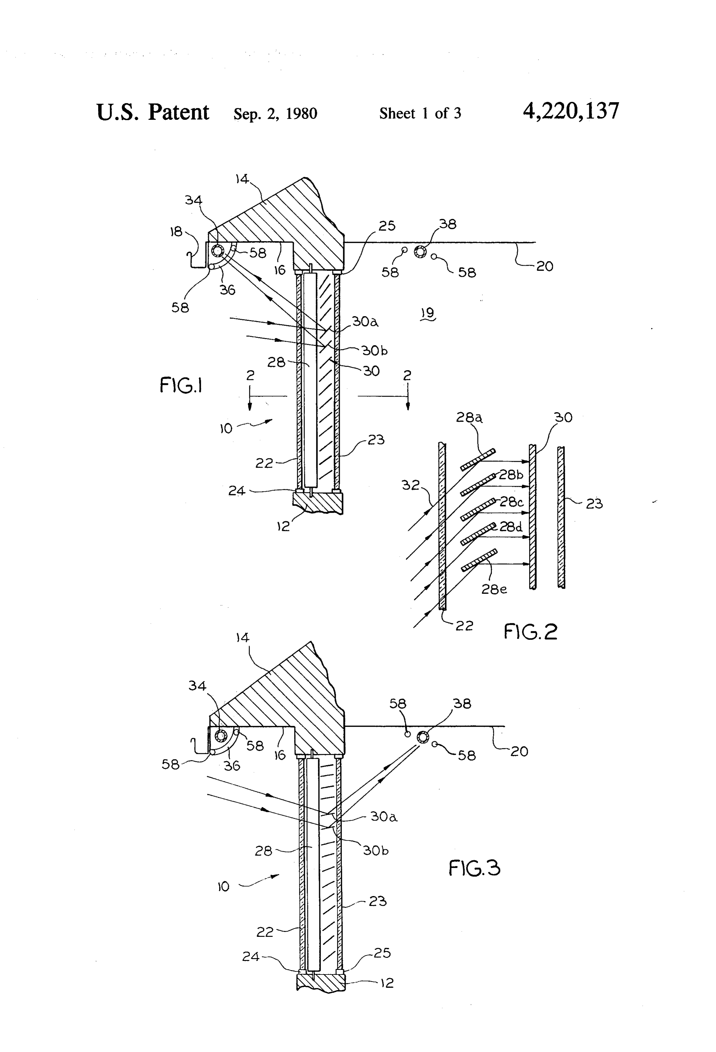
include problems relating to construction, e.g. due to Yet another object of the present invention is to pro large differences in internal temperatures, cracking of vide a solar energy collecting system which may be the glass and seals results and special chemicals have to used to reduce heat loss from structures. be used in chilly climates to prevent freeze-up of the A still further object of the present invention is to water passing through the collectors. provide a solar energy collecting system which includes It is also very difficult to add the presently available louvers and novel control means for focusing the sun's systems to existing buildings. Solar collector panels rays reflected from the louvers to an energy collector must be mounted in large numbers upon the roof of the and for automatically changing from one mode of oper building or on adjoining property. Still another disad 45 ation to alternate modes of operation depending on the vantage is that the systems perform no function during time of day or the amount of sunlight available. cloudy periods or at night. But probably the most im How these and other objects of the present invention portant problem with such systems is that they are effi are accomplished will be described in the following cient only when the sun reaches one particular location specification taken in conjunction with the FIGURES. relative to the collectors. 50 Generally, however, the objects are accomplished by Some known systems do include sun-tracking fea providing a solar energy collecting system which in tures. For example, in Wartes' U.S. Pat. No. 3,884,217 cludes at least one set of parallel louvers and control issued Sept. 20, 1972 for "Method and Apparatus for means for moving the louvers depending on the operat Collecting Solar Energy' a system is described which ing function desired. In the preferred embodiment of includes a plurality of flat, elongated reflector units. 55 the present invention, the louvers are designed to be The reflectors are arranged so that the beams of light inserted into a window opening so that the louvers are reflected therefrom to an energy collector. The replace normal window coverings, such as drapes, cur individual units are rotated about their horizontal axes tains, venetian blinds and the like. Preferably two sets of as the elevation of the sun changes, thereby maintaining louvers are mounted between a pair of parallel glass a convergence of the reflected rays. The unit described 60 plates. The outermost set of louvers is mounted verti in this patent also includes a drive unit for rotating all of cally, means being provided for controlling the angular the reflectors about the axis of the collector so that the orientation of the louvers from fully opened to fully reflectors always receive light at an angle normal to closed positions. When the louvers are fully closed, their axes. This equipment is quite bulky and does not solar rays impinging thereon from the outside is re overcome all of the aforementioned disadvantages. 65 flected away from the structure and an air space is cre Another type of system which has been developed ated between the louvers and the outermost glass panel includes a plurality of fixed lenses and means for mov to provide an insulation layer to reduce heat or cooling ing an absorber so that it always remains at the focal loss from the structure. When the first set of louvers is 6 opened, the louvers reflect sunlight interiorly and the Referring now to FIG. 1, a solar energy collecting control means generally directs sunlight inwardly at an system 10 is used for a building which includes a side angle that is perpendicular to the glass panes. This con wall 12, a roof 14 and eaves 16. The lower edge of roof trol system therefore, permits tracking for azimuthal 14 is laterally displaced from the side wall 12. A gutter changes in the sun position. It should also be noted that 18 is also shown in this FIGURE mounted to the lower the outside louvers can be fully opened to permit escape edge of roof 14. FIGS. 1 and 3 also show the building to of heat rays from the structure, for example, as might be include a room 19 inside of wall 12, the room 19 having desired on a warm summer evening. The second set of a ceiling 20 and, of course, other walls and a floor (not louvers is mounted inside of the first set, the inside shown).
louver members being mounted horizontally. Control 10 In this embodiment, solar energy collecting system 10 means are also provided for these louvers for moving is adapted for use as part of a window opening and is, them from fully opened to fully closed positions. These therefore, adaptable for use in existing houses, buildings louvers are adapted for catching the light rays reflected or in new construction. As a result, system 10 includes inwardly from the first set of louvers and directing them a pair of parallel and spaced apart glass panes 22 and 23, to an energy collector, for example, a pipe through 15 which in turn are mounted in a window opening by top which water is circulated. These louvers are controlled and bottom frame members 24 and 25. The side support so that the individual louver members track the sun to frames are not shown. Panes 22 and 23 should be trans maintain the reflected light on the collector and thereby parent to infra-red and visible radiation. Not shown in compensate for sun elevation. As is the case with the the FIGURES are the glazing components for the glass, first set of louvers, these louvers can be closed to form 20 but it should be understood that an air space is provided an additional air space or they can be opened com between panes 22 and 23, and, therefore, the panes pletely to permit heat rays to leave or enter the struc function like a conventional double glazed storm win ture. The present invention also provides a high degree dow. It should also be recognized, however, that sys of flexibility in the location of the collector. For exam tem 10 may be used with other types of window systems ple, the collector can be placed outside the structure for 25 such as double-hung, casement, etc. and that system 10 use during warm weather or it can be placed inside the can include screen members for permitting fresh air to building (or even between the sets of louvers) for cold enter the building and for permitting hot air to escape weather use. Various materials for constructing the from the building.
louvers are described in the specification, the preferred The primary components of the solar energy collect materials and shapes being those which improve the 30 ing system 10 are two sets of louvers 28 and 30 which heat reflecting and insulation properties of the louvers. are mounted between panes 22 and 23. For purposes of Several embodiments for the control system are also this description, individual louvers will be identified as described. 28a, 28b, 28c, etc. for the louvers of set 28 and 30a, 30b, DESCRIPTIONS OF THE FIGURES 30c, etc. for the louvers of set 30. Only certain of the 35 individual louvers will be specifically referred to so the
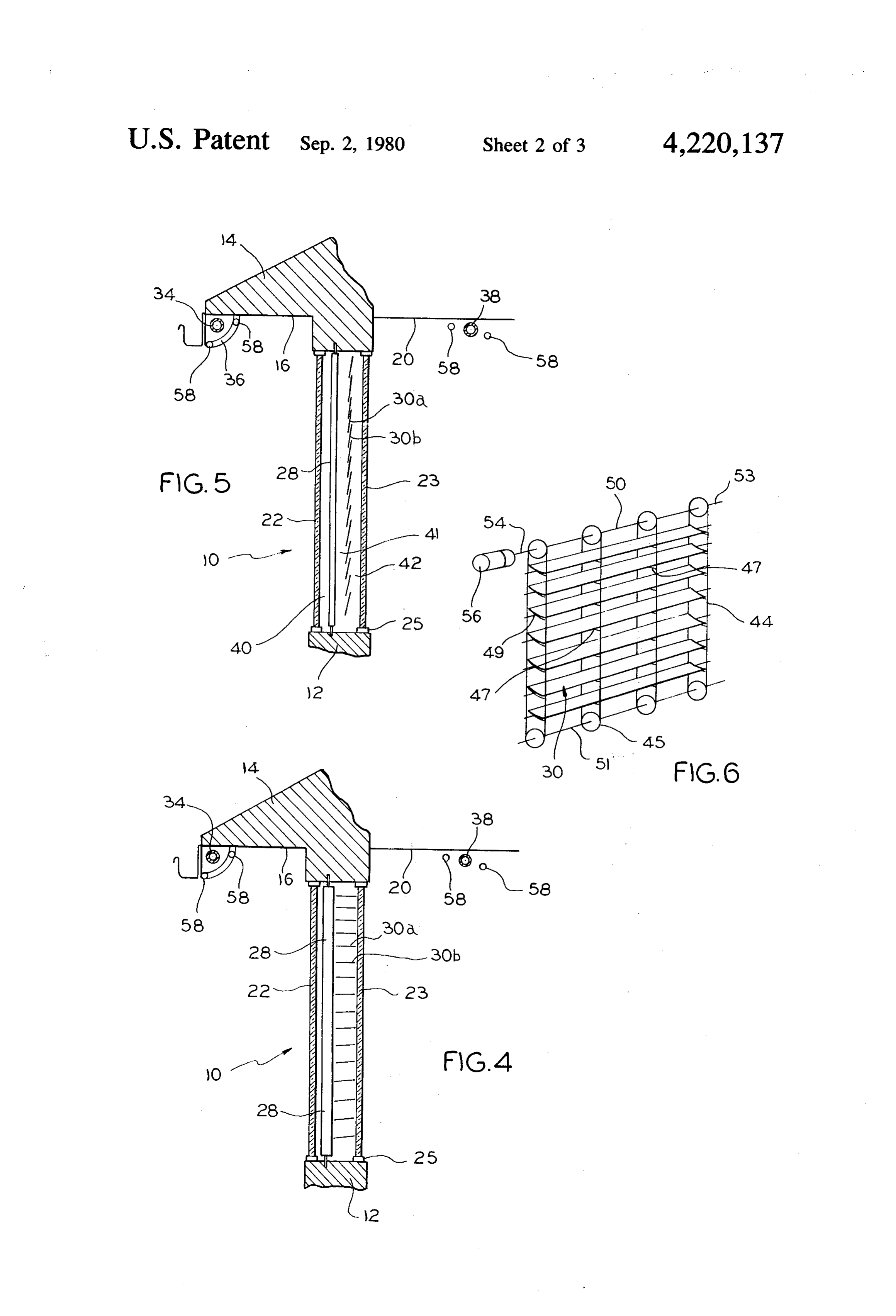
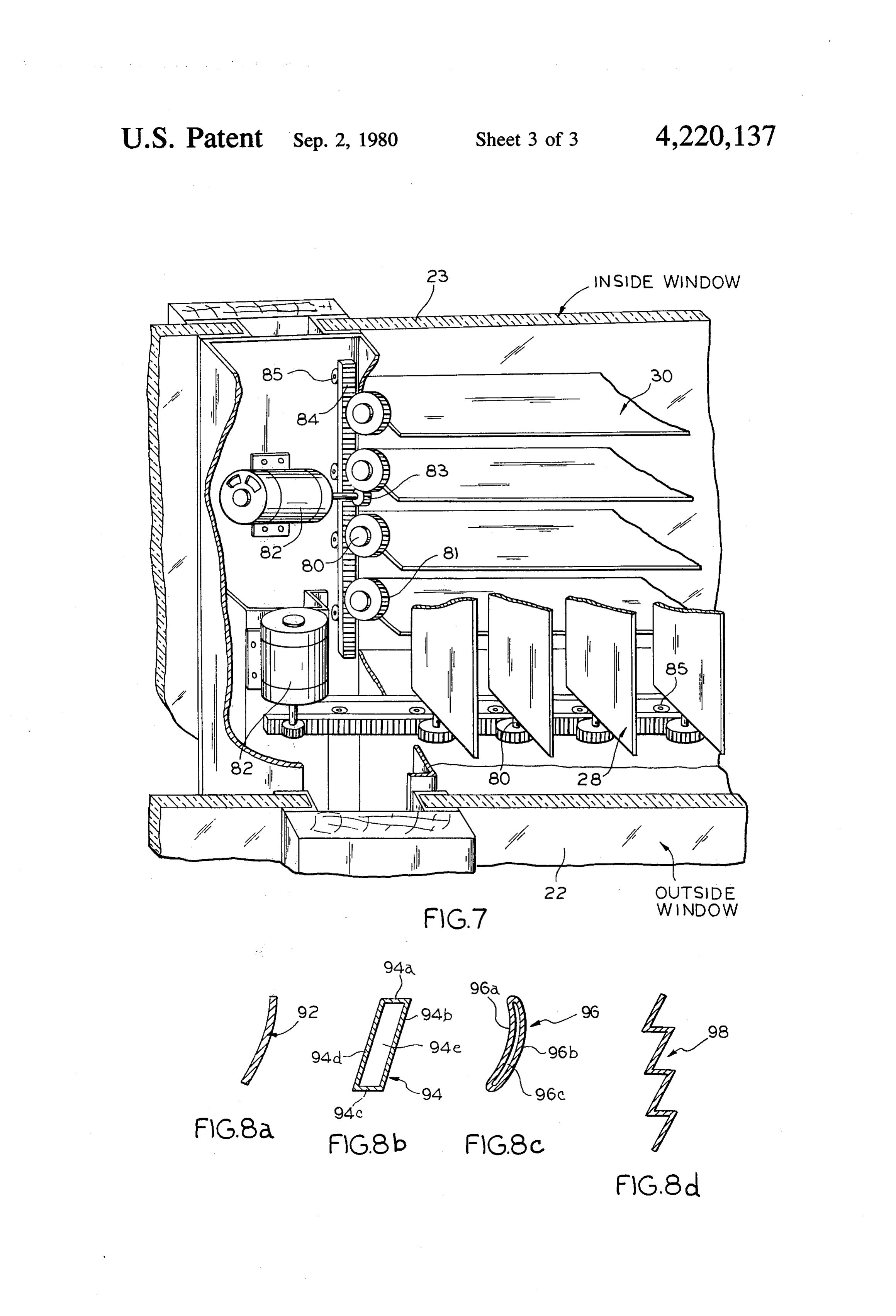
FIG. 1 is a cross-section showing one preferred form small reference letters are not meant to be limiting with of the present invention, the energy collector being respect to louver position, angle, etc. used on the outside of a building; Louvers 28 are mounted parallel to and just inside FIG. 2 is a partial section taken along the line 2-2 of pane 22 and are mounted vertically with respect to the FIG. 1; 40 building. Louvers 30 are mounted parallel to pane 23 FIG. 3 is a cross-section similar to FIG. 1 but show and are located between louvers 28 and pane 23, how ing the energy collector being used inside a building; ever, louvers 30 are mounted horizontally. Each indi FIG. 4 is a cross-section similar to FIG. 1, except vidual louver is pivotable about its axes and may be showing the louvers of the present invention in an oper moved for purposes advantageous to the objects of the ating mode which permits heat loss from a building; 45 present invention. It is also appropriate to point out at FIG. 5 is a cross-section similar to FIG. 1, except this time that the louvers are spaced from one another showing the louvers of the present invention arranged by a distance which will permit sets 28 and 30 to be fully for providing insulation to prevent heat or cooling loss closed if a high degree of insulation is required when from a building; system is not in use. In other words, each of the louvers FIG. 6 is a perspective view illustrating one form of 50 of set 28 may be adjusted to a position whereby the louver support and control system according to one widest dimensions of the louvers are parallel to pane 22. form of the invention; Similarly, each of the louvers of set 30 can also be FIG. 7 is a perspective view of an alternate form of moved so that the widest dimensions thereof face pane louver support and control system; and 23. The louvers can be oversized in width to permit FIGS. 8a-8d are cross-sections of louvers usable in 55 overlapping to insure a tight seal. The materials used for the present invention including curved, flat-insulating, louvers 28 and 30, the preferred shapes thereof and the curved-insulating reflectors and continuous, respec mechanism by which the louvers' position is set and tively. controlled will be more fully described in a later section DESCRIPTION OF THE PREFERRED of this specification.
EMBODIMENT Returning to FIG. 1 and FIG. 2, the function of the louver sets 28 and 30 can now be described. Louvers 28
The preferred embodiments of the present invention are for reflecting infra-red radiation from the sun will now be described by reference to the eleven FIG toward the inside of room 19, preferably in a line which URES, like reference numerals being used throughout. is perpendicular to panes 22 and 23. It will be appreci For the basic description, reference should be had to 65 ated that solar rays normally would enter the room at an FIGS. 1-5, these FIGURES illustrating the same em angle and depending on the orientation of the unit 10 bodiment of the invention in different operating modes with respect to the path of the travel of the sun, and the and different views. angle at which the sun moves through the sky, each of 7 louvers 28 will be moved at the proper angle for reflect heat reflective interior louvers 30 will reflect the inside ing solar rays toward room 19 as can be seen in FIG. 2. heat rays, preventing them from reaching the outside. It will also be apparent that the angle will vary from Alternately, and as shown in FIG. 4, during hot day to day as the path of the sun changes. For maximum weather both the vertical louvers 28 and the horizontal effectiveness, the louvers should also be as close as 5 louvers 30 may be placed in their fully opened positions possible to pane 22 for reflecting the maximum amount to allow heat rays from inside the building to radiate to of solar heat possible. FIG. 2 shows the operation of the outside. Again it should be mentioned that a screen five particular louvers 28a–28e in reflecting solar rays may be provided either in lieu of or in addition to panes 32 toward the louver set 30. 22 and/or 23, the panes being openable to permit fresh The function of the second set of louvers 30 can best 10 air to enter room 19 or heat to escape from room 19, as be appreciated by reference to FIGS. 1 and 3. These desired.
louvers are individually aligned for reflecting the sun Yet another operating mode can be carried out using light which reaches their surfaces to an energy collector system 10. In this embodiment, the first set of louvers 28 and, as was true of louvers 28, louvers 30 must also operates as was described in connction with FIGS. 1-3, compensate for movement of the sun. As seen in FIGS. 15 but the second set of louvers is adjusted to reflect solar 1-3, louvers 30 are each set at a different angle. How rays to a second predetermined location in room 19 ever, rather than correcting for azimuth position of the when sunlight is available and the room needs to be sun, these louvers compensate for zenith movement of heated. The predetermined location could be the floor, the sun and insure that the solar rays remains focused at a wall area or a heat sink located in the room. the desired location. 20 Still, a further operating mode which differs only The collector shown in FIG. 1 comprises a pipe 34 slightly from the foregoing would provide means for mounted outside of the room 19, below roof 14 and closing only the outside set of louvers 28 when, for behind the gutter 18. Pipe 34 is preferably about as long example, during a partly cloudy day the intensity of as horizontal louvers 30 and means (not shown) are impinging sunlight is insufficient to create the desired provided for passing water or some other suitable fluid 25 heat. In this mode, an air insulation space is created through pipe 34 for collecting heat therefrom. For ex between pane 22 and louvers 28, even though the fo ample, pipe 34 could be connected to a pump (not cused positions of louvers 30 are not affected. When shown) and other pipes could be provided for moving sufficient sunlight again becomes available, the ouside the fluid to means for storing and utilizing the heat set of louvers 28 is opened to the correct position. generated by system 10. The details of the heat collector 30 Dealing next with the louver control means of the system are not provided here because in and of itself it present invention, one form of such control for horizon forms no part of the present invention. However, by tal louvers 30 is illustrated in FIG. 6. The control sys way of illustration, pipe 34 can be a copper pipe. It can tem includes a plurality of endless loops 44 for support also be noted in FIG. 1 that the collector pipe 34 is ing louvers 30, the loops 44 each being held in place by surrounded by a glass shield 36 which is provided pri 35 a pair of wheels 45 located in the top and bottom frames marily to protect collector 34 from the weather. The of system 10. The loops 44 define a plane which is per glass shield 36 also serves to insulate collector 34 if the pendicular to panes 22 and 23 and include a plurality of exterior collector is used during winter operation of support strap members 47, preferably flexible supports, system 10. If the exterior collector 34 is used during between their respective sides. Louvers 30 in turn rest warm weather, the glass shield 36 need not be used 40 on the support members 47 so that they are held hori because insulation is not required. zontally in position. A sufficient number of loops 44 However, the present invention, in its preferred form, should be provided to insure sufficient support for lou includes a separate collector 38 for use in winter vers 30 and prevent sagging thereof.
months. Collector 38 is mounted on the ceiling 20 of It can also be seen in FIG. 6 that a pair of rods 50 and room 19 at a location which permits heat rays to be 45 51 are provided for supporting and turning wheels 45. reflected thereupon, such as is shown in FIG. 3. A glass The rods are parallel to one another, rod 51 being covering is not required because heat losses are to the mounted in the bottom of the window frame for free structure itself and there is no need to protect the col rotation. Each of the bottom wheels 45 is securely af. lector 38 from evening cool-down. The fluid supply, fixed to rod 51 so that movement of the rod will cause pumps and heat storage systems for collector 38 may be 50 simultaneous rotation of all of the wheels. To insure that the same as those employed for collector 34, suitable rod rotation results in uniform movement of the lou valving being provided for permitting a switch-over vers, a non-slip material or coating is preferably added from one collector system to the other. The advantages to the periphery of the wheels 45 or to the inside of of the dual collector system become apparent when it is loops 44, or to both.
understood that the heat rays focused on the collectors 55 The upper rod 50 includes a first end 53 which is heat the collectors and, naturally, the surrounding envi supported for free rotation in the upper window frame ronment. The use of an exterior collector in the summer but the other end 54 of rod 50 is coupled to a motor 56 will avoid creation of undesirable heat in room 19, which is adapted for controlled rotation of rod 50 in while the use of an interior collector during the winter either direction about its axis. As was the case with rod months will result in heat being generated not only to 60 51, the upper wheels 45 are affixed to rod 50 (preferably the collector but to the room also. with a non-slip covering) and the loops 44 pass over the The solar energy collector system 10 illustrated in aligned wheels and are held taught therebetween. FIGS. 1-3 may also be used for several other operating From the FIGURES, especially FIGS. 1 and 3 it can functions. For example, as illustrated in FIG. 5, the be seen that the angle of individual louvers 30 varies louvers may each be placed in their closed position 65 from the uppermost louver to the bottom louvers and which will create three air spaces 40, 41 and 42 between the spacing between the louvers also increase from the the two glass panes 22 and 23. In addition to the insula top to the bottom louvers. Because the solar rays reach tion provided in this operating mode of system 10, the the inside set of louvers at a common angle and because 8 the inside set of louvers 30 reflects the heat rays to a While the preciously described form of support and common and relatively small area, the louvers 30 will control for adapting this system to existing windows is have to be individually focused to the collector in order illustrated as resembling a venetian blind arrangement to achieve maximum temperatures. other types of controls may also be used. For example In the illustrated embodiment each of the louvers is and as shown in FIG.7 each of louvers 30 and 28 may initially set between the sides of loops 44 by properly be mounted in a rigid frame. Pins 80 which are provided affixing the two ends of support members 47 at a proper at both ends of the louvers are received in parallel and angle with respect to one another. The angle will vary aligned holes on opposite sides of the frame and each for each support member 47 as indicated in the preced pin is fixed to a gear 81 inside the frame. Motors 82 in ing paragraph. When the louvers 30 are placed in the 10 the embodiment would be coupled to one louver gear loops on supports 47, all of the louvers will be rotated directly or by using a gear 83. The gears of all the lou about their axes in the same direction when rods 50 and vers would be coupled by a gear rack 84 allowing all 51 are rotated. During the sun's movement, louvers 30 louvers to change their position by motor 82 when will rotate axially to maintain their specular reflection called for. A belt and pulley arrangement could also be to the line of concentration at the collector. As is also 15 used. Louvers 30 in this embodiment, or in any of the apparent from FIGS. 1 and 3, different initial louver others just described, could be mounted under tension alignments are required when collector 34 is being uti to aid in maintaining the intergrity of the louvers. The lized from those where collector 38 is being used. It frame embodiment also provides an additional advan should also be mentioned here that instead of the bot tage in that the frame can be slanted or swing toward tom wheels 45 and rod 51, a weighted bar can be used 20 the inside of room 19 for cleaning. Of course, to do this to permit the entire set of louvers 30 to be raised out of pane 23 would have to be made part of the frame, or the way when not in use, similar to a venetian blind. would have to be removed prior to louver cleaning. As indicated previously, the motor 56 is designed for The embodiment shown in FIG. 7 also permit the use of rotating rod 51 to maintain the correct louver position the same motor containing chamber for adjacent sets of and has the capability of rotation in both directions to 25 window louvers.
accomodate the various operating modes envisioned by Motor 82 and its associated louver control means the present invention. Motor 56 is preferably an electro could also be coupled to the sun sensing photocells mechanical motor which acts in response to a signal referred to earlier for totally opening or totally closing which in turn is generated by manual or automatic sen louvers 28 for the operating modes previously de sors, a variety of types of which may be used in the 30 scribed. For example, during periods when sunlight is present invention. insufficient to utilize the energy collecting mode of One example of a suitable sensor is a combination FIGS. 1-3, the insulation, heat radiation or other modes solar intensity sensor and timer. Other examples are can be employed.
temperature sensors, manual controls, and twenty-four The final components of the solar energy collecting hour indexing timers. A description will be provided for 35 system 10 to be described are the louvers themselves, the solar intensity sensor system, it being understood which as shown in FIGS. 8a, 8b, 8c and 8d may take a that the other systems could be readily adapted by one number of forms. These FIGURES are all cross sec skilled in the art. tions of various louvers which are preferred for use in The intensity sensor system consists of a pair of pho the present invention. All louvers are preferably con tocells 58 located on either side of collector 34 (or 38) structed of metal or plastic with a speculative reflective adapted to act as limit switches for controlling louvers surface and the desired structure strength. 30. When light is focused on either of the cells, the Louvers 28 which reflect the solar rays towards the sensor system would react to activate motor 56 to cause louvers 30 could be coated or laminated with a light-fil the focused solar rays to shift in the proper direction, tering material to minimize light reflection into room 19 i.e. back onto collector 34 (or 38). Instead of the photo 45 if this condition would be undesirable. This coating cells 58, temperature sensitive sensors on either side of would not be required on louvers 30 because the loca collector 34 could perform the same function. Another tion of their focal line is at the collector 38. Louvers 30 pair of photocells (not shown) located at the ends of could be a highly polished material such as bright alu collector 34 would control louvers 28 in the same man minum.
e SOAnother feature of the present invention permits Photocells (not shown) unassociated with the collec louvers to be constructed from materials which are tors can also be employed as part of the louver control transparent to visable light while being reflective to system for moving the louvers to various other operat infra-red radiation. This type of material is commonly ing positions. For example, a photocell located adjacent laminated to glass windows and also used as window the window opening could sense when insufficient light 55 shades to reflect heat away from buildings. is being received. For example, at night or on cloudy The size of the louvers is limited, only to where they days, or even when the sun passes behind a cloud during will be used (height, width, and depth of window area). an otherwise sunny period, such a photocell activates Of course, the single strength louvers 92 of FIG. 8a can the motor 56 to place the louvers in the insulation mode be flat rather than curved, but the curved form permits shown in FIG. 5, the heat release mode shown in FIG. greater concentration of solar rays to a fixed line and 4 or in any of the other positions described herein. A far increases the bending strength of the louvers. more simple type of louver control would comprise a FIG. 8b illustrates a second preferred form for lou simple timer adapted for rotating the louvers at a con vers 28 and/or 30. This form is the insulating flat louver stant speed or indexing them during the period of the 94 which is generally trapezoidal in cross section. Lou day when sunlight impinges on system 10. Of course, 65 ver 94 has 4 sides 94a, b, c, and d, a hollow center 94e such a timer sould have to be adjusted periodically to and ends (not shown). As with louver 92, louver 94 compensate for changes in sun position and the period should have the desired solar reflecting properties and of daylight. may also be transparent to visible radiation.
Page 9scan →
This second form of louver is especially beneficial for very long useful life and is not subject to the weathering use in systems where maximum insulation is required problems so common with other systems known to the during periods when sunlight is not present, and it will art. .. ' '.
be appreciated that the air within louver 94 creates an While the present invention has been described in insulating air space while the trapezoidal shape allows connection with the illustrated preferred embodiments, each louver to form an effective seal between the lou those skilled in the art to which this invention is di vers and pane 22. It should also be appreciated that rected would be able to construct other embodiments louvers 94 can be formed of solid materials such as incorporating the louver principle of the invention. For expanded polystyrene with a suitable infra-red reflec example, for some embodiments it may be possible to tive coating. 10 eliminate louvers 28, e.g. where the building in which A third form of louver is shown in FIG.8c, this form the system is to be used has rooms large enough to 96 being curved in cross-section and including curved house large or very long collectors. The efficiency and inner and outer surface 96a and b respectively and hol cost of such a modification is not however as practical low center 96c. Louver 96 may be formed by extrusion as the double louver system described above. More or other suitable manufacturing techniques and should 15 over, while the louvers have been illustrated as being have sealed ends (not shown) for creating an insulating pivotable about their axes, movement about an edge is dead airspace within the louver. This form of louver also within the scope of the invention. Yet other modifi may also be constructed of a solid piece of insulating cations in the provision of a collector which converts material (with suitable solar reflecting coatings), trans solar energy directly into electrical energy. Accord parent materials to provide viewing through unit 10 or ingly, the invention is not to be limited to the illustrated from other materials known to the art. The double embodiment but is to limited solely by the claims which strength louvers of FIGS. 8b and 8c also provide an follow.
increased bending strength as well as the more obvious We claim:
insulation valves because of the overlapping ability. 1. A solar energy collecting system comprising two Other louver shapes may be used in the present inven 25 sets of solar ray reflective louvers installed in a window tion, and the present invention is not meant to be limited opening of a building, a first set of said louvers being by the illustrated preferred louvers 92, 94 and 96. mounted vertically and the second set of said louvers FIG. 8d illustrates another preferred form for louvers being mounted horizontally, a solar energy collector 30. This form 98 would be molded or formed such that located generally adjacent but spaced apart from said the louvers would be permanently shaped into a zig-zag 30 window opening, control means for moving said lou shape sheet and have a common focal line for all formed vers to compensate for changes in sun position and louvers. These louvers can not rotate to compensate for resulting changes in the incident angle at which solar changes in the suns elevation, therefor the collector rays impinge upon said louvers, one set of said louvers would have to be larger or it would have to move to being arranged and controlled by said control means for stay on the focal line. This single sheet of louvers could 35 reflecting incident solar rays to said other set of louvers, easily be placed between two sheets of glass thus form and said other set of louvers being arranged and con ing a double insulated window which would be less trolled by said control means for reflecting and focusing than 1 inch thick. Also this sheet could replace one solar rays reflected thereon to said solar energy collec pane of glass. to.
The solar energy collecting system 10 of the present 40 2. The invention set forth in claim 1 wherein said invention offers many advantages which can be briefly collector is located exteriorly of said building. summarized. System 10 can be utilized in windows of 3. The invention set forth in claim 1 wherein said new or existing rooms and still permit sunlight to enter collector is located interiorly of said building. the room. The system is mounted in a permanently 4. The invention set forth in claim 1 wherein a collec located frame so frame rotation for tracking the sun is 45 tor is located exteriorly of said building and another not necessary. The system can be used for focusing collector is located interiorly of said building, said con radiation alternately to collectors located inside or out trol means being adapted for selectively reflecting solar side of the building and the system neither decreases rays to one or the other of said collectors. usable space in the building nor diminishes the aesthetic 5. The invention set forth in claim 1 wherein said value of the structure. 50 vertically mounted louvers reflect light to said horizon Other important advantages include the elimination tally mounted louvers, said vertical louvers being of multiple collectors (the present system requiring only mounted exteriorly of said horizontal louvers in said a single collector pipe through which a suitable gas or window opening.
liquid is forced), no special glazing is required, cleaning 6. The invention set forth in claim 1 wherin said lou is minimized and easy, window coverings can be elimi 55 vers are mounted intermediate a pair of parallel and nated, room heating as well as collector heating can be spaced apart glass panes, said panes being transparent to carried out, the components of the system do not re visible and solar heat radiation.
quire any special insulation and at the same time the 7. The invention set forth in claim 1 further including system itself can provide extremely beneficial insulation means for fully closing said louvers. properties to the structure. 60 8. The invention set forth in claim 1 wherein at least Accordingly, the objects of this invention are accom one set of louvers is comprised of curved louvers. plished by providing a system which not only effi 9. The invention set forth in claim 1 wherein at least ciently captures usable infra-red radiation from the sun, one set of said louvers is constructed of heat insulating but does so utilizing equipment which is relatively sim material whereby when said louvers are fully closed, ple to construct, relatively inexpensive to manufacture 65 the insulation of said window opening is improved. and which provides so many additional advantages that 10. The invention set forth in claim 1 wherein said the cost of initial installation is further reduced. The louvers are transparent to visible radiation. energy collecting system of the present invention has a 11. A solar energy collecting system comprising:
Page 10scan →
a first set of louvers mounted vertically, each of said set of louvers remain focused on said collector regard louvers being pivotable about its axis and a first less of sun position.
control means being provided for said first set of 15. The invention set forth in either of claims 11 or 14 louvers for uniformly pivoting individual louver wherein said control means is adapted for fully opening members from fully opened to fully closed posi 5 and fully closing at least one set of said louvers. tions and for tracking sun position; 16. The invention set forth in claim 13 wherein each a second set of louvers mounted generally adjacent to of said louver means includes gear means, said gear said first set of louvers, said second set of louvers means being coupled to a rack gear means provided for being mounted horizontally;
said first set of louvers being arranged for reflecting 10 each motor of said first and second set of louvers and said means being coupled to said rack gear means for solar rays toward said second set of louvers;
an elongate solar energy collector located generally sliding 17. A same and rotating said louvers about their axes.
solar energy collecting system comprising a adjacent to and parallel to said second set of lou plurality of elongate, generally parallel louvers installed vers;
each of said second louvers being arranged for reflec 15 in a window opening of a building, each of said louvers tin solar rays from said first louvers toward said solarhaving a solar ray reflective surface, a pair of elongate energy collector; and energy collectors spaced apart from said window second control means for said second set of louvers to opening and offset therefrom, whereby said collectors uniformly rotate same about their axis to track sun are generally parallel to each of said louvers but do not position and maintain the solar rays reflected there 20 intersect any line which is perpendicular to the surface from focused on said collector. defined by said window opening, one of said collectors 12. The invention set forth in claim 11 wherein said being located exteriorly of said building and the other of two sets of louvers are mounted in a window opening of said collectors being located interiorly of said building, a building. control means for moving said louvers to compensate 13. The invention set forth in claim 11 wherein said 25 for changes in sun position and resulting changes in the control means include motor means for rotating said incident angle at which solar rays impinge upon said louvers about their axis. louvers, said louvers being arranged for focusing said 14. The invention set forth in claim 13 wherein said solar rays onto one or the other of said collectors, and control means further includes solar ray sensor means whereby said system includes a control means being coupled to said motor means for insuring that said first 30 adapted for selectively reflecting solar rays to one or louvers reflect solar rays toward said second set of the other of said collectors.
louvers and that solar rays reflected from said second . . . . . .
Provenance
- Collection
- Patents citing this work
- Pages
- 10
- Method
- pdftotext (the PDF's own text layer) + pdftoppm 300dpi page scans
- Patent office record
- patents.google.com →
- Source
- Google Patents citing-documents table
- Assignee
- Tesch Allen R
- Published
- 1980-09-02
- Transcribed from
- patentimages.storage.googleapis.com →