

patent · US4224925A
Heating system
30 September 1980
Text
Page 1bibliographic recordscan →
United States Patent (19)
Movick
(54) HEATING SYSTEM
(76) Inventor: Nyle O. Movick, 4600 Macky Way,
Boulder, Colo. 80302
Int. Cl’.............................................. F24D 11/00 52 U.S. C. .................................... 126/427; 417/118;
524,718 8/1894 Jencks et al. ......................... 417/118 2,932,287 4/1960 Goetz .............. . 417/126 4,050,445 9/1977 Huse ..................................... 126/271 4,061,131 12/1977 Bohanon ..... ... 237/1 AX 4,111,189 9/1978 Dizon ............................... 165/104 S 4,120,289 10/1978 Bottum ... ... 237/1 AX 4,131,231 12/1978 Cleer ............................... 237/1 AX Primary Examiner-Ronald C. Capossela
Assistant Examiner-Henry Bennett
SYSTEM
Attorney, Agent, or Firm-Stephen A. Gratton
A heating system for heating a building or the like wherein a working fluid is heated by heat sources such as fireplace heat collectors or solar heat collectors is vaporized, and then circulated in a closed loop to a lower level of the building where the heat is extracted by condensing the vapor back to a liquid. The extracted heat is stored at the lower level of the building in a storage tank and can then be easily distributed through out the building as required for heating the building. A closed circulating loop for the working fluid keeps the heated vaporized working fluid circulating from the heat collectors down to the heat storage tank for con densation and the condensed liquid working fluid circu lating from the storage tank up to the heat collectors for reheating. The circulating loop utilizes gravity and the pressure generated by vaporizing the working fluid to move the working fluid through the system without external pumps or controls and with no additional en ergy input.
13 Claims, 3 Drawing Figures
SCHEMATIC
Drawings
Page 2drawing sheetscan →
Page 3drawing sheetscan →
Page 4scan →
ventional heat exchangers and natural thermal circula
The heat collectors are adapted to contain the work
FIELD OF THE INVENTION ing fluid and to provide the heat input for boiling the The present invention relates to heating systems and 5 working fluid. The working fluid is preferrably a refrig more particularly to a new and improved system for erant such as one of the refrigerants in the "Freon' heating a building wherein a working fluid is heated by familyatmanufactured by the DuPont Company, that will a heat source such as a fireplace or solar collector and boil different pressures over a wide temperature then circulated to a lower level of the building where O isrange. The vapor produced by boiling the working fluid circulated in a closed loop to a heat exchanger sub the heat is extracted for storage and distribution.
mersed in a heat storage liquid within the heat storage
BACKGROUND OF THE INVENTION tank. When the temperature of the heat storage liquid is Heating systems in which a fluid is heated and then below the condensation temperature of the working fluid the vaporized working fluid is condensed in the thermally circulated through a closed loop to other 15 heat parts of the building are well known in the prior art. izationexchangerof the back to a liquid and the heat or vapor working fluid is extracted into the storage
Generally such systems utilize a heat source such as a liquid. A heat distribution system then extracts the heat boiler that is located at a lower level of the building to from the storage liquid and distributes it throughout the heat a medium such as water for circulation through the building utilizing natural thermal circulation. loop. In systems of this type thermal circulation is gen 20 The closed circulating loop functions to maintain the erally utilized to circulate the heating medium with the heat laden vaporized working fluid produced by the relatively low density heated water and steam rising to heat collectors circulating into the heat exchanger for the upper portions of the building where the heat can be heat extraction into the storage liquid and also maintains extracted, and the relatively high density condensate the cooled and condensed working fluid exiting from flowing by gravity back to the lower level heat source 25 the heat exchanger circulating back to the heat collec for reheating.
A limitation with such heating systems is that to uti comprises a lowerThe tors for reheating. closed circulating loop generally lize thermal circulation to distribute the heat, the heat distributing reservoir connectedreservoir collecting to each and an upper other and other sources must always be located at the lower portions of components of the system by sealed conduits. The the building. Some heat sources such as solar collectors 30 lower collecting reservoir is a sealed vessel located or fireplace collectors generally cannot be located at the lowest levels of the building and therefore require below the heat collectors and heat storage tank and additional mechanical apparatus such as pumps or tor alongvaporized collects with working fluid from each heat collec condensed working fluid from the heat blowers to transfer the collected heat from their level to exchanger. The lower collecting reservoir is pressur lower levels of the building where the heat can be used 35 ized by the accumulation of the vaporized working fluid or stored. The use of pumps and blowers in systems of and the pressure forces the mixture of vaporized and this type not only expends considerable energy but also condensed working fluid upward to the upper distribut requires expensive equipment and controls. ing reservoir that is also sealed, where the vapor and Accordingly, it is an object of the present invention condensate to provide a heating system in which heat is circulated 40 reservoir thearevapor separated. From the upper distributing is directed by gravity through con from an elevated level of a building to a lower level for duits to the heat exchanger in the storage tank for heat storage and distribution without additional energy or extraction and the condensate is directed by gravity output. through conduits to the heat collectors for reheating. Another object of the invention is to tie multiple heat The arrangement is such that as the temperature of collectors such as solar collectors and fireplace collec 45 the storage liquid rises with heat input from the work tors into one integrated system that requires no external ing fluid the pressure in the system also rises so that the pumps or energy to move the collected heat to other working fluid boils and condenses at higher tempera parts of the building. tures. Thus over the operating range of the system the Yet another object of the invention is to provide a pressure is varied so that the working fluid will always novel heating system wherein heat is collected and 50 condense at a temperature below the temperature of the transferred to a lower level storage tank whenever the storage liquid and the heat input into the system will in input temperature of the heat collectors is slightly effect follow the temperature of the storage liquid. higher than the storage tank temperature and wherein Other objects, advantages and capabilities of the pres heat input into the system will follow the storage tank ent invention will become more apparent as the descrip temperature. 55 tion proceeds taken in conjunction with the accompa SUMMARY OF THE INVENTION nying drawing in which like parts have similar refer ence numerals and in which;
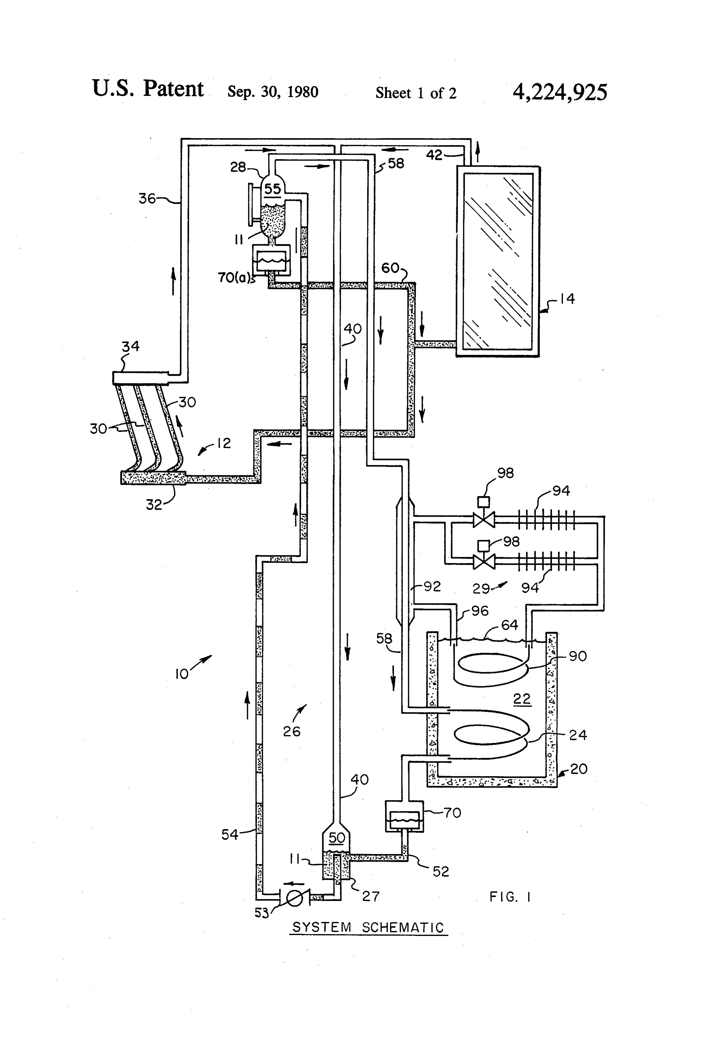
A heating system for heating buildings or the like FIG. 1 is a diagrammatic side elevation view of the wherein a liquid working fluid is heated by various heat heating system of the invention;
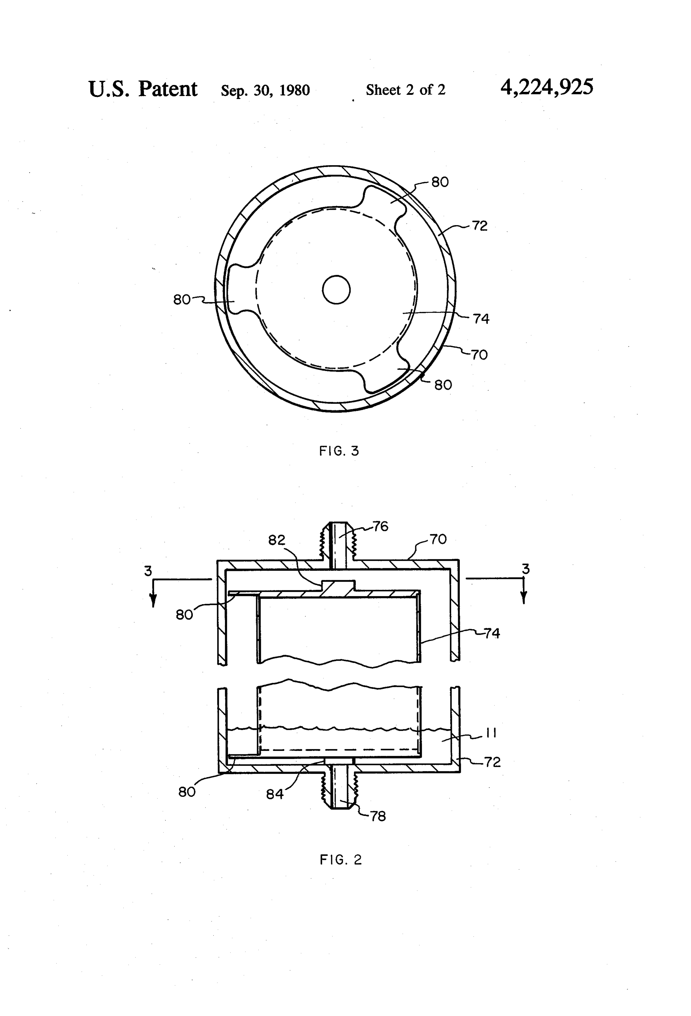
sources such as fireplace heat collectors and solar col FIG. 2 is an enlarged cross sectional view of a liquid lectors to transform the liquid to a vapor. The heat separator component of the invention; and laden vaporized working fluid is then circulated to a FIG. 3 is section 3-3 of FIG. 2. heat storage tank at a lower level of the building where the heat is extracted by condensing the vapor back to a DETAIL DESCRIPTION OF THE INVENTION liquid. The condensed liquid is then circulated back 65 Referring now to FIG. 1 an illustrative embodiment through the collectors for reheating. From the lower of the heating system of the invention designated as 10, level heat storage tank the extracted heat can then be is shown and generally stated comprises; a working easily distributed throughout the building utilizing con fluid 11 illustrated in its liquid form in the drawings as 5 shaded and in its vapor form as clear; a fireplace heat vaporized working fluid formed in the solar collector 14 collector 12 and a solar heat collector 14 for heating and may flow from the collector into the lower collecting vaporizing the working fluid 11; a heat storage tank 20 reservoir 27.
located at a lower level of the building filled with a heat Circulating Loop storage liquid 22 for extracting heat from the working fluid 11 for storage; a heat exchanger 24 submersed in The circulating loop 26 generally comprises the the storage liquid 22 for transferring heat from heated lower collecting reservoir 27 and the upper distributing vaporized working fluid 11 to the storage liquid 22; a reservoir 28 and various conduits that connect the closed circulating loop generally designated 26 having a lower collecting reservoir 27 and upper distributing lower collecting reservoir 27 and an upper distributing 10 reservoir 28 to other components of the system. The reservoir 28 for circulating vaporized working fluid 11 function of the circulating loop 26 is to circulate vapor from the heat collectors 12, 14 through the heat ex ized working fluid 11 into the heat exchanger 24 for changer 24 for heat extraction, and liquid working fluid heat extraction and liquid working fluid 11 into the from the heat exchanger 24 back through the collectors fireplace 12 and solar 14 heat collectors for heating and 12, 14 for heating; and finally a heat distribution system 15 29 for extracting heat from the heat storage liquid for vaporizing.
The lower collecting reservoir 27 is a sealed vessel distribution to the building. having a pressure tight inner chamber 50 and is coupled Working Fluid at its upper end to vapor conduit 40 for receiving vapor ized working fluid 11 from the fireplace 12 and solar 14
The working fluid 11 can be any stable, noncorrosive, 20 heat nontoxic substance that has a suitable liquid vapor phase collectors. The inner chamber 50 is also coupled to serve satisfactorily in the temperature range required. near its lower end to a conduit 52 from the heat ex It is desirable to utilize a working fluid 11 that will boil changer 24 for receiving liquid working fluid 11 from at different pressures over almost the entire temperature the heat exchanger 24. In addition a lower collecting range expected at the storage tank 20 so that any heat 25 reservoir discharge conduit 54 extends a distance into input in vaporizing the working fluid can be extracted the interior of the chamber 50 for discharging liquid and by the heat storage liquid 22 in condensing the vapor vaporized working fluid 11 from the lower collecting back to a liquid as will hereinafter be explained. If water reservoir 27 to the upper distributor reservoir 28. A is used as a heat storage liquid 22 for example its liquid check valve 55 is coupled to discharge conduit 54 such temperature range is 32 F. to 212 and it is desirable to 30 that the working fluid may flow from the lower collect have a working fluid 11 that will boil at different pres ing reservoir 27 to the upper distributing reservoir 28 sures over nearly this whole range. Certain Freons but cannot flow in the opposite direction from the upper manufactured by E. I. DuPont de Nemours and Com distributing reservoir 28 to the lower collecting reser pany will satisfy these requires for a working fluid. For voir 27.
instance "Freon' sold under the trade name of "Gene 35 The upper distributor reservoir 28 is a sealed vessel tron #11' has a boiling point of 74.7 at atmospheric having a sealed inner chamber 55 and is located at a pressure and would work satisfactorily in this applica substantial height above the lower collecting reservoir tion. 27 and heat collectors 12, 14. The upper distributing Heat Collectors reservoir 28 receives vaporized and liquid working fluid from the lower collecting reservoir 27 and distributes
The fireplace heat collector 12 is a grid type device is the liquid working fluid by gravity to the heat collec designed to fit in the hearth of a conventional fireplace tors 12, 14 for heating and the vaporized working fluid and transfer heat from burning logs in the fireplace to by gravity to the heat exchanger 24 for heat extraction. the working fluid 11. The fireplace collector 12 com The discharge conduit 54 from the lower collecting prises a plurality of curved spaced parallel pipes 30 45 reservoir 27 is coupled to the interior chamber 55 of the adapted to contain the working fluid 11 connected to a upper distributing reservoir 28 near the top of the reser lower level manifold 32 and an upper level manifold voir 28. To move the working fluid 11 from the lower pipe 34. This arrangement forms a grid for partially collecting reservoir 27 through the discharge conduit surrounding any open flames produced by burning logs 54 into the upper distributing reservoir 28 pressure must in the fireplace. Heat can thus be collected from the 50 be built up in chamber 50 of the lower collecting reser flames and transferred through the pipes 30, 32, 34 to voir 27 by the vaporized working fluid entering the the working fluid 11 for boiling the working fluid.
The upper manifold pipe 34 of the fireplace heat chamber.to Once the pressure in chamber 50 is high collector 12 is coupled to a vapor conduit 36 which enough overcome the height differential between the extends upwardly from the fireplace heat collector. 55 lower collecting reservoir 27 and the upper distributing Vapor conduit 36 is coupled to another conduit 40 reservoir 28 vaporized and liquid working fluid 11 will which extends downwardly to the lower collecting move as shown in FIG. 1 from the lower collecting reservoir 27. Vaporized working fluid formed in the reservoir, through discharge pipe 54 to the upper dis fireplace heat collector may thus flow upward through tributing reservoir 28.
conduit 36 and downward through conduit 40 to the At the upper distributing reservoir 28 the liquid and lower collecting reservoir 27. vaporized working fluid 11 are separated. A vapor sup The solar collector 14 is a conventional solar collec ply conduit 58 is coupled to the upper distributing reser tor panel that is also adapted to contain the working voir 28 near the top of chamber 55 for directing vapor fluid 11 and transfer heat to the working fluid for vapor ized working fluid to the heat exchanger 24. A liquid izing the fluid. The outlet of the solar collector 14 is 65 supply conduit 60 is coupled to the upper distributing coupled to a vapor conduit 42 which extends upwardly reservoir 28 near the lower end of chamber 55 for di from the solar collector 14. Vapor conduit 42 is also recting liquid working fluid 11 through the fireplace 12 coupled to downwardly extending conduit 40 so that and solar 14 heat collectors for reheating.
Page 6scan →
Heat Storage Tank and Heat Exchanger the liquid separator 70 to the lower collecting reservoir 27 is sealed by tip portion 84 of the float member 74.
The heat storage tank 20 is located below the heat The float member 74 will remain in this position until collectors 12, 14 and upper distributing reservoir 28. In enough liquid working fluid accumulates at the bottom most buildings the heat storage tank 20 may be conve of the enclosure 72 to overcome the downward gravita niently located in the basement of the structure or bur tional and pressure forces acting on the float member 74 ied in the ground adjacent to the structure. The heat and buoy the float member 74 upward sealing opening storage tank 20 comprises a vessel such as a concrete 76 with tip portion 82 and allowing the liquid working tank vented to atmosphere that is large enough to hold fluid to flow through opening 78 to the liquid separator a sufficient volume of the heat storage liquid 22 to store O 70. When the level of the working fluid 11 drops again a useable quantity of heat. As shown in FIG. 1 the heat the float member 74 again moves to the closed position storage tank 20 is filled with the heat storage liquid 22 to and seals opening 78 until the liquid level once again the level indicated by wavy line 64. The heat storage rises and the cycle is repeated.
liquid 22 may be water or any other stable nontoxic Thus the liquid separator 70 allows only condensed liquid capable of heat storage. 15 liquid working fluid to exit from the heat exchanger 24. The heat exchanger 24 is a length of coiled tubing If the temperature of the storage liquid 22 is above the submerged within the heat storage liquid 22 near the condensation temperature of the working fluid at the bottom of the heat storage tank 20. The heat exchanger system pressure, vaporized working fluid will accumu 24 is coupled at one end to the vapor supply conduit 58 late in the heat exchanger 24 until the pressure of the from the upper distributing reservoir and at the other 20 system raises and the condensation temperature of the end to conduit 52 to the lower collecting reservoir 27. working fluid raises. When the condensation tempera When the temperature of the storage liquid is lower ture exceeds the temperature of the storage liquid 22, than the temperature of the heated vaporized working the working fluid can condense in the heat exchanger 24 fluid 11 in the heat exchanger 24 heat will flow from the and the liquid separator will cycle allowing the liquid to working fluid 11 into the storage liquid 22. If the pres 25 exit from the heat exchanger 20 into the lower collect sure in the system is such that the condensation temper ing reservoir 27.
ature of the working fluid 11 is above the temperature A second liquid gas separator 700a) identical in con of the storage liquid 22 the vaporized working fluid 11 struction to the previously described liquid gas separa will readily condense in the heat exchanger 20 back to tor is coupled to conduit 60 near the liquid discharge a liquid giving up its heat of vaporization to the storage 30 end of the upper distributing reservoir 28. Liquid sepa 22. A liquid separator coupled to the discharge of the rator 700a) allows only liquid working fluid to exit from heat exchanger 24 as will hereinafter be explained pre the upper distributing reservoir 28 through conduit 60 vents vaporized working fluid from exiting from the to the heat collectors 12, 14 for reheating. heat exchanger 24 until it has condensed back to a liq Heat Distribution System uid. If the pressure in the system is such that the temper 35 ature of the storage liquid 22 is higher than the conden Referring to FIG. 1 the heat distribution system 29 is sation temperature of the working fluid, the working shown and generally comprises a distributor heat ex fluid will not condense and the liquid separator 70 will changer 90 submerged in the storage liquid 22 within not permit the vaporized working fluid 11 to exit from the heat storage tank 20, a heat exchanger tube 92 the heat exchanger 24. The pressure will then build up mounted to the vapor supply conduit 58 of the system in the system until the condensation temperature of the circumjacent to the conduit 58, and a plurality of heat working fluid raises above the temperature of the stor radiators 94. The heat distribution system 29 is a closed age liquid 22 and the vaporized working fluid will then loop for thermally circulating a heat distribution fluid condense in the heat exchanger 24 and the liquid will be such as water for picking up heat from the heat storage allowed to pass through the liquid separator 70 to the 45 tank 20 and distributing the heat to the building. lower collecting reservoir. Heat exchanger 90 may be in the form of a coil of The liquid separator 70 is shown in enlarged views in metal tubing supported near the top of the heat storage FIGS. 2 and 3. The liquid separator generally comprises tank submerged in the heat storage liquid. The distribu a sealed enclosure 72 having a lightweight float member tor heat exchanger 90 picks up heat from the storage 74 fitted for up and down movement within the enclo 50 liquid and heats the water circulating within the heat sure 72. The enclosure 72 is cylindrical in shape and has distributor loop. The discharge end of the distributor a first concentric threaded opening 76that is coupled by heat exchanger 90 is coupled by a conduit 96 to the a conduit to the discharge of the heat exchanger 24 and sealed heat exchanger tube 92 mounted to the vapor a second concentric threaded opening 78 that is coupled supply line 58 so that additional heat is transferred from by a conduit to the lower collecting reservoir 27. The 55 the heated vaporized working fluid 11 flowing in the float member 74 is also provided with cylindrically vapor supply line 58 to the heated water circulating in shaped tip portions 82, 84 at each end for sealing the the heat distribution loop 29. The heat exchanger tube openings 76, 78 respectively in the enclosure 72 as the 92 also functions at the startup of the system to provide float member 74 moves up and down in the enclosure. immediate heat input into the distribution loop 29 with The liquid separator 70 is situated in the vertical 60 out the necessity of first heating all of the heat storage position shown in FIG. 2 with port 76 coupled to the liquid 72 in the storage tank.
heat exchanger 24 and located above port 78 which is The heat radiators 94 of the heat distributor loop 29 coupled to the lower collecting reservoir 27. In opera are conventional hot water radiators 94 spaced through tion the force of gravity and gas pressure acting on the the building for distributing the heat collected by the upper surface of the float tend to force the float down 65 distributor heat exchanger 90 and heat exchanger tube ward as shown in FIG. 2 to a closed position so that 92 throughout the building. Each radiator 94 may be opening 76 at the top of the liquid separator 70 is open fitted with a conventional control valve 98 for control to the heat exchanger and opening 78 at the bottom of ling its output.
Page 7scan →
Operation upward to the radiators 94 and then radiating the heat through the radiators 94 to the building. The control
Prior to operation the system is charged with a quan valves 98 coupled to each radiator 94 may be utilized to tity of a suitable working fluid 11 such as "Genetron regulate the heat output of each radiator as desired. #11' at a relatively low pressure such as atmospheric Thus the system functions to collect from various pressure. The heat storage tank 20 is filled with a heat heat collectors at any level of the building and distribute storage liquid 22 such as water which prior to operation the heat throughout the building without any additional will be at room temperature in the range of approxi energy input. In addition the pressure in the system is mately 60' F. to 70 F. To begin the cycle of operation varied with the temperature of the heat storage liquid so the fireplace heat collector 12 and solar heat collector O that the input of the heat collectors follows the tempera 14 are activated and begin to collect heat either sepa ture of the heat storage liquid. The system operates rately or simultaneously. The liquid working fluid 11 in automatically and requires no expensive controls. The the heat collectors 12, 14 soon begins to boil and is only moving part in the entire system is the working transformed from a liquid to a vapor. The heated vapor fluid.
ized working fluid produced in each heat collector 12, 15 If desired a pilot operated pressure control valve can 14 then flows through vapor conduits 36, 42 and 40 to be added upstream from the lower collecting reservoir the lower collecting reservoir 27. As the working fluid 27 to further regulate the pressure of the system. The continues to boil in the heat collectors 12, 4 the pres pilot operated pressure control valve may be provided sure in the lower collecting reservoir 27 builds up until with means for sensing the temperature of the heat a pressure sufficient to force the vaporized working storage liquid and varying the pressure of the system fluid it and any liquid working fluid 11 in the lower upward as the temperature of the heat storage liquid collecting reservoir up to the upper distributing reser rises and downward as the temperature declines. A voir 28 is reached. The mixture of liquid and vaporized capillary tube and bulb filled with the working fluid and working fluid is thus pushed up the lower collecting submersed in the heat storage liquid for instance may be reservoir discharge conduit 54 to the upper distributing 25 utilized to sense the storage liquid temperature and reservoir 28 where the liquid working fluid is directed operate the pressure control valve to vary the system by gravity and the pressure in the system through Sup pressure proportionally with the temperature of the ply conduit 60 to the heat collectors 12, 14 for reheat heat storage liquid.
ing. Liquid gas separator 70(a) insures that only liquid Although the present invention has been described working fluid exits from the upper distributing reservoir 30 with a certain degree of particularity, it is understood to the heat collectors 2, 4 for reheating. The heated that the present disclosure has been made by way of vaporized working fluid ii on the other hand is di example and that changes in details of structure may be rected by gravity and the pressure in the system to the made without departing from the spirit thereof. heat exchanger 24. At the heat exchanger 24 the heat of What is claimed is:
vaporization within the vaporized working fluid is ex 35 1. Apparatus for heating a building or the like com tracted into the heat storage liquid 22 condensing the prising:
working fluid from a vapor to a liquid. The working a working fluid;
fluid once liquidified is allowed to pass through the collector means adapted to contain the working fluid liquid separator 70 into the lower collecting reservoir and to transfer heat to the working fluid for boiling where it is pushed up to the upper distributing reservoir 40 and vaporizing the working fluid; 28 and to the heat collectors 12, 14 for reheating. heat storage means located at a level of the building As the system continues to operate the temperature of below the collector means for storing the collected the heat storage liquid 22 within the heat storage tank heat;
begins to rise until the temperature exceeds the conden a heat exchanger for receiving vaporized working sation and boiling temperatures of the working fluid at 45 fluid from the collector means for condensing the the system pressure. The working fluid is then unable to vaporized working fluid for extracting heat and condense in the heat exchanger 24. The liquid separator transferring the heat to the heat storage means; 70 however prevents the vaporized working fluid from heat distributor means for extracting heat from the discharging from the heat exchanger 24 and the pres heat storage means for distributing the heat sure will build up in the system until the condensation 50 throughout the building; temperature of the working fluid rises above the tem a lower collecting resevoir located at a level below perature of the heat storage liquid 22. Once the pressure the collector means and the heat exchanger having raises enough so that the condensation temperature of a sealed chamber coupled to the collector means the working fluid is increased above the temperature of and to the heat exchanger for receiving vaporized the heat storage liquid 22, the vaporized working fluid 55 working fluid from the collector means and con can condense in the heat exchanger 24 further heating densed working fluid from the heat exchanger the heat storage liquid. The vaporized working fluid is whereby pressure may be built up in the sealed then allowed to pass through the liquid separator 70 and chamber for moving the vaporized and condensed into the lower collecting reservoir 27. Thus the pressure working fluid to a higher level; in the system is automatically varied so that the conden 60 a liquid separator coupled to the heat exchanger for sation of the working fluid and the operating tempera preventing vaporized working fluid from discharg ture of the heat collectors 12, 14 follows the tempera ing from the heat exchanger into the lower collect ture of the heat storage liquid 22 in the heat storage ing reservoir until the working fluid condenses; tank. an upper distributor reservoir located at a level above The heat distribution loop 29 begins to operate almost 65 the collector means having a sealed chamber cou immediately after the working fluid 11 is vaporized pled to the lower collecting reservoir for receiving picking up heat from the heat storage liquid 22 and vaporized and condensed working fluid from the vapor supply line 58 and thermally circulating the heat lower collecting reservoir and coupled to the heat 8 exchanger at its upper end for distributing the va pled to the first pressurized vessel, to the heat col porized working fluid to the heat exchanger and lector means at its lower end, and to the heat ex coupled to the collector means at its lower end for changer at its upper end, for receiving liquid and distributing the condensed working fluid to the vaporized working fluid from the first pressurized collector means; and vessel and distributing the liquid working fluid to liquid separator means located between the upper the heat collector means for heating and the vapor distributor reservoir and collector means for pre ized working fluid to the heat exchanger for heat venting vaporized working fluid from discharging extraction;
from the upper distributor reservoir into the collec a liquid separator located between the upper distribu
2. Apparatus as recited in claim 1 and wherein the tor reservoirs and collector means for preventing vaporized working fluid from discharging from the heat storage means is a tank filled with water and the upper distributor reservoir into the collector heat exchanger is submerged in the water. means; and 3. Apparatus as recited in claim 2 and wherein the heat distributor means for picking up heat from the collector means is a solar collector panel. 15 storage liquid and distributing the heat to the build 4. Apparatus as recited in claim 3 and wherein the 1ng.
solar collector panel is coupled to a fireplace heat col 7. Apparatus as recited in claim 6 and further com lector.
5. Apparatus as recited in claim 1 and wherein the second prising a second liquid separator means coupled to the heat distributor means is a closed pipe loop for ther 20 workingpressurized vessel for preventing vaporized fluid from discharging from the second pres mally circulating water from the heat storage means for surized vessel to the heat collector means. picking up heat to radiators throughout the building for 8. Apparatus as recited in claim 7 and wherein the distributing the heat.
6. Apparatus for heating a building or the like com heat distributor means comprises; prising: 25 a closed pipe loop adapted to contain water; a working fluid; a second heat exchanger coupled to the pipe loop heat collector means adapted to contain the working submerged in the heat storage liquid for picking up fluid and to collect heat for heating and vaporizing heat from the heat storage liquid; and liquid working fluid; a plurality of heat radiators located throughout the a heat storage tank located at a level in the building 30 building at levels higher than the storage tank below the heat collector means and having a heat whereby the water may thermally circulate storage liquid for storing the collected heat; through the pipe loop picking up heat from the a heat exchanger submerged within the heat storage storage liquid and distributing the heat through the liquid for receiving heated vaporized working fluid heat radiators to the building. from the heat collector means for extracting heat 35 9. Apparatus as recited in claim 8 and wherein the from the vaporized working fluid and transferring heat collector means is a solar collecting panel adapted the heat to the storage liquid; to contain the working fluid and to heat the working a first pressurized vessel located at a level below the fluid with solar radiation.
heat storage tank and coupled to the heat collector 10. Apparatus as recited in claim 8 and wherein the means at its upper end and heat exchanger for re 40 heat collector means is a fireplace heat collector ceiving liquid and vaporized working fluid from adapted to contain the working fluid and to collect heat the heat collector means and the heat exchanger from a burning fireplace for heating the working fluid. whereby pressure may be built up for moving the 11. Apparatus as recited in claim 8 and wherein the liquid and vaporized working fluid to a higher heat collector means is a solar collecting panel and a level; 45 fireplace heat collector adapted to contain the working a liquid separator means coupled between the heat fluid and coupled together for collecting heat and heat exchanger and first pressurized vessel for prevent ing the working fluid.
ing vaporized working fluid from discharging from 12. Apparatus as recited in claim 8 and wherein the the heat exchanger until the vaporized working working fluid is water.
fluid has condensed; 50 13. Apparatus as recited in claim 8 and wherein the a second pressurized vessel located at a level in the working fluid is freon.
building above the heat collector means and cou k k xk : 2k
Provenance
- Collection
- Patents citing this work
- Pages
- 8
- Method
- pdftotext (the PDF's own text layer) + pdftoppm 300dpi page scans
- Patent office record
- patents.google.com →
- Source
- Google Patents citing-documents table
- Assignee
- Movick Nyle O
- Published
- 1980-09-30
- Transcribed from
- patentimages.storage.googleapis.com →