

patent · US4233961A
Suspended, hot-box solar collectors
18 November 1980
Text
Page 1bibliographic recordscan →
Kelly
54 SUSPENDED, HOT-BOX SOLAR
COLLECTORS
76 Inventor: Donald A. Kelly, 58-06 69th Pl.,
Int. Cl. ................................................ F24J 3/02 52 U.S. C. .................................... 126/436; 126/430;
3,841,302 10/1974 Fallbel ................................... 126/439 3,991,936 11/1976 Switzgable ........................... 126/430 4,016,861 4/1977 Taylor .................................. 126/400 4,059,226 l/1977 Atkinson .............................. 126/430 4,088,116 5/1978 Pastor ................................... 126/439 4,088,266 5/1978 Keyes ................................... 126/400 4,099,558 7/1978 Bricard et al. ....................... 126/400 4,12,563 10/1978 Gold ..................................... 26/400 4,132,219 1/1979 Cohen et al. ......................... 126/438 4,136,674 1/1979 Korr ..................................... 126/439 4,138,061 2/1979 Besack ................................. 26/400
EEE
Primary Examiner-James C. Yeung
Assistant Examiner-Daniel O'Connor
The suspended, hot box solar collector is designed to provide approximately double area solar insolation on to a closed, truncated triangular structure which is dou ble-glazed and insulated to collect and store solar heat energy for hot air space heating.
Direct solar radiation is collected through sloped front, bottom and top double-glazed windows, with reflected
Solar rays received through the same windows by means of fixed, highly reflective surfaces of about the same corresponding total surface area.
Solar radiation collection in three planes, both direct and reflected will produce very high temperatures with the storage of a portion of this heat energy within ther mal storage compartments within the unit.
The suspended, hot box unit is designed for both winter time space heating and summer-time photovoltaic/elec tric power generation, for both back yard and flat roof top installations.
10 Claims, 4 Drawing Figures
Drawings
Page 2drawing sheetscan →
Page 3drawing sheetscan →
Page 4scan →
and effective operation, and is ideal for backyard instal
SUSPENDED, HOT-BOX SOLAR COLLECTORS lations where the solar conversion means cannot be retrofitted to the existing home or building.
BACKGROUND OF THE INVENTION A key advantage to the exterior yard/detached A Solar heated air is an attractive means of home space 5 frame unit is that it utilizes both direct and reflected heating since the hardware components can be made at solar rays to heat the air within the fully insulated A moderate costs and and there are no system winter time frame housing interior. The front reflective panel is freezeups and major heat transfer problems involved hinged at the front base so that it can be folded up dur ing the summer months, when heated air is not normally
There are a number of solar heated air systems on the required, but provides full area solar reflection into the market which are generally similar to solar hot water A frame housing during the winter months when effec flat plate collectors in regard to size and shape, but with tive solar heating is most needed. The combination of larger internal volumes so that relatively large volumes both equal direct and reflected solar ray transmission of air may be heated and transferred into the home or 15 into one solar collection volume is a distinctly attrac building. The various types range from passive, thermo tive/cost-effective approach to solar hot air heating syphoning window units for southern window expo systems because of the moderate cost of all the compo sures to all-transparent plastic air bags with top lens like nent elements involved.
ribs, An important component within the A-frame unit is The more conventional active type units consist of 20 the front blackened absorber plate which directly re sealed, flat plate construction with continuous air pas ceives the solar rays through the double-glazed front sages within the area, with a blackened absorber struc windows. This aluminum absorber plate must be made ture utilized to absorb solar heat. in multi-layers or labyrinth/corregated form to provide While the passive type of solar hot air heater is rela the greatest possible surface area within a limited win tively inexpensive to construct they can usually heat dow area.
only a single room or local volume within a home or 25 The A-frame unit is an attractive solar collection building due to the lack of forced air movement from method for detached backyard installation where space the unit. The active types of solar hot air units or sys is available and the unit can be placed facing a true tems are generally superior to the passive types in terms south axis, at an optimium, or mean slope for the lati of the capacity to heat large house volumes and pro tude of the installation site. Solar hot air heating ar duce nearly uniform temperatures throughout a build 30 rangements offer several advantages over correspond ing, and are particularly cost/effective when connected ing hot water systems including generally lower instal to existing hot air duct installations in the home or lation costs and the elimination of anti-freezeup provi building.
A shortcoming for some solar hot air systems is their sions.
ducts,
For homes or buildings with existing hot air such solar hot air heating arrangements should be lack of effective heat storage means over an extended given first choice number of non-sunlit days, with solar heated hot water adding solar energyconsideration when the question of conversion for a home arises.
storage arrangements being superior in this respect compared to hot air storage means. The so-called solar Although the hot air ducts, to and from the home must be dug in slightly below the ground surface and storage batteries are an excellent means for storing solar insulation heated air since the uniform rows of elongated vertical added, this necessity does not usually present cylinders provide a relatively large surface area within major installation problems. All of the hot air ducts a restricted space for both storing and releasing solar should have relatively large radius turns as required, so heated air. that the hot air flow is not snubbed or impeded as it In a properly designed solar hot air heating system moves along ducts which would impose unnecessary with a built in rock storage bin in the basement or sub 45 loading on the air blowers.
basement, adequate heat storage over several non-sunlit The present rock storage bins used in solar planned days can be provided. The better systems provide addi houses are not entirely satisfactory, since large storage tional duct runs so that the home can be heated directly volumes are required which usually precludes their from the solar collector, or the heat from the collector retrofitting into most existing homes. The eutectic salt can be stored for future use. Such a versatile arrange 50 s-(Gluber's salts) heat storage means is an ideal me ment is ideal but usually requires a large rock storage dium, but somewhat costly for reduced storage volumes bin volume to be effective over three to four non-sunlit for retrofitting solar hot air heating systems, so that days. alternative material and methods may be sought for the These ideal solar hot air heating systems are not eco backyard installations. Eutectic salts are a more active nonically feasible for the majority of existing homes 55 means of storing and releasing solar heat than rock where difficult excavating for a large volume rock bin storage bins and can occupy considerably less space would prove to be too costly, so that some other ap than a corresponding rock bin. The eutectic salts un proach must be taken towards acceptable solar heating dergo a change of state from a solid to a liquid when retrofit arrangements. A solar hot water heating system solar heat is absorbed. They remain at a uniform, stable may be acceptable for many homes since the water heat temperature as the solar heat is gradually released and exchangers are smaller and can be installed adjacent to return to their normal solid state condition. existing oil or gas burners. The basic A-frame unit and the principle of full area Where homes have sizable grounds or backyards, the solar reflection can be expanded to include solar ray installation of an A-frame type of hot air heating and reflection into the top and bottom of a suspended type storage unit may provide a cost/effective means of 65 of double-glazed and insulateed solar collector. This including solar space heating for many homes. The suspended, or elevated type of solar hot air collector A-frame type of unit is a significant development in will produce very high temperatures within the housing solar hot air heating because of its basic simplicity an which can be stored to produce useful home heating 5 over above four to five days to overcast, winter days. The top, truncated surface of the closed chamber is An A-frame type of unit in this suspended form can be fitted with a double-glazed window so that solar rays an advantageous addition to flat roof top homes or enter the chamber at oblique angles and are reflected buildings, since it can be aligned on a true south axis at into the chamber from an angled, top reflective surface. the correct solar slope for the latitude of the installation This top reflective surface panel may be hinged at the site. top, rear edge of the closed chamber and held at an The suspended, hot box type of solar hot air collector appropriate angle by two heavy side rods which are can also serve as a heat storage unit for additional hot locked at the sides of the chamber with locking thumb air linear solar trough concentrators which are directly ScreWS.
connected, in-line with each hot box storage unit. When 10 The closed chamber is fitted with black, correguated connected in this way there is no longer any need for aluminum absorber plates behind each of the double some of the extra front reflective surfaces for the sus glazed windows at the front, top and bottom planes so pended type of hot box unit and it may be modified that the incoming solar heat is retained within the unit. accordingly. The suspended heat storage unit will con The absorber plates may also be made of flat aluminum tain a maximum volume of eutectic salt trays which are 15 sheet which contain multiple, equally spaced black alu all connected to the front absorber plate. The solar minum tubes which are rivetted vertically in place on heated air from the linear solar concentrators will be eacch of the flat absorber sheets. blown into the hot box storage unit(s) by multiple fans The receiving surfaces of the absorber plates must be within the ducts of the linear concentrator sections. located no more than five inches away from the inside 20 surface of the inner glazed window so that effective hot
Summary of the invention
air collection zones are established around three planes
The suspended, hot box solar collector is based on the of the closed chamber. An economical form of absorber present A-frame closed chamber type of solar hot box, plate will consist of thin, corregulated aluminum sheet hot air collectors, with the addition of top and botton with the vertical corrugations providing air passage and double-glazed window sections. 25 an extended surface in compact form. W Both the top and front window sections receive di Multiple metal trays containing eutectic salts, or rect solar rays, plus reflected solar rays by means of other heat storage chemicals are uniformly located fixed, highly reflective surfaces extending out at the within the chamber and are all horizontally secured at front, and top southerly direction of the suspended hot one end to the back surface of the the front absorber box unit. The bottom window section receives only plate, and to a removable aluminum framework at the reflected solar rays from the same extended front reflec back of the closed chamber. The back of the unit has tive surface. removable, insulated sections for the periodic servicing Since all of the direct area solar windows are approxi and inspection of the closed chamber. The two sections mately equalled by the total area of the reflective sur are fastened in place and sealed to maintain fully insu faces of the unit, the solar insolation is approximately 35 lated integrity for the closed chamber. doubled as far as the solar collection chamber is con An air inlet vent is located at one rear, bottom corner cerned. of the closed chamber so that solar preheated air enters This present suspended, hot box solar collector pro the chamber, with solar cell powered fans utilized to vides three planes of solar radiation collection within a circulate the heated air over the multiple heat storage limited volume, truncated, triangular chamber so that trays. The solar preheated air is warmed by a duct ex very high temperatures can be obtained within the tension, with loops to provide a fairly long length prior chamber for transmission and storage. The combining to the air entrance into the closed chamber. of both equal direct and reflected solar ray collection A large air outlet hole is located on the side, upper into one solar collection volume provides an economi face of the closed chamber opposite from the air inlet cal solar hot air heating flow for many homes and build vent so that heated air is drawn out of the unit and into ings, plus extended periods of heat storage when re the transfer duct lengths for the home or building. All quired. This type of solar collector is best adapted to the duct bent radii must be as large as practical to re backyard installations closely adjacent to the home and duce air flow resistance as much as possible. The trans must have full southern exposure for optimum opera fer duct length from the unit to the home must be well tion, but may also be installed on nearly any type of flat insulated with fiberglass wrapping or some other form rooftop building. of insulation to minimize heat losses to the surrounding The collection chamber consists of a closed, trun air or ground.
cated, triangular structure which has front, top, and One 110 V.A.C. air moving fan is located at the upper bottom double-glazed plastic windows for high temper side of the closed chamber adjacent to the outlet hole to ature solar heated air collection and storage. The basic 55 provide positive hottair displacement from the unit at closed chamber is raised from the ground or base level all times, and may be manually or thermostatically con by the four main side post extensions so that solar rays trolled from the home or building. A bi-plane or tri may be reflected upward through double-glazed win plane reflective surface panel must be located at the rear dows on the underside of the closed chamber unit. The of the lower open area below the closed chamber so reflectivive surfaces extended outward in front of the that solar rays are reflected uniformly upward into the collector also extend directly under the closed chamber double-glazed window of the chamber from the base so that so rays may be reflected upward, while solar level reflective surface. The base level reflective surface radiation is mainly reflected onto the front double directly under the chamber, alone is not capable of glazed windows. reflecting solar rays up into the closed chamber, and The hot box chamber is raised approximately one 65 therefore a bi or tri-plane second reflective surface is third of its full height so that an adequate solar ray required to complete the upward solar radiation. It is entrance area is provided for reflection in to the bottom desirable that the lower solar ray reflection be uni windows. formly distributed across the lower window width of 6 the chamber, so that a tri-plane reflective panel may be controlled by a thermostatic switch set to close within necessary to provide this distribution. an adjustable range of from 65 degrees F., to about 90 The framing for the closed chamber and the end post degrees F.
extensions may be made from conventional 2X4 studs The small, multiple solar photovoltaic cell powered which are treated with wood preservative, and red fans previously described, are an ideal substitute for the wood stain/sealer. All wood surfaces used in this con second 110 V.A.C. motor/fan since these will be auto struction must be treated in this manner, with all the matic in operation, with amperage supplied to the fan/- side and back surfaces sheathed with a double-layer of motor which is proportional to the solar insolation on '' or ' plywood, with full insulation between the the unit at any given time. w sheathing. Rock wool or some other suitable insulation 10 An optional covered outlet port is located in the side must be provided between the plywood sections to panel, opposite from the primary outlet air duct, to minimize heat losses from these areas of closed cham allow for the connection of an air inlet duct from a ber. In addition aluminum foil will be applied to the linear array of solar parabolic concentrators. When extreme inside and outside surfaces of the plywood connected in this way, the hot box unit will serve as the sheathing. The exterior surfaces of the plywood will be 15 storage means for the high concentrator temperatures properly sealed with appropriate aluminum siding as passed through from these linear units. the final outside surface of the unit. The suspended, hotbox solar collector is projected as Approximately seven longitudinal 2X4's main mem a practical, low-cost solar conversion unit for backyard bers will be used to join the two shaped end frames with or flat rooftop installations, and is ideal for use as a hot large metal "L' brackets to aid in keeping the com 20 air storage unit used in conjunction with an array of pleted chamber square during the sheathing process. linear parabolic concentrators where space is available. Recessed stops will be provided at the front, bottom It is a principal objective of the present invention to and top frames, so that the double-glazed windows may provide a low-cost, cost-effective hot air solar collector be placed and retained within of the frames. Silicone or for a wide variety of homes and buildings in the north butyl rubber caulking will be used to seal in each of the 25 ern latitudes of the United States. double-glazed windows to the frames which form the It is a further objective of the invention to provide closed hot box chamber. All exposed wood 2X4 and effective direct and reflected solar utilization on the other wood surfaces must be covered with thin alumi front, top, and bottom double-glazed window surfaces num sheet/siding as an external protective surface to of a hot-box unit for high temperature, hot air collection increase the service life of the completed unit. 30 and storage.
The fully assembled suspended, hot box solar collec Other objectives, features and advantages of this tor must be placed in a true south facing attitude with a present invention will be understood from the following mean or average solar slope matching the latitude of the description, when taken in conjunction with the accom installation. panying drawings with their reference numerals. It The hot box collector will be effective for collecting 35 should be understood that variations may be made in solar radiation at extreme low winter sun angles and for the details and general features of the design concept the moderate spring and fall seasons in the northern without departing from the spirit and scope of the in latitudes. vention.
Because of the usually high summer time solar tem Several Disclosure Documents have been filed with peratures in most latitudes it may not be possible to the Office which describe the present invention and its safely utilize the double solar insolation intensity on the various components and adaptation. double-glazed fiberglas windows in some installations. No. 077,813–Solar Hot Air Collector & Heat Stor In this case the front and bottom windows may be cov age Unit.
ered with panels containing silicone photovoltaic arrays No. 071,505-Solar Concentrating Hot Air Heating which may be utilized to advantage in producing high 45 System.
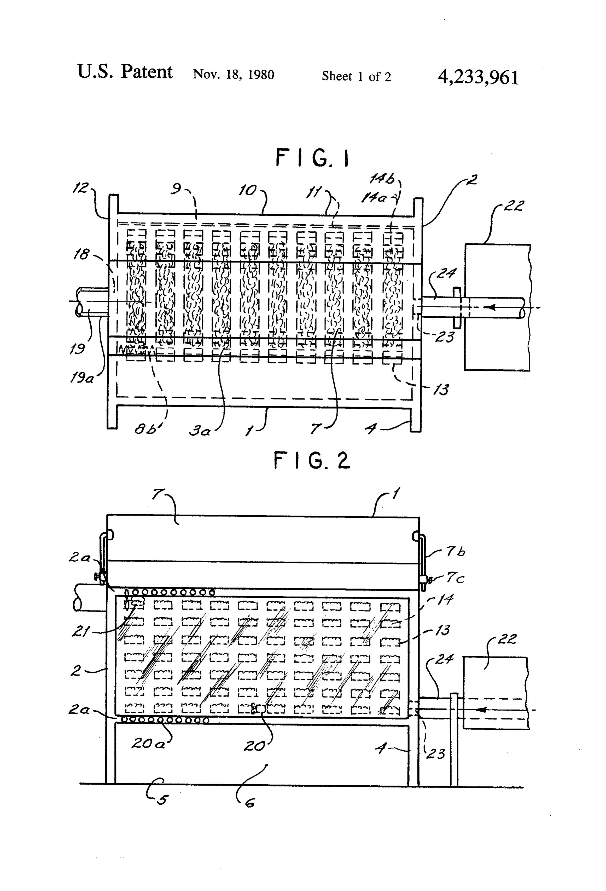
er-than-normal total wattages due to the combined di No. 077,339-Solar Conversion Siding. rect and reflected solar insolation. The solar photovol REFERRING TO THE DRAWINGS taic cells used must be of a type that can withstand the prolonged effects of double solar exposure-(2X/-2 FIG. 1 is a plan view of the suspended, hot-box solar suns) without measurable long-term deterioration. 50 collector.
Another possible option for utilizing the normally FIG. 2 is a front elevation view of the suspended, excessive summer time solar heat within the hot box is hot-box solar collector.
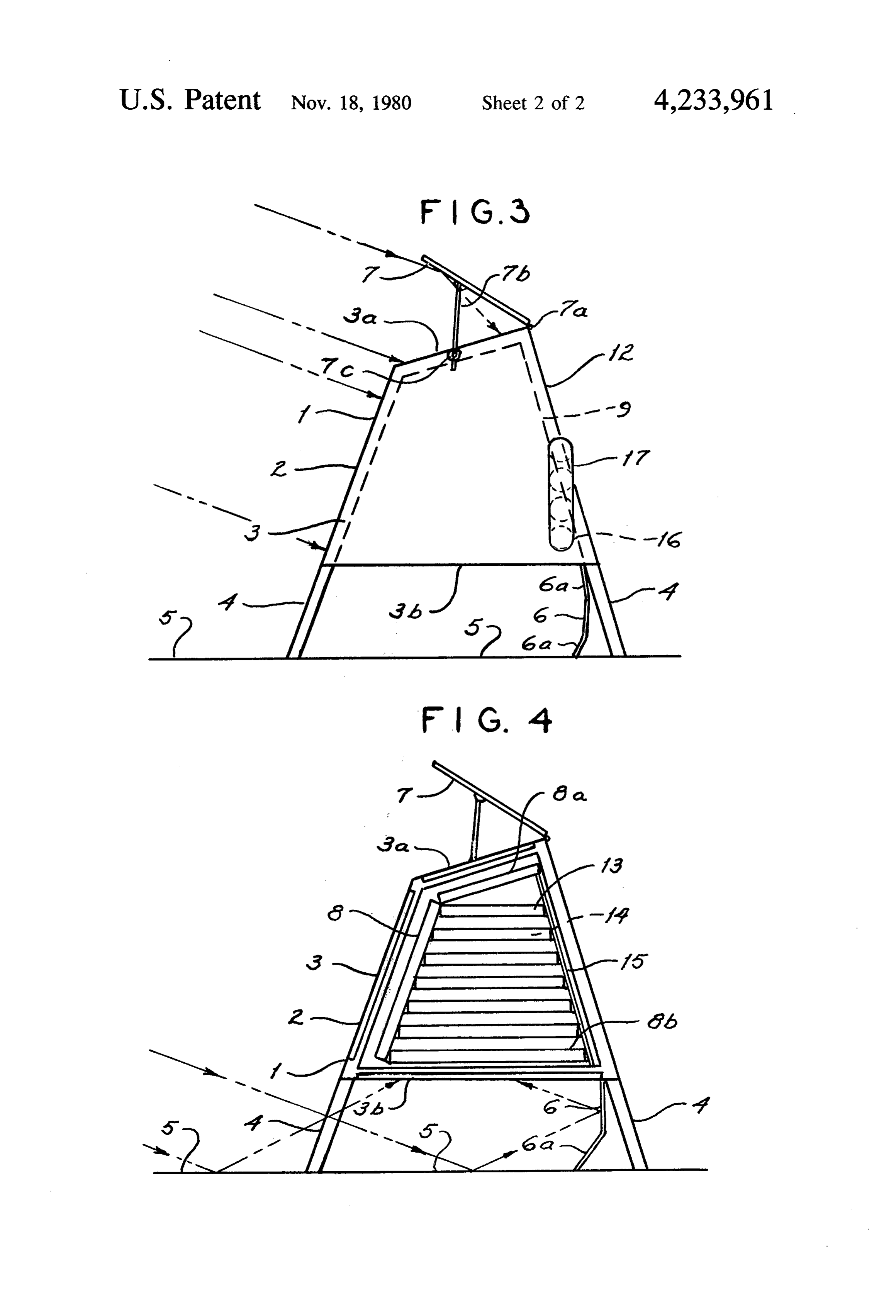
that of preheating water prior to its transfer into a hot FIG. 3 is a side elevation of the suspended, hot-box water-to-steam solar concentrator arrangement which solar collector.
is placed in-line or adjacent to the suspended, hot box 55 FIG. 4 is a cross-section through the suspended, hot unit(s). It is possible that both summer time modes of box solar collector.
operation may be utilized with the top double-glazed DESCRIPTION OF THE PREFERRED window section providing the water preheating func EMBODIMENT tion while the converted photovoltaic cell panels cover the front window sections. Removable water heating Referring to the drawings, numeral 1, illustrates the coils may be mounted near the top of the closed cham suspended, hot-box solar collector unit, which is com ber for the water pre-heating function, with tubing prised of an insulated hot-box chamber 2, containing connections provided at the outside faces of the unit. front, top and bottom double-glazed window sections 3, A second, optional 110 V.A.C. air moving fan/motor 3a and 3b, respectively.
may be required within the closed chamber to circulate 65 The hot-box chamber 2, is raised approximately one the collecting hot air towards the duct outlet and the third of its height by four corner posts 4, which are primary air moving fan with the duct outlet section. securely fastened to the ground or flat rooftop surface. Both fans will be energized together and preferably The front, double-glazed window section 3, must ex 7 actly face south, at a mean winter/summer solar slope Several alternative components for the hot box solar angle for the latitude of the unit installation. collector unit 1, must also be described, since they be The hot-box chamber 2, must be level in the front and come practical for use when the first described compo side directions, with adequate clearance from all sur nents are not available, or not as effective for some rounding buildings, trees and other obstacles, so that no, installations, or a minimum of daily solar overshadowing occurs on An alternate for the blackened, corrugated aluminum the unit, absorber plate 8, will be the "V" form of absorber plate A front reflective panel 5, comprised of aluminum/- 8 which consists of multiple, identical strips of black mylar film or conventional plastic mirrors extend out 10 ened aluminum sheet of about 4 inches to 5 inches in from under the hot-box chamber 2, in a southerly direc width which are riveted or crimped together along tion from the unit 1, a distance equal in length to the their lengths. This type of absorber configuration will height of the hot box solar collector unit 1. A lower, provide a very large total surface area for heat absorp rear reflective panel 6, which is made up of two or three tion within a limited window surface area. An alternate for the eutectic salts heat absorbing longitudinal planes 6a, is located at an angle between material the front reflective panel 5, and the rear area of the 15 with 14, will be thin aluminum foil which is coated bottom double-glazed window section 3b, a uniform layer of a eutectic salt solution with A top reflective panel 7, is located at an angle at the aluminum paint used as the vehicle for the solution. rear, top edge of the top, double-glazed window section After the salt/paint solution is dry, the aluminum foil 3a, and secured by a piano hinge 7a, with support rods 20 will be uniformly crumpled into compact volumes for placement into the existing elongate trays 13.
7b, and lock screws 7c, holding the reflective panel 7, at This method of heat storage is a way to disperse the the required seasonal reflective angle. density of the eutectic salts alone, and introduce a sec A blackened, corrugated aluminum absorber plate 8, ond heat storage medium, namely the metal foil with its is located closely behind the front double-glazed win dow 3, along with similar absorber plates 8a, and 8b, 25 myriad of internal passages and cavities, lined with the located closely inside of the top and bottom double indicatedsalt eutectic layers. The aluminum foil volumes will be as 14a, and the eutectic salt layers as 14b.
glazed window section 3a and 3b, respectively. For special applications where the suspended, hot The hot-box chamber 2, and the four corner posts 4, box solar collector unit 1, is used for additional heat are made of standard available materials and conven tional insulation 9, is fully applied between the sheath 30 storage from linear parabolic concentrators 22, an en trance hot air port 23, will be required within the hot ing layers 10, of the unit sides and rear faces. Foil insula box chamber 2. A flexible, insulated transfer duct 24, tion 11, is applied on the inside and outside of the will connect one end of the concentrators 22, air duct sheathing layers 10, with aluminum siding 12 secured to with the entrance hot air port 23.
the outside of the hot-box chamber 2. What is claimed is:
Multiple, identical elongate trays 13, containing eu 35 1. A suspended hot box solar collector comprised of tectic salts 14, or other type of heat storage material, are a closed insulated chamber containing front, top and uniformly and horizontally arrayed within the interior bottom double-glazed transparent windows, of the hot-box chamber 2. The elongate trays 13, and said closed insulated chamber consists of an angular salts 14, are attached to the rear surface of the front truncated triangular cross section shape which is absorber plate 8, and to a generally vertical aluminum constructed in any convenient modular length, grid frame 15. said closed insulated chamber is elevated approxi An inlet air port 16, is located at the lower side or mately one-third of its total height by four corner rear area of the hot-box chamber 2, which contains a posts which are integral with the said closed insu medium mesh screen 16a. A duct extension 17, is con lated chamber, nected to the inlet air port 16, which is formed in sev 45 a fixed horizontal reflective surface disposed directly eral loops of blackened aluminum sheet, to provide a under said closed insulated chamber at base level in pre-heating function for the intake air into the unit 1. a southerly direction in front of said suspended hot An outlet air port 18, is located at the upper side or box solar collector to a distance nearly equal to rear area of the hot-box chamber 2, opposite from the one-third the total height of said closed insulated inlet air port 16. Hot air transmission ducting 19, is SO chamber, connected to the outlet air port 18, to transmit the hot a three plane reflective element disposed at the rear air to the home or building, with insulation 19a, cover bottom of said closed insulated chamber with the ing the ducting 19, to minimize heat losses. lower front edge secured to said fixed horizontal Multiple, small D.C. fan/motors 20 are uniformly reflective surface, located within the hot-box chamber 2, to slowly move 55 the opposite top edge of said three plane reflective the collecting hot air over the elongate trays 13, and element angled upward toward the rear lower face salts 14, and subsequently toward the outlet air port 18. of said bottom double glazed transparent window, The multiple, small D.C. fan/motors are powered by an an adjustable top reflective surface disposed at an array of silicon photovoltaic cells 20a, located along the adjustable angle at the rear top northern edge of front edges and front divider strips 2a, of the hot-box said top double-glazed transparent window, chamber 2. By utilizing silicon photovoltaic cells in this a continuous piano type hinge secured at the rear top way the hot air movement within the hot box chamber northern edge of said top double-glazed transpar 2, is automatic and proportional to the degree of solar ent window and the underside of said adjustable insolation on the hot box solar collector unit 1. top reflective surface,
A 110 V.A.C. 21 fan/motor is located in-line with the 65 twin support rods secured at the sides of said adjust outlet air port 18, on the inside of the hot box chamber able top reflective surface and fastened to the 2, to provide positive displacement of the heated air into upper sides of said closed insulated chamber by the hot air transmission ducting 19. means of twin locking screws, adjustment means 8 for said twin support rods within said twin locking said front bouble glazed transparent window is dis screws, posed at the correct average seasonal sun slope a black corrugated metal absorber plate disposed angle corresponding to the latitude of each specific behind the rear face of said front double-glazed installation site.
transparent window, a horizontal black corrugated 5 5. A suspended hot box solar collector according to metal absorber plate disposed under said top dou- claim 1, in which said closed insulated chamber is ele ble-glazed transparent window, a horizontal black vated not exceeding one-half of the height of said closed corrugated metal absorber plate disposed above the insulated chamber, inner face of said bottom double-glazed transparent said closed insulated chamber elevation shall not be window, 10 less than one-quarter the height of said closed insu multiple identical perforated metal trays uniformly lated chamber, and horizontally disposed within the interior of said four corner posts are extensions of the end fram said closed insulated chamber, attachment of the ing members of said closed insulated chamber, front ends of said multiple identical perforated the angle of said angular truncated triangular cross metal trays to the rear nearly vertical surface of 5 section shape may be varied to correspond to opti said black corrugated metal absorber plate, attach mum solar ray fall during the winter season for the ment of the rear ends of said multiple identical latitude of the installation site. perforated metal trays to a rear metal grid frame 6. A suspended hot box solar collector comprised of work within said closed insulated chamber, a closed insulated chamber containing a major front eutectic salts uniformly dispersed within each of said 20 double glazed transparent window, multiple identical perforated metal trays, said closed insulated chamber contains a minor top an inlet air port disposed at the lower rear corner of double-glazed transparent window, said closed insulated chamber, said closed insulated chamber contains a major bot an outlet hot airport disposed at the upper side of said tom double-glazed transparent window, closed insulated chamber opposite from said inlet 25 said closed insulated chamber consists of a truncated air port, triangular cross section shape which is constructed a motor driven fan disposed in line with said outlet in any convenient modular length, hot air port on the inside of said closed insulated said closed insulated chamber is elevated approxi chamber, mately one-half of its total height by four corner multiple small D.C. motor driven fans uniformly 30 posts which form the end framing members of said disposed within said closed insulated chamber, closed insulated chamber, multiple silicon photovoltaic solar cells mounted a fixed generally horizontal reflective element dis along the outside front strip surfaces of said closed posed directly under said closed insulated chamber insulated chamber, to power said multiple small at base level in a true southerly direction in front of D.C. motor driven fans. 35 said suspended hot box solar collector to a distance 2. A suspended hot box solar collector according to not exceeding one-half the total height of said claim 1, in which said inlet air port is externally con closed insulated chamber, nected to a black metal duct extension formed in one or a three plane reflective element disposed at a forward more continuous loops, sloping angle to said fixed generally horizontal said inlet air port contains a medium mesh screen 40 reflective element with the lower front edge in over the full port area, contact with said fixed generally horizontal reflec said outlet hot air port is externally connected to a tive element, continuous duct which is routed underground to the opposite upper rear edge of said three plane re the home or building, flective element in contact with the rear edge of full insulation means over said continuous duct above 45 said major bottom double-glazed transparent win ground from said closed insulated chamber and dow, below ground to the said home or building. an adjustable upper reflective element with its reflec 3. A suspended hot box solar collector according to tive surface disposed downward into said minor claim 1, in which said closed insulated chamber is con top double glazed transparent window, said adjust structed of double layers of plywood sheathing with 50 able upper reflective element is hinged at the rear fiberglass insulation placed between the layers of ply top northern edge of said closed insulated chamber, wood sheathing, twin support rods and twin adjustable locking aluminum foil secured to the inside faces of said dou screws disposed at the sides of said closed insulated ble layers of plywood sheathing, chamber with the said twin support rods pivoting vapor barrier material fastened to the outside layer of 55 within the sides of said adjustable upper reflective plywood sheathing, element, aluminum siding fastened to the outside of said vapor a black metal absorber plate in Vee form disposed barrier material as the final surface of said closed behind the rear face of said major front double insulated chamber. glazed transparent window, 4. A suspended hot box solar collector according to 60 said blacke metal absorber plate in Vee form made up claim 1, wherein said three plane reflective element is of multiple identical vertically elongated strips adjusted and fixed to provide maximum reflected solar uniformly fastened together along their lengths, ray distribution into said bottom double glazed trans a black metal absorber plate in Vee form horizontally parent window during the winter season, disposed under said minor top double glazed trans said adjustable top reflective surface is seasonally 65 parent window, adjusted and fixed to provide maximum reflected a black metal absorber plate in Vee form horizontally solar ray distribution into said top double glazed disposed above the inner face of said major bottom transparent window, double glazed transparent window, 9 multiple identical perforated metal trays uniformly suitable siding fastened to the outside of said vapor and horizontally disposed within the full interior of barrier material as the final outer surface of said said closed insulated chamber, closed insulated chamber.
attachment of the front ends of said multiple identical 8. A suspended hot box solar collector according to perforated metal trays to the rear nearly vertical 5 claim upper 6, wherein said outlet hot air port disposed at the side of said closed insulated chamber is externally surface of said black metal absorber plate in Vee connected to a continuous large duct which is routed form, attachment of the rear ends of said multiple underground to the home or building, identical perforated metal trays to a rear vertical full insulation means over said continuous large duct metal grid framework within said closed insulated 10 above ground from said closed insulated chamber chamber, and below ground to to the said home or building, uniformly crumpled aluminum foil evenly placed said flexible insulated transfer air duct disposed over within all of said multiple identical perforated said inlet air port is kept as short as practical for metal trays, bonding of a thin layer of eutectic salts connection to said focal hot air linear duct of a to said uniformly crumpled aluminum foil with a 15 series of linear parabolic concentrators, suitable paint vehicle, moderate dense forming of said inlet airport contains a fine mesh screen over the said uniformly crumpled aluminum foil to produce full port area, a myriad of passages and cavities lined with eutec suitable support and securing means for said flexible tic salt solution within said uniformly crumpled insulated transfer air duct. aluminum foil, 9. A suspended hot box solar collector according to claim an inlet air port disposed at the lower side corner of form has 6, in which said black metal absorber plate in Vee a plain non-blackened rear non-solar facing said closed insulated chamber, a flexible insulated surface, transfer air duct disposed over said inlet air port a coating of a thin layer of eutectic salt solution on the connected to the focal hot airlinear duct of a series 25 plain non-blackened rear non-solar facing surface, of linear parabolic concentrators adjacent to said a coating of a layer of eutectic salt solution on all suspended hot box solar collector, interior surfaces of said closed insulated chamber, an outlet hot airport disposed at the upper side of said said black metal absorber plate in Vee form fabricated closed insulated chamber opposite from said inlet in one continuous plate with uniform Vee bends air port, 30 vertically disposed on said black metal absorber a motor driven fan disposed in line with said outlet plate in Vee form, hot air port on the inside of said closed insulated the proportions of said Vee form black metal ab chamber, sorber plate are not less than three units in depth to multiple small D.C. motor driven fans uniformly 35 one unit of width to provide a uniformly sharp Vee configuration for the said black metal absorber disposed within said closed insulated chamber, plate.
multiple silicon photovoltaic cells mounted along 10. A suspended hot box solar collector according to the outside front strip surfaces of said closed insu claim 6, wherein said closed insulated chamber is ele lated chamber, to power said multiple small D.C vated not to exceed one-half the height of said closed motor driven fans. 40 insulated chamber, 7. A suspended hot box solar collector according to said closed insulated chamber elevation shall not be claim 6, in which said suspended hot box solar collector less than one-quarter the height of said closed insu is constructed of an open framework of said angular lated chamber, truncated triangular cross-section shape and modular 45 said four corner posts are extensions which are se length, fastening of plywood surfaces on the inside and cured to said closed insulated chamber as separate outside of said open framework, components of said suspended hot box solar collec tor, suitable full insulation placed between said plywood the angle of said truncated portion of the triangular surfaces with no void spaces left within the struc cross-section shape may be selected for optimum ture, 50 solar ray distribution into said minor top double aluminum foil insulation secured to the inside faces of glazed transparent window, said double plywood surfaces, mounting of said suspended hot box solar collector on vapor barrier material uniformly secured to the out a level ground or rooftop surface. side face of said plywood surfaces,
Provenance
- Collection
- Patents citing this work
- Pages
- 9
- Method
- pdftotext (the PDF's own text layer) + pdftoppm 300dpi page scans
- Patent office record
- patents.google.com →
- Source
- Google Patents citing-documents table
- Assignee
- Kelly Donald A
- Published
- 1980-11-18
- Transcribed from
- patentimages.storage.googleapis.com →