

patent · US4236508A
Solar cooker and method of assembly
2 December 1980
Text
Page 1scan →
United States Patent (19)
Kerr
54). solar cooker and method of
Assembly
(75) Inventor: Barbara P. Kerr, Tempe, Ariz.
(73). Assignee: Elsa D. Cole, Tempe, Ariz.; a part terest
3,301,171 1/1967 Steinberg ............................. 126/451 3,406,811 10/1968 Higley ............ ... 220/331 X
3,741,430 6/1973 Bergh et al. ......................... 220/331 3. 27 E. R a- a - a a - a a a a - a - a - - - - a 126/451
4,082,079 4/1978 Rodgers ............................... 26/451 4,103,805 8/1978 Silverstein ............................ 220/331 4,130,106 12/1978 Clevett et al. ....................... 126/451
Foreign patent documents
2377010 8/1978 France ..................................... 126451 Primary Examiner-James C. Yeung
Assistant Examiner-Larry jones
Attorney, Agent, or Firm-Warren F. B. Lindsley
A method of assembling from kit components a solar oven and in so doing, teaching the assembler the princi pals involving insulation, reflection, solar ray conver sion to heat, temperature conservation and the fine art of cookery.
10 Claims, 8 Drawing Figures
Drawings
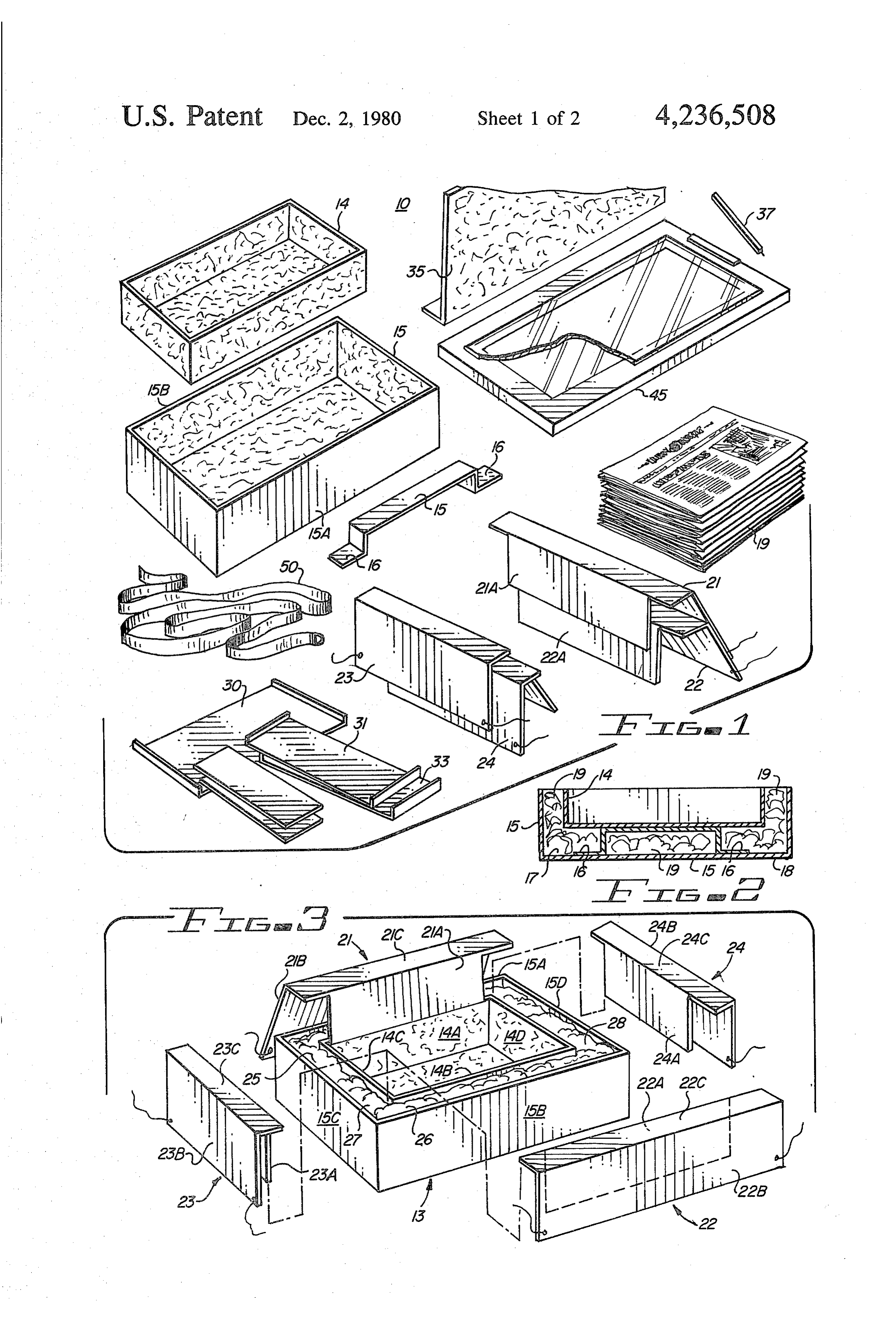
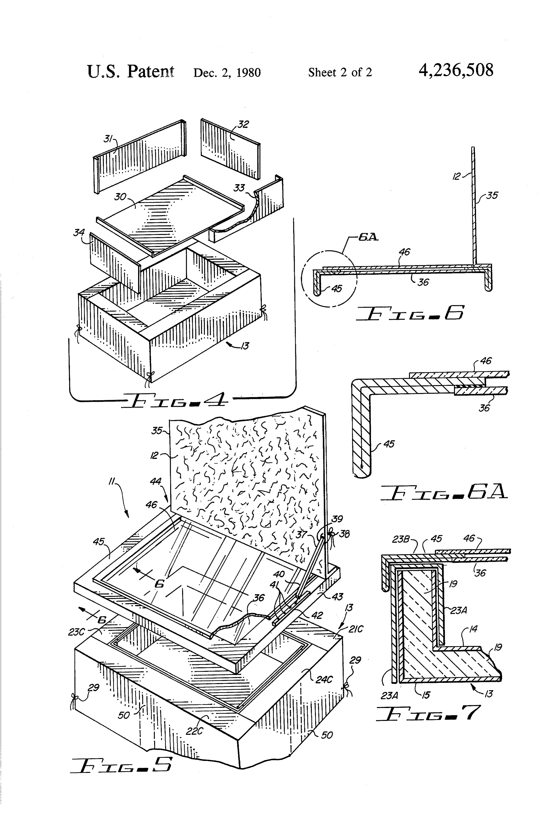
FIG. 3 is a further exploded perspective view of the
Page 2drawing sheetscan →
Page 3drawing sheetscan →
Page 4scan →
claims annexed to and forming a part of this specifica
SOLAR COOKER AND METHOD OF ASSEMBLY tion.
BACKGROUND OF THE INVENTION BRIEF DESCRIPTION OF THE DRAWING This invention concerns apparatus and mechanism 5 byThe present invention may be more readily described reference to the accompanying drawing in which:
for concentrating solar energy, and more particularly FIG. 1 is a perspective exploded view of the compo solar cookers designed to trap the radiant energy of the nents of a kit for assembling a solar oven in accordance sun which is a form of heat and raise the temperature in a specially constructed oven for cooking purposes. This 10 with the teaching of this invention; FIG. 2 is a cross-sectional view of the base of the invention is further directed to a kit for assembling such a cooker from readily available components, teaching assembled oven showing the heating surface supported the assembler in so doing the value and characteristics above and insulated from the bottom and sides of the of its various components. oven;
FIG. 3 is a further exploded perspective view of the
PRIOR ART 15 components of the kit at a point in the solar oven's Solar cookers of various Spes have been known but construction;
FIG. 4 is a still further exploded perspective view of their principals of construction and operation have not been generally understood by the users and particularly the construction of the solar oven illustrating the com youngsters learning the values of insulation, conserva ponents and assembling of the lining of the cooking tion, solar ray phenomenon and the fine art of cookery. 20 compartment;
U.S. Pat. No. 3,236,227 discloses an auxiliary heating FIG. 5 is a still further exploded perspective view means for solar ovens, but it does not disclose a simple illustrating the cover and solar ray reflective surface of kit from which a solar oven can be constructed, at the the oven;
same time teaching by its assembly the characteristics 25 FIG. 6 is a cross-sectional view of FIG. 5 taken along and value of its various components. the line 6-6;
U.S. Pat. No. 3,938,497 discloses an apparatus for FIG. 6A is an enlargement of the circled area 6A of solar cooking employing a frame or base readily mov FIG. 6; and able for locating the apparatus in a favorable exposure FIG. 7 is a partial cross-sectional view of the solar to the sun. The oven disclosed is tiltable on the frame to follow the sun. 30 oven shown in FIGS. 1-6 illustrating the cover in cook ing position.
U.S. Pat. No. 4,018,212 discloses a solar heating and cooking apparatus disclosing a housing permanently DESCRIPTION OF THE PREFERRED stationed inside a residential structure employing a radi EMBODIMENT ation pipe extending through the exterior wall of the 35 Referring more particularly to the drawings by char building to deliver a concentrated beam of solar radia acters of reference, FIG. 1 discloses the component tion rays to a receiver. parts for a kit 10 assembling a simple but effective solar None of the patents disclose a simple structure that oven 11 shown in FIG. 5 while making obvious in its can be built by the young from a kit so that they can not assembly the characteristics and benefits of its compo only assemble an operable solar oven, but also learn nent parts.
about its characteristics and direct use of solar energy The solar cooker comprises a well insulated box with while assembling the oven. one reflecting surface 12 which aids in concentrating SUMMARY OF THE INVENTION the solar rays in the oven portion 13 of the solar oven. In accordance with the invention claimed, a novel topAsboxes shown in FIG. 1, the kit 10 comprises two open 14 and 15 which may be formed of cardboard method and kit are provided for building a solar oven with box 14 while teaching the characteristics of the oven and its within box 15being of such a size that it can be placed in spaced arrangement thereto in the component parts during assembly as well as teaching some of the characteristics of the fine art of cookery manner shown in FIGS. 2 and 3. In order to space and hold the small box 14 in the position shown in FIG. 2, a during its use.
It is, therefore, one object of this invention to provide 50 brace 15 may be utilized and placed with its flanges or legs 16 positioned to rest on the inside surface 17 of the a method and kit for assembling solar ovens.
Another object of this invention is to provide a kit for bottom 18 of box 15.
Suitable insulation 19 which may be crumpled or assembling an efficient solar heating and cooking appa ratus from readily available inexpensive materials wadded newspaper or any other suitable non-toxic form which can be used for cooking purposes and then 55 of insulating material, such as fiberglass, cellulose and quickly dismantled and again re-assembled and used by the like, is placed between the inner and outer posi others thereby repetitively serving as an effective teach tioned boxes 14 and 15 to fill the cavity therebetween. It ing aid. should be noted that this space may also be simply an air A further object of this invention is to provide an space which also is one form of an insulating medium. improved effective kit assembled solar cooker which is 60 itsThe next step in the assembly of the solar oven from component parts is to position topper spacers 21, 22 convenient to use in cooking operations.
A still further object of this invention is to provide a and 23, 24 in position for straddling the space between solar ray concentrator of relatively low cost and size the juxtapositioned boxes 14 and 15, thereby interlock producing an economical source of power. ing them together but at the same time closing the Further objects and advantages of the invention will 65 spaces between the boxes 14 and 15 so that these spaces become apparent as the following description proceeds form an effective insulating medium.
and the features of novelty which characterize this As noted from FIG. 3, the topper spacers 21 and 22 invention will be pointed out with particularity in the formed in a U-shaped configuration are positioned with 5 their narrower legs 21A and 22A arranged to lie along of the components of the cooker in a compact arrange and juxtapositioned to the inside surfaces i4A and 14B ment.
of box 14 and with their legs 21.B and 22B lying juxtapo With proper utensils containing the food to be sitioned to and along the outside surfaces 15A and 15B cooked placed in the solar cooker 10 on top of a grid or of box 15. The bight or interconnecting portions 21C tray positioned within box 14 and with a suitable ther and 22C of the spacers close the sides of the spaces 25 mometer placed adjacent thereto, the cooker is turned and 26 between the boxes 14 and 5. toward the sun with cover 35 propped up so that its Topper spacers 23 and 24 are formed in a U-shaped reflective surface squarely faces the sun. The cover 35 is configuration similar to spacers 2 and 22 and are ar then hingedly moved until its reflective solar rays are ranged to have their legs 23A and 24A and 23B and 24B 10 directed into the hollow interior of box 14 and onto the lie adjacent the inside surfaces 4C and 14D of box 14 utensils. At this point, the cap lid 45 is resting on the top and the outside surfaces 15C and 15D, respectively, in surfaces of the topper spacers 21-24 so as to capture all the manner of spacers 21 and 22 with their bights 23C of the heat directed in box 14 either directly by the sun and 24C covering the insulating spaces 27 and 28. Tie or reflected thereinto by the reflective surface of cover strings 29 with one string attached to each of the cor 15 35. The brace 37 is used in the normal manner to keep ners of each of the spacers as shown in FIG. 5 are used the cover 35 in its selected position. to hold the topper spacers to the outside surface of box Although the disclosed solar cooker may be formed 5. essentially from cardboard components, the cooker can In order to make the inner surfaces of box 14 more be made of any other suitable material, such as wood, heat absorbing, these surfaces may either be covered or 20 fiberglass or plastic and still fall within the scope of the painted with a black heat absorbing paint or material. disclosed invention.
As shown in FIG. 4, the bottom and inner sides of box It will now be recognized that a significantly im 14 may be covered with suitable black foil liners 30, 31, proved solar oven or cooker is provided over the prior 32, 33 and 34 or more firmly constructed black surface art in accordance with the stated objects of the inven liners, if so desired. These liners may interlock together 25 tion, and while but one embodiment of the invention has in any suitable manner so that they may be readily disas been illustrated and described, it will be apparent to sembled when necessary. those skilled in the art that various changes and modifi The inside of cover 35 of the cooke, may comprise cations may be made therein without departing from reflector 2. his cover may be hingedy attached at the the spirit of the invention or from the scope of the ap edge of the glazing opening on the top of cap lid 45 in 30 pended claims.
any suitable manner. One satisfactory method is to use a What is claimed is:
cloth material glued to the outside surface of cap lid 45 1. A solar oven comprising: and the juxtapositioned edge of the outside, non-reflec a first box having an open top, tive surface of cover 35. a second box having an open top of a smaller size than The cap lid 45 which may rest on the bights of topper 35 said first box and arranged within and spacedly spacers 21, 22, 23 and 24 and over lap the top peripheral positioned from the bottom, sides and ends of said edge of box 15 incorporates a transparent member such first box, as glass 36, as illustrated in FIGS. 5 and 7. the inside surface of said second box having a heat As shown in the drawing for purposes of illustration, absorbing surface, a plate of plastic material 46 is spacedly positioned from topper spacer means closing the space between said glass 36 with this material simply laid onto or suitably first and second boxes at their open tops, fastened to the top surface of cap lid 45. Glass 36 may be said topper spacer means comprising two pairs of fastened such as by a silicone seal to the under surface of U-shaped clamps for positioning over the edges of the cap lid 45 as shown in FIGS. 6 and 6A. The reason the periphery of the tops of said first and second for using the plastic material 46 in lieu of glass is to 45 boxes to cover the space therebetween and hold protect children from breakage when making and using the boxes in a given position relative to the other, the solar cooker. each clamp of each pair comprising a pair of legs In order to hingedly position cover 35 in one of a interconnected by a bight, number of annular positions relative to the top of cap lid the legs of said first pair of clamps fitting over the 45, a brace 37 is utilized which may be loosely attached 50 opposed surfaces of different juxtapositioned ends at one end by a string bow 38 passing through an aper of the first and second boxes, ture in end 39 of brace 37 and a couple of spaced holes the legs of the second pair of spacers fitting over the in cover 35 and tied together, as shown in FIG. 5, or opposed surfaces of a different juxtapositioned side secured in one of a number of appropriate flexible ways. of the first and second boxes, The other end 40 of brace 37 may have a tapered config 55 the bights of the clamps covering the spaces between uration for fitting into one of a number of spaced said first and second boxes at their open tops, grooves 4 in a rail 42 fastened along the top surface of a transparent enclosing means comprising a cap lid cap lid 45. resting above the edges of the open tops of said first It should be noted that a method for forming a novel and second boxes and on the topper spacers for solar cooker has been disclosed, the assembly of which 60 closing the open top end of said second box, aids in teaching the principles of energy use and conser said enclosing means comprising a pair of spaced vation as related to solar energy and further as a method transparent plates having a closed air space there for forming a useful apparatus for cooking various foods between, and placed in cooking utensils placed on a grid or directly a reflective means of substantially the same size as the on the top surface of the bottom of box. 14. 65 opening of said first box hingedly attached to said When the cooker is not in use, a strap 50 may be cap lid for selective movement relative thereto, and placed around the cooker with its cover 35 pivoted in detachable brace means arranged to extend between parallel arrangement with the cap lid 45 to maintain all said reflective means and said top of said cap lid for 6 holding said reflective means in one of a plurality placing an open top box within a second open top box of angular positions relative to the top of said cap in spaced arrangement therewith with the periph lid for directing solar rays into the opening of said eries of the opening of said boxes being coplanar, second box. covering the inside surface of said second box with a 2. The solar oven set forth in claim 1 in further combi heat absorbing material, nation with: filling the space between said boxes with an insulating insulating means positioned within the space between material, said first and second boxes. placing clamp means over the peripheral edges of 3. The solar oven set forth in claim 1 wherein: said first and second boxes for closing the space said enclosing means comprises a pair of spaced trans 10 between the boxes and for holding them in a fixed parent plates, position one relative to the other, the exposed one, when in oven closing position, clos placing a transparent cap lid, enclosing member com ing the openings of said first and second boxes, prising a pair of spaced plates enclosing an air comprises a plastic material. space therebetween across the open end of the 4. The solar oven' set forth in claim 3 wherein:
said enclosing means comprises a cardboard cap lid hingedly mounting a reflective surface of a similar having said plastic material positioned on the top of size to the opening of said second box on the top periphery of the cap lid for reflecting solar rays the cap lid, and into said first box, and a glass lid.
plate adhered to the bottom surface of the cap selectively moving said reflective surface to orient it to the sun.
5. The solar oven set forth in claim 1 wherein: 9. The method set forth in claim 8 wherein: the open peripheries of said first and second boxes are said enclosing member comprises a pair of spaced coplanar. plates, the exposed one of which is formed of a 6. The solar oven set forth in claim 1 in further combi 25 transparent plastic and the other one comprising a nation with: plate of transparent glass, means for fastening together the legs of the clamps said enclosing member extending down over the around the outer periphery of the box. edges of said clamp means covering the boxes in a 7. The solar oven set forth in claim 1 wherein: capping fashion.
said first and second boxes and said clamps are 30 10. The method set forth in claim 8 wherein: formed of cardboard or other suitable material. said boxes and clamps are formed of cardboard or 8. A method for assembling a solar oven comprisin other suitable material.
the steps of:
Provenance
- Collection
- Patents citing this work
- Pages
- 6
- Method
- pdftotext (the PDF's own text layer) + pdftoppm 300dpi page scans
- Patent office record
- patents.google.com →
- Source
- Google Patents citing-documents table
- Assignee
- Elsa D. Cole
- Published
- 1980-12-02
- Transcribed from
- patentimages.storage.googleapis.com →