

patent · US4238246A
Solar energy system with composite concentrating lenses
9 December 1980
Text
Page 1bibliographic recordscan →
United States Patent (19)
Genequand et al.
54 SOLAR ENERGY SYSTEM WITH
COMPOSITE CONCENTRATING LENSES
75 Inventors: Pierre Genequand, Geneva,
Switzerland; Virgil Stark, New
York, N.Y.
73 Assignee: North American Utility Construction
Corp., New York, N.Y.
(51) Int. Cl............................. H01L 3/04; F24J 3/02 52 U.S. C. .................................. 136/248; 126/438:
affittit SS
3,985, 118 10/1976 Bard ..................................... 126/425 4,022,186 5/1977 Northrup, Jr. ... ... 126/440 4,069,812 1/1978 O'Neill ............. ... 36/89 PC 4,134,393 1/1979 Stark et al. ................. 136/89 HY X Primary Examiner-Aaron Weisstuch
Attorney, Agent, or Firm-Kenyon & Kenyon
In order to improve the efficiency of a solar energy system utilizing a Fresnel lens for concentrating solar rays on a conduit system or the like, only the central portion of a Fresnel lens, otherwise of large width, is utilized and slide assemblies, each containing a plurality of slats with a reflective coating and disposed at an angle such as to reflect solar energy to the same focal point as the Fresnel lens, are disposed on each side of the lens thereby effectively increasing the aperture of the lens and increasing efficiency of concentration. 10 Claims, 1 Drawing Figure
Drawings
Page 2drawing sheetscan →
Page 3scan →
Summary of the invention
Solar energy system with composite
CONCENTRATING LENSES It is thus the object of the present invention to pro vide an improved concentrating lens assembly for use in
BACKGROUND OF THE INVENTION 5 a solar energy system.
The present invention accomplishes this object by
This invention relates to solar energy systems in gen utilizing only the central part of a linear Fresnel lens eral and more particularly to an improved concentrat where the highest efficiency of transmission is obtained. ing lens arrangement for use in solar energy systems. For example, only 60 cm in the central section of what Various solar energy systems have been developed. O would otherwise be an 86 cm wide lens is used, thereby Of particular interest are the types of systems disclosed insuring a minimum efficiency of about 85%. In order in U.S. Pat. No. 4,134,393 and in Ser. Nos. 866,067 filed to still provide a wide aperture to obtain greater con Dec. 30, 1977, 866,068 filed Dec. 30, 1977, 806,291 filed centration of solar energy, adjacent to the Fresnel June 15, 1977,845,862 filed Oct. 31, 1977, 807,513 filed lenses, on each side, a set of reflective slats, termed a June 20, 1977,915,001 filed June 13, 1978,920,288 filed 5 slide assembly, installed in a frame and supported so as June 29, 1978, and 1,175 filed Jan. 5, 1979 all of which to reflect incident solar rays onto the same focus as the are assigned to the same assignee of the present inven focus of the Fresnel lens are provided. In order that all slats reflect energy on the same focal point, they are at tion.
A number of these systems utilize Fresnel lenses varying angles depending on the distance from the cen made of waterwhite glass in the largest sizes available 20 ter of the lens and are spaced from each other in such a manner so as to not shadow an adjacent slide which is throughout the world. For example, they are up to 86 inclined cm in width by 240 cm in length. Fresnel lenses are differentatwidths a slightly different angle. The slats can have up to about 4 cm. The slats can have an particularly attractive for concentrating solar energy aperture of, for example, from 50 to 90 cm and will have because of their low price. This permits systems of the 25 the same length as the Fresnel lens, i.e., in the example, nature described in the aforementioned patent and ap about 240 cm. If one assumes focusing the energy on a plications to produce energy more economically than 4 inch conduit system and also assumes a 60 cm wide other previously existing solar systems. In the afore Fresnel lens with 60 cm wide slide assemblies on each mentioned patent and applications there are various side, the concentration will be from 180 cm down to 4 uses to which the solar energy which is collected may 30 cm or 45 times.
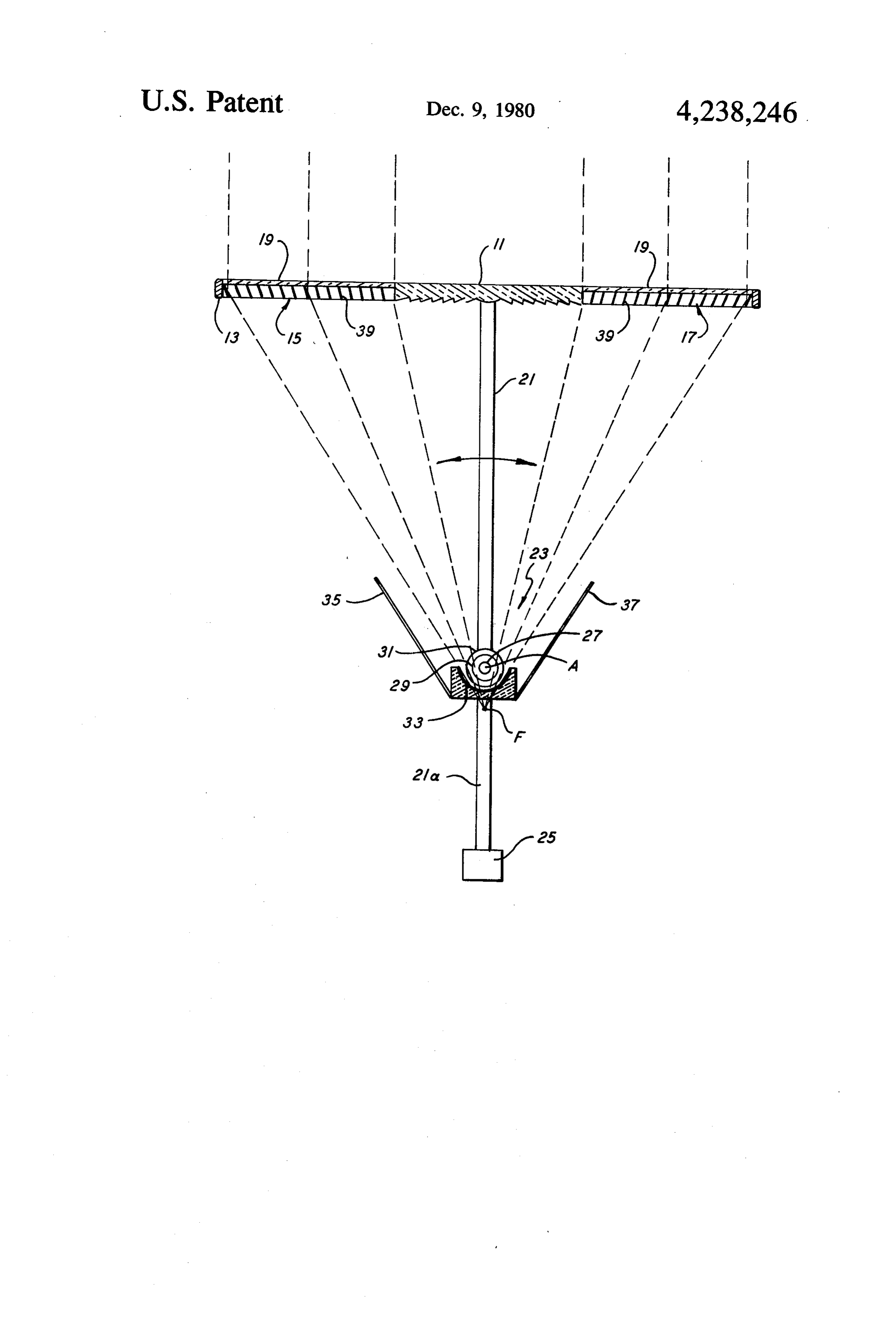
be put. For example, it may be used for heating, refrig BRIEF DESCRIPTION OF THE DRAWINGS eration, distillation of salty water, generation of elec tricity with high efficiency utilizing photovoltaic cells The single FIGURE is an elevation view of a concen and production of electricity or other work through the 35 trating lens arrangement according to the present inven use of thermal energy, i.e., by means of turbines or other tion.
engines. DETAILED DESCRIPTION OF THE In a typical type of system disclosed therein, a Fres INVENTION nel lens is supported above a conduit system which As illustrated by the single FIGURE, a Fresnel lens includes at least an inner and an outer conduit. The 11 of, for example, 60 cm width and 240 cm length, is focus of the Fresnel lens is directed onto or below the disposed in a common frame 13 along with slide assem conduit system so as to concentrate solar energy blies 15 and 17, one on each side of the lens. Each of the thereon. The conduit system normally remains fixed, slide assemblies comprising a plurality on slats 39 is with the Fresnel lens, its frame and an appropriate coun covered by a protective sheet 19 of a transparent mate terweight supported by rotation about the axis of the 45 rial such as glass or plastic. The frame containing the inner tube in the conduit so as to follow the movement Fresnel lens and the slide assemblies 15 and 17 is sup of the sun from east to west during the day. Typically, ported for rotation by means of a central support 21. the whole system is tilted as a function of the elevation Additional supports may also be provided. Rotation is of its location. Tilting may be varied throughout the about the axis A of a concentric tube system indicated year to take into account the varying angle of the sun. 50 generally as 23. The support 21 is extended as a support Although Fresnel lenses have been found the most 21a on the end of which is a counterweight 25 to bal useful and economical, it has been discovered that the ance the weight of the lens arrangement. Appropriate Fresnel lenses conventionally available have a higher motor drives and sensorial systems of the type described in the aforementioned patent and applications will be efficiency of concentration in their central section than 55 provided to rotate the assembly about the axis A to near the edges. This is primarily because the refractive follow the movement of the sun on a daily basis. The prisms in the Fresnel lens cannot be made with sharp ends, thereby causing some dispersion of the solar rays unit will also be tilted with respect to the horizontal depending on its latitude of location and, possibly, the as the number of prisms per unit width is increased toward the edges of the lenses. The efficiency of solar 60 time of year.
Any of the conduit systems described in the afore transmission is, for example, about 90% in the center, mentioned patent and applications can be used as the i.e., from the center of the lens for a distance of about 16 conduit system 23. The illustrated system is a three cm, 85% for about the next 12 cm, 80% for approxi conduit system with an inner conduit 27, and intermedi mately the next 10 cm and then 70-75% toward the ate conduit 29 and an outer conduit 31. As an example, edges of the aperture. 65 the outside diameter of the conduit system can be 4 cm, It thus becomes evident that there is a need for im in which case, if one assumes a Fresnel lens of 60 cm proving the transmission efficiency of a Fresnel lens width and slide assemblies 15 and 19 of equal width, a used in concentrating solar energy. concentration of 45 times will result. Disposed below 4 the conduit system, assuming that the outer and inter amount of energy collected will depend on the selected mediate conduits at least are of a transparent material, is width as will the concentration of energy. a mirror 33. Also shown are mirrors 35 and 37 on each What is claimed is: - side of the conduit assembly 23 to further aid in concen 1. A concentrating lens arrangement for collecting tration of energy. 5 and focusing solar energy comprising: If desired, solar cells may be disposed within the a linear Fresnel lens having a width limited so that the inner tube as disclosed in the aforementioned applica transmission efficiency thereof does not drop tions. The high concentration which is obtained is par below approximately 85% at its edges; ticularly advantageous for generating electricity using first and second slide assemblies disposed adjacent the solar cells, i.e., photovoltaic cells, since production of two longitudinal edges of said Fresnel lens, each of electricity from the luminous rays (0.4 to 0.75 microns) said slide assemblies comprising a plurality of slats increases almost proportionally with the concentration. having thereon a reflective surface, tilted at an As described in the aforementioned applications, there angle such as to reflect incident solar energy to the will be fluids in the spaces between the tubes. The fluids 15 same focal point as the focus of said Fresnel lens; and between the intermediate or inner and outer tube in particular will absorb infrared radiation to prevent a frame for holding said Fresnel lens and slide assem blies together.
overheating of the solar cells. Furthermore, heat from 2. An arrangement according to claim 1, wherein said the fluid in the inner tube is transferred to the fluids in Fresnel lens has a width of approximately 60 cm and a the outer tube resulting in an efficient heat collection 20 length of approximately 240 cm and said slide assem and transfer, all as explained in detail in the aforemen blies have a corresponding length and a width of up to tioned applications. The filtering of the infrared radia approximately 90 cm.
tion by the fluids, in the case of using photovoltaic cells, 3. An arrangement according to claim 2, wherein said avoids the decrease in electricity production which is slide assemblies have a width of approximately 60 cm. associated with heating of the cell. 25 4. An apparatus according to claim 1, wherein said When used for heating fluids, it will be possible, with slats in said slide assemblies are made of a material se the concentration available with this system, to heat the lected from the group consisting of polished aluminum, fluids circulating in the inside tubes to high tempera aluminized steel, aluminized glass, aluminized plastic, tures of about 300° C. permitting a production of power 30 silvered steel, silvered glass and silvered plastic. by thermal means such as turbines or engines utilizing 5. An arrangement according to claim 1, wherein said the Carnot cycle of absolute temperature. slats in each of said slide assemblies comprise an integral The reflective slide assemblies 15 and 17 which are molded unit with the slats therein coated with a reflec essentially identical each comprise a plurality of slats 39 tive coating.
supported in a frame with a predetermined angle, i.e., an 35 tion6. withThe arrangement according to claim 1, in combina a conduit system for collecting solar energy in angle which will result in incident solar energy being the form of thermal energy and further including: reflected to a focal point located either at or below the (a) support means for supporting said arrangement axis A of the FIGURE. The reflective slats may be over said conduit system so as to be rotatable about made of polished aluminum or aluminized or silvered the axis of said conduit; and steel, glass or plastic. The reflective slats may be indi 40 (b) a counterweight for balancing the weight of said vidually constructed and assembled into the frame in arrangement, whereby said arrangement may be this manner. Alternatively, the whole assembly can be rotated about the axis of said conduit system to molded of plastic or other material and the slats then track the movement of the sun from East to West. properly coated with a reflective material. The slats 7. An arrangement according to claim 6, and further may be of different width and their spacing will be such 45 including a mirrored surface disposed below said con that one does not shadow the other. As noted above, the duit system.
slide assemblies 15 and 17 will be installed in a common 8. An arrangement according to claim 7, and further frame 13 with the Fresnel lens 11. When utilized in the including first and second longitudinally extending mir Northern Hemisphere, the assembly will typically be rors disposed at an angle adjacent opposite sides of said tilted at an angle of, for example, 30 degrees for a 35 50 conduit system to reflect additional radiation thereon. degree latitude. This angle may remain fixed or, if de 9. An arrangement according to claim 6, wherein said sired, it can be varied throughout the year to take into conduit system includes transparent concentric tubes account the elevation of the sun. and further including an array of photovoltaic cells Although only a single unit is illustrated on the FIG disposed within the innermost tube of said conduit and URE, a plurality of units in series and/or parallel can be 55 at least one fluid flowing between the innermost conduit provided much in the manner discussed in the afore and an outer conduit, whereby said fluid will absorb mentioned applications. In such cases, the conduits 23 infrared radiation while passing radiation of a wave length which will activate said photovoltaic cells to of the individual units will be interconnected, either in produce electricity.
series or parallel depending on the needs of the particu 60 10. An arrangement according to claim 1, and further lar system. including a transparent protective sheet disposed over Furthermore, as noted above, the slide assemblies 15 each of said slide assemblies.
and 19 can have widths up to 90 cm. Naturally, the k k sk k
Provenance
- Collection
- Patents citing this work
- Pages
- 4
- Method
- pdftotext (the PDF's own text layer) + pdftoppm 300dpi page scans
- Patent office record
- patents.google.com →
- Source
- Google Patents citing-documents table
- Assignee
- North American Utility Construction Corp.
- Published
- 1980-12-09
- Transcribed from
- patentimages.storage.googleapis.com →