

patent · US4238925A
Gas turbine system with oxygen vapor-fuel system
16 December 1980
Text
Page 1bibliographic recordscan →
United States Patent (19)
Lowther
54 GASTURBINE SYSTEM WITH OXYGEN
WAPOR-FUEL SYSTEM
75 Inventor: Frank E. Lowther, Buffalo, N.Y.
Assignee: Purification Sciences Inc., Geneva,
Related U.S. Application Data
63 Continuation-in-part of Ser. No. 879,969, Feb. 21, 1978,
Int. Cl. ................................................ FO2C3/20
2,715,395 8/1955 Finvoid ........................... 123/119A
3,501,913 3/1970 Brille ................................... 60/39.15 3,696,795 10/1972 Smith et al. ......................... 123/1 A 3,709,203 1/1973 Cettin et al. ..................... 123/119A
Arnbient
Air
3,736,745 6/1973 Karig .................................. 60/39.52 3,775,976 12/1973 Karig .................................. 60/39.33 3,844,113 10/1974 Lookwood .......................... 60/39.52 3,861,367 1/1975 Kelmar ........... ... 123/19 A 3,977,365 8/1976 Vierling et al. .......................... 123/3 4,041,699 8/1977 Schelp ............................. 60/39.51 R
Primary Examiner-Louis J. Casaregola
Oxygen vapor at elevated pressures is utilized as the oxidant component of an oxidant-fuel mixture in a fuel burning system for generating combustion gases which are then mixed with ambient gas and exhaust gases for
driving a turbine wheel of a gas turbine operating in a burn-cool cycle. The oxygen vapor is provided from liquid oxygen which preferably is vaporized by heat exchange with hot exhaust gases from the turbine. The burn-cool system of turbine operation permits the oxy gen vapors to be supplied to the burner of a combustion chamber at high inlet pressures of about 1500 psia, in contrast ot prior art systems which provide low pres
sure oxygen to a chamber for combustion in automobile or turbine engines.
23 Claims, 6 Drawing Figures
(iTOF)
Throttle
57 Products
Drawings
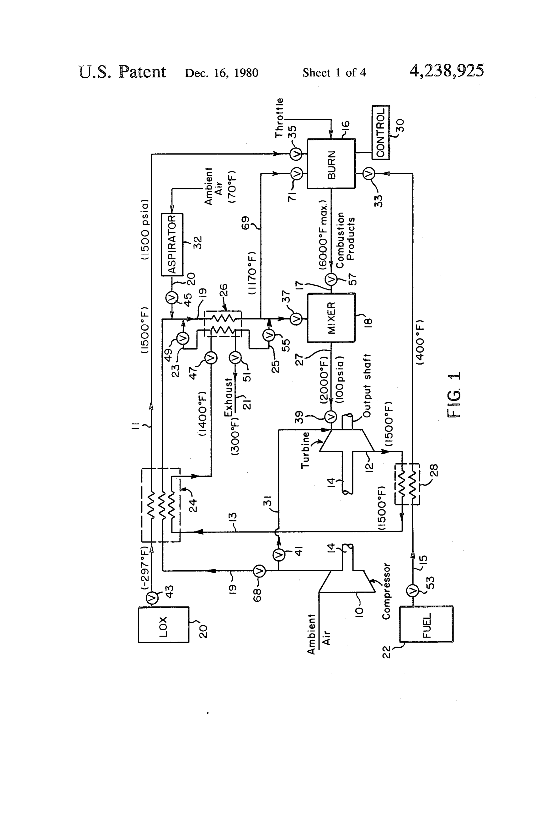
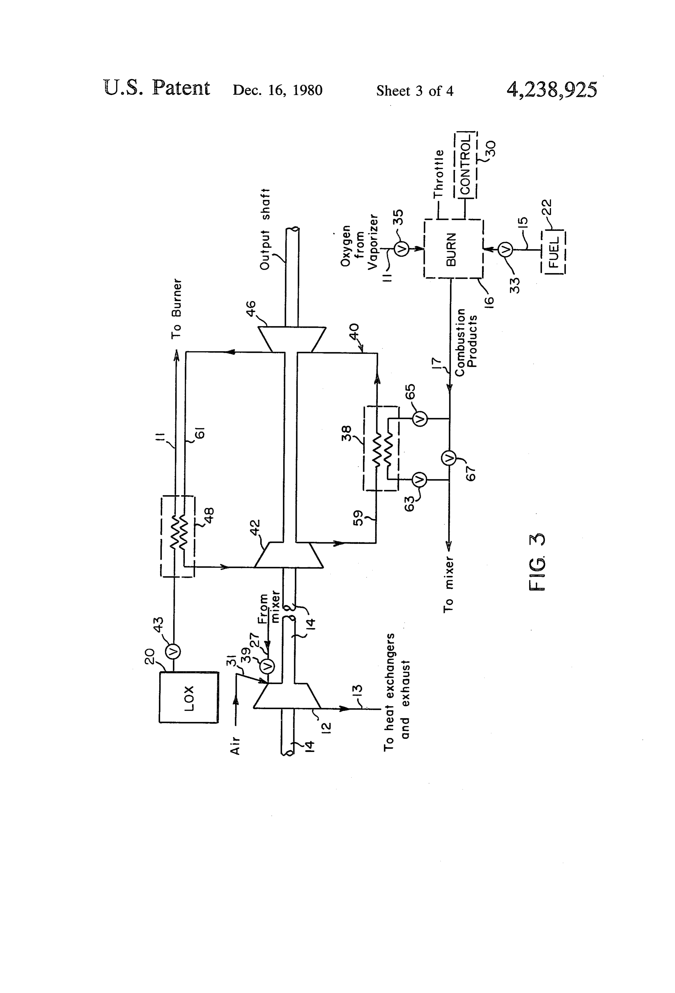
FIG. 1 is a schematic drawing of a Lowther Gas 30 rator 32 can be shut off from line 19 and only the com Turbine thermal power system modified according to pressed air from compressor 10 used in mixer 18. The use of compressed air will be advantageous when the the present invention.
FIG. 2 is a schematic drawing of a modification of the aspirator cannot adequately supply a large enough flow of air for mixing with the combustion products and embodiment of FIG. I.
FIG. 3 is a schematic drawing of another modifica 35 exhaust in mixer 18.
Page 2drawing sheetscan →
Page 3scan →
Turbine
Cold Oxygen Gos
Heat required to roise oxygen to given temperature
5OO Amount of cooling available from pound of liquid oxygen Os a function of the find gas temperature
Page 4drawing sheetscan →
Page 5scan →
Combustion Temperature
Adiabatic for Oxygen/Kerosene Mixture
Oxygen / Fuel Ratio
Dilutant Air Req'd.
Dilutant air req'd. as a and Motor inlet Gas Temp. (T3).
Pressure Ratio 6 of the burn and cool phases to control the power output
GASTURBINE SYSTEM WITH OXYGEN of the turbine. For example, if it is desired to increase WAPOR-FUEL SYSTEM power, the length of the burn phase can be increased, or
Cross-reference to related
the length of the cool phase can be decreased or both.
5 The Lowther Gas Turbine of the related invention
APPLICATIONS also involves the use of different amounts and pressures This application is a continuation-in-part of appli of air during the cool phase than are used during the cant's copending applications: (1) Ser. No. 879,969, filed burn phase. Another aspect of that invention is the use Feb. 21, 1978 and now abandoned, entitled "Gas Tur 10 of water injection during the cool phase to improve bine System'; (2) Ser. No. 889,851, filed Mar. 24, 1978, cooling. The water can be recovered in a condensor and entitled "Gas Turbine System'; and (3) Ser. No. recycled.
890,456, filed Mar. 27, 1978 now U.S. Pat. No. Yet another aspect of the Lowther Gas Turbine in 4,169,017, entitled "Gas Turbine System'. cludes the use of two different fuels, one, for example, can be used in the burn phase and the other in the cool phase. In another embodiment of that invention the
This invention relates to gas turbines and in particular shaft is connected to an electric generator and to a to a Brayton cycle gas turbine. traction motor. A gear box, electric generator and bat BACKGROUND OF THE PRIOR ART tery can also be used in various combinations along In the well-known gas turbines of the compressor 20 with water injection. In addition, a heat exchanger can be used to pre-heat the compressed gas prior to its being combustor type, the turbine blades are remote from the fed into the combustion chamber. combustor and large additional quantities of con The related invention also includes embodiments pressed air are fed to a secondary zone of the combus employing a free turbine. Combined cycle embodiments tion chamber to combine with the hot, expanding com bustion gases, prior to such gases reaching the turbine 25 of the related invention include the use of a second working fluid operating with either an open or closed blades, to reduce the gas temperature to a value that cycle will not cause damage to the turbine blades, see for drive aand with a second working fluid operating to turbine.
example, Gas Turbine Power, Second Edition, 1958, G. Also, the Lowther Gas Turbine includes embodi M. Dusinberre and J. C. Lester; The Gas Turbine En ments using plural turbines and plural burn chambers in gine, 1975, Jan P. Norbye; Automotive Gas Turbines, 30 which the intermittent cycle is employed in each burn Second Edition, 1969, Bill Carroll; and Gas Turbine
Engineering Handbook, First Edition, 1966, John W. chamber. There is a staggered burn cycle from one burn chamber to the next which, in the preferred embodi
Sawyer.
Applicant's related patent application Ser. No. ment, is a uniform staggered burn cycle. A preferred 879,969, filed Feb. 21, 1978, which is incorporated by 35 air-to-fuel ratio is in the range of 14.7:1 to 35:1. A pre reference herein in its entirety, discloses and describes a ferred burn phase to cool phase is 90% to 10% in length Lowther Gas Turbine which comprises a gas turbine of time of the respective phases.
method and apparatus using an intermittent burn oper An example of the intermittent burn-cool cycle of the ating cycle referred to as a burn-cool cycle, comprising Lowther Gas Turbine also is disclosed in applicant's a burn phase followed by a cool phase. This cycle in 40 related copending patent application Ser. No. 889,851, cludes: (1) feeding fuel to the burn chamber and burning filed Mar. 24, 1978, wherein the rate of cooling of the it during the burn phase of the cycle, whereby the tem turbine blades is enhanced by spraying fuel oil directly perature of the chamber and turbine rises during the on the convex surface of the blades thereby shortening burn phase, and (2) cutting off most or all of the flow of the cooling period. Ser. No. 889,851 is incorporated fuel to the burn chamber during the cool phase whereby 45 herein by reference in its entirety. the temperature of the chamber and turbine falls. The FIG. 17 of the above-identified patent application air-to-fuel ratio during the burn phase is always the Ser. No. 879,969, shows an example of a chemical same, providing a high combustion temperature and flywheel. According to the invention disclosed in that high efficiency. The part-load efficiency loss problem of patent application, a cryogenic material, such as dry ice, the prior art is eliminated by the related invention. In 50 liquid air, or liquid oxygen is vaporized and passed the prior art, under part-load, the air-to-fuel ratio was through the gas turbine system during the cooling per increased, thus resulting in a reduced burning tempera iod. The cryogenic material there serves two purposes: ture and reduced efficiency. The combustion tempera it expands and drives the turbine 12, of said FIG. 17, and ture is much higher than the temperature that the struc it cools all the exposed parts that were heated during ture is allowed to reach because of the intermittent burn 55 the burn phase of the burn-cool cycle described in that cycle and the cool down phase, thus eliminating the patent application.
need for high temperature materials. In addition, lower U.S. Pat. No. 3,775,976, issued Dec. 4, 1973, describes amounts of a source of oxygen, such as air, are needed the use of oxygen derived from a cryogenic source as an as compared to the prior art gas turbine. For example, oxidant for a turbine engine in a thermal power system the Lowther Gas Turbine of the related invention uses 60 operated at near atmospheric pressures for a submers about six times smaller volume of gas than does the ible. The patent describes methods and means for opera well-known Chrysler automobile gas turbine. tion of the power system in either a closed or an open The Lowther Gas Turbine also includes means for circuit mode. Some features of the methods and means preventing the shaft speed from decreasing during the for operation of the turbine as described in the patent cool phase. This is accomplished by a flywheel action 65 generally can be utilized in combination with appli using, for example, a mechanical flywheel, an electric cant's Lowther Gas Turbine and with embodiments of flywheel or a chemical flywheel. The related invention applicant's present invention, as will be understood by also includes the controlling of the length of at least one those skilled in the art.
Page 7scan →
Brief summary of the invention
connected to a heat exchanger 28 whereby the liquid fuel is vaporized and heated to about 400 F. (204 C.)
It is an object of the present invention to provide a by means of the hot gases flowing from the outlet of less expensive, less complex and more compact gas turbine 12 through line 13 which also is connected to turbine. heat-exchanger 28.
It is another object of the present invention to utilize The oxygen vapor from line 11 and the fuel vapor oxygen vapor at elevated pressures as the oxidant com from line 15 are mixed and burned in combustion cham ponent of an oxidant-fuel mixture in a fuel burning sys ber 16 to form gaseous combustion products having tem for generating combustion gases for driving a tur temperatures as high as about 6000 F. (3320 C.). The bine wheel of a gas turbine, particularly a Lowther Gas 10 gaseous combustion products flow through line 17 to a Turbine operating in a positive displacement Brayton mixer 18.
cycle in a burn-cool cycle. The oxygen can be provided The mixer 18 is provided with an inlet 37 for heated in the form of liquid oxygen which then can be vapor air which flows to the mixer 18 through line 19. The ized, preferably by heat-exchange with hot exhaust heated air for line 19 preferably is provided from the gases from the gas turbine in a known way. The oxygen 15 atmosphere at about 70 F., 14.7 psia through aspirator can also be provided in gaseous form as a compressed 32, e.g. at 15 lbs./min. (corresponding to 50 h.p. output). gas in cylinders, also by means of an on-board air sepa The air flows through line 27 into line 19 which is con ration plant. The oxygen vapor or gas is provided to a nected to heat exchanger 26, where the air is heated to burner of a combustion chamber at high inlet pressures, 1170 F. (632 C.) by heat-exchange with the hot tur e.g., 1500 psia, in contrast to prior art systems which 20 bine outlet gases flowing through line 13. The heated air provide low pressure oxygen vapor orgas to a chamber then enters the mixer 18.
for combustion in automobile or turbine engines. Heated air can also be provided to mixer 18 by means BRIEF DESCRIPTION OF THE DRAWINGS of ambient air which is compressed by compressor 10 The present invention will be more fully understood 25 into line 19. Line 19 is connected to heat-exchanger 24 by reference to the following detailed description where the air is partially heated by the hot exhaust gases thereof, when read in conjunction with the attached combinedthrough flowing with line 13. The partially heated air can be ambient air from line 29 and aspirator 32 drawings, wherein like reference numerals refer to like prior to entering heat-exchanger 26; or line 29 and aspi elements and wherein:
FIG. 1 is a schematic drawing of a Lowther Gas 30 rator 32 can be shut off from line 19 and only the com Turbine thermal power system modified according to pressed air from compressor 10 used in mixer 18. The use of compressed air will be advantageous when the the present invention.
FIG. 2 is a schematic drawing of a modification of the aspirator cannot adequately supply a large enough flow of air for mixing with the combustion products and embodiment of FIG. I.
FIG. 3 is a schematic drawing of another modifica 35 exhaust in mixer 18.
tion of the embodiment of FIG. 1. Line 13 is provided with a first branch line 23 FIG. 4 is a chart showing available cooling from a whereby all or part of the hot gases from line 13 can be pound of liquid oxygen as a function of the final oxygen flowed directly into line 19 and mixed with the air in temperature. line 19 before the air reaches heat exchanger 26. Line 13 FIG. 5 is a chart showing adiabatic flame tempera 40 is provided also with a second branch line 25 whereby ture, F., as a function of the oxygen/fuel ratio. all or part of the hot turbine outlet gases in line 13 can FIG. 6 is a chart showing dilutant air required as a be flowed into the heated air in line 19 after it leaves function of pressure ratio and motor inlet gas tempera heat-exchanger 26. Line 13 is further provided with an tures. exhaust line 21 whereby exhaust gas can be exhausted 45 from the gas turbine through lines 13 and 21. The above
DETALED DESCRIPTION OF THE combination of lines 13 and 19, with or without branch INVENTION lines 23 and 25, provides means whereby the gas turbine With reference now to the drawings, FIG. 1 shows can be operated most efficiently by recapturing as much one embodiment of the present invention. The sche as possible of the heat capacity of the hot gases flowing matic symbols used in FIG. 1 are used throughout this SO from the gas turbine 12. The branch lines 23 and 25 specification and will be clearly understood by those provide means whereby air alone, gases from the tur skilled in the gas turbine field. bine 12, or any mixture of the air with such gases can be Reference numerals 10 and 12 represent the compres flowed into the mixer 18 for mixing with the combus sor and turbine, respectively, and any well-known type tion products from the combustion chamber 16 and of compressors and turbines can be used. A cryogenic 55 directing the resulting mixture of gases to turbine 12 storage vessel 20 provides liquid oxygen (LOX) through line 27 at a temperature of about 2000 F. through outlet 43 and line 11 connected to a heat ex (1093° C) and 100 psia.
changer 24 where the LOX is vaporized and heated to The control means 30 associated with combustion about 1500 F. (815 C.) and a pressure of 1500 psia by chamber 16 mixes the oxygen vapor and the fuel vapor means of heat primarily provided by hot gases flowing 60 (and any other ingredient which may beneficially be from the outlet of the turbine 12 through line 13 which added) and programs the burn/cool cycle, and also also is connected to heat exchanger 28. The oxygen provides control of the feeding of the combustion prod vapor or gas flows through line 11, e.g. at 0.2 lb./min. to ucts through line 17 into the mixer 18, and the feeding of a combustion chamber 16, which is provided with con the air and/or exhaust gases from line 19 into the mixer trol means 30, an oxygen vapor inlet 35, a fuel vapor 65 18 for mixing with the combustion products, and con inlet 33 and a throttle. A storage tank 22 provides a fluid trols the flow of the resulting mixture from mixer 18 to fuel, preferably a hydrocarbon such as gasoline or kero turbine 12, as will be well understood by those skilled in sene, e.g. at 0.1 lb./min., through line 15. Line 15 is this art and therefore no detailed description thereof is 8 necessary or desired. The control means 30 preferably tional system the exhaust gases pass into the compressor contains a microprocessor. outlet which is near 700 F. In FIG. 1 of the drawing, unless otherwise identified, FIG, 2 shows an embodiment of the invention items 33, 35, 37, 39, 41, 43, 45, 47, 49, 51, 53, 55, and 57 whereby the coldness from the liquid oxygen is used are valves for controlling flows of the gases as will be only for critical functions. Shown in FIG. 2 is a typical clear to one skilled in the art. Also, in FIG. 1, compres rotary vane device 36 serving two functions, one of sor 10 provides ambient air through line 31 to turbine 12 which is not compression-expansion, and hence power to cool the structure during the cool phase of the burn takes place from both functions. In one function, gase cool cycle, substantially as described in patent applica ous oxygen after vaporization from LOX in storage tion Ser. No. 879,969. 10 vessel 10 in a liquid vaporizer 34 but before being In some aspects of operation of the turbine, it will be heated, enters blades, or vanes, at a nominal -200 F. advantageous to mix ambient air with the vaporized through line 33, expands against the Vanes, and does an oxidant to provide an increased volume of combustion rotary amount of work. The pressure on the oxygen side of the product gases. While this will reduce combustion effi 15 60 psia,device 36 can be set at any reasonable value, e.g. that best utilizes the pressure energy available.
ciency somewhat, it will result in an increase in horse For example, starting torque can be supplied by the power of the engine. For such purpose, heated ambient cold oxygen prior to the start of burn. In the other air from line 19 of FIG. 1 can be fed to burner 16 through line 69 and valve 71. This procedure is also function, the oxygen leaves the rotor cavities of the vanes of device 36 and enters a burner 44. The hot useful to keep the turbine in operation when the supply 20 combustion of liquid oxygen needs to be replenished without clos vanes on theproducts from the burner re-enter the roto ing down the turbine. The heated ambient air is then torque to the other side of device 36, expand and supply shaft. The exhaust gases may have residual burned with the fuel in burner 16 until flow of oxygen pressure (shown this way in FIG. 2) and pass along to a vapor is resumed.
The oxidant and fuel vapors in burner 16 will prefera 25 second motor, for example, to mixer 18 and to turbine bly be burned in about stoichiometric amounts. In the FIG. 2 is thatOne 12 of FIG.1. main advantage of the embodiment of case of kerosene and oxygen, such a stoichiometric hot turbine vanes ofcold the oxygen supplies cooling to the device 36 as they leave the hot gas amount is 1 part of kerosene to about 2 parts of oxygen side. Relative volumes are not by weight depending on the purity of the oxygen. The the blades is very cold and thesuch hot that the cold side of side of the blades is gaseous combustion products are mixed in mixer 18 30 very hot. The -200 F. gas will almost instantaneously with 28 parts by weight of air to obtain an optimum gas become hot. The main objective of using the cold oxy to fuel ratio 30:1, which is preferred. The gas to fuel gen gas as described in this embodiment is to reduce the ratio can range from 15:1 to about 100:1 for practice of average temperature on the vanes in accordance with the present invention. the principle of the Lowther Gas Turbine method of The term "gas' as used in the term "gas to fuel ratio” 35 operation. Device 36 can be provided on the same shaft is intended to include air and its mixtures with the com 14 as is turbine 12. The device permits the turbine to be bustion products and exhaust gases entering turbine 12. run solely with oxygen gas for short periods when fuel The term "fuel' is intended to mean the hydrocarbon runs Out.
burned in the burner 16. The ratio accordingly is a ratio FIG. 3 shows a simple closed system which can be between the mixed gases going to the turbine to the incorporated with the embodiment of FIG. 1 preferably hydrocarbon material burned in the burner 16, by between the burner 16 and turbine 12 on a shaft 14. A weight. heat exchanger 38 transfers heat energy in combustion The fuel burned with the oxidant vapors to form gases from the burner 16 to a working fluid, e.g. a gaseous combustion products can be any liquid or liqui liquifiable gas, such as ammonia or a halogenated hy fied hydrocarbon, including liquid natural gas, gaso drocarbon, Freon 12, circulating in the closed system lines, kerosene and fuel oils. Fluidized coals also may be 40. The combustion gases are formed by heating vapor found useful in some aspects of practice of the inven from liquid oxygen from storage vessel 20 and burning tion. The term hydrocarbon is also intended to include fuel from vessel 22 in the burner 16 with the heated oxygen containing derivative compounds such as alco oxygen vapor. The combustion gases provide heat to hols, ketones and ethers. The term fuel oils includes 50 heat-exchanger 38, which in turn, provides heat to va diesel fuels, pentane and butane. porize compressed liquified gas in line 59 of the closed A simple, open cycle system is shown in FIG. 1. system 40. The vaporized gas then expands to drive Typical flow rates and temperatures that are shown turbine 46 and compressor 42. Compressor 10 recom correspond to about 50 h.p. shaft outputs. Higher or presses and condenses the circulating gas from line 61 lower horsepowers will have higher or lower flow rates 55 for re-expansion in a known way. Heat-exchanger 48 accordingly. The temperatures are invariant with serves to transfer heat from the expanded gas in closed power. system 40 to the oxygen vapor in line 11. Preferably, the The mixer 18 must admit a large volume of low pres rotary devices in the system are rotary vanes or other sure air and a low volume of high pressure oxygen and positive displacement devices.
deliver a high volume of mixed low pressure gases (air, 60 Although use of stored liquid oxygen for automotive oxygen, and combustion products of oil that has been internal combustion engines has been proposed, for burned, e.g. CO2, water vapor, etc.) that must drive the example, in U.S. Pat. No. 3,861,367, issued Jan. 21, 1975, turbine. An important advantage of the present inven such use in an automotive gas turbine service presents tion is the fact that heat from the exhaust gases in heat safety problems of storage and usage that must be over exchangers 24, 26, and 28 feeds into low temperatures 65 come. Also, the overall economics governing gas tur (-297 F. for the oxygen, and 70 F. for the fuel and bine service clearly favor an air-feed system combined diluent air) and thus most of the heat energy in the with combustion products of an oxygen feed system exhaust gases is recovered. In contrast, in a conven over an oxygen feed system for driving a turbine.
Page 9scan →
As used herein the term air feed is intended to mean ability electrolytic capacitors. Extension of standard gas a combustion system wherein air provides the oxygen industry practices will take care of the loading hazard for burning as the oxidant with the fuel component, questions.
which usually is a hydrocarbon material, such as kero A supply of oxygen for use in practice of the inven sene. The term oxygen-feed system is intended to mean tion is practically unlimited, since oxygen supply tech a combustion system which uses elemental oxygen or its nology and capability exists now. The fuel usage in the equivalent as the oxidant for burning with the fuel com United States of America for automobiles and trucks ponent. presently is about 1.5X 101 pounds/year. At a 2:1 ox The positive displacement Brayton cycle concept is ygen/fuel ratio this would require 3 x 10¹¹ pounds/year sufficiently new and different to deserve a re-examina O of oxygen. An expected efficiency improvement arising tion of the oxygen feed system. In order to be justified, from practice of the present invention could reduce oxygen feed must supply major improvements in at least oxygen usage to about 10 pounds/year of oxygen for several areas: the case of 100% changeover. The U.S.A. produced 1. A significant reduction in fuel required per horse and used about 0.32X 10 pounds of oxygen in 1977, or power-hour delivered must be achieved. 15 about that to be expected from automobile demand. 2. A significant reduction in the bothersome NOx The gas industry could very easily "gear up' to the exhaust pollutants must be realized. increased demands.
3. A simpler engine must result that is cheaper to The use of oxygen according to the present invention build and simpler to maintain. with a positive displacement Brayton cycle using a There are certain things that oxygen feed can accom 20 Lowther Gas Turbine should save significant amounts plish in engine performance and certain things it cannot. of fuel. For example, thermal efficiencies can approach The combustor design problem is very much simplified the 60-80% range, as opposed to the 20-40% range by the use of oxygen. Standard air is only 20% oxygen obtainable for present-day gasoline and Diesel engines. and therefore the combustor must handle about five This improvement translates directly into better miles times the gas volume with air feed as with oxygen feed. 25 per gallon of liquid fuel. One of the strict requirements This is particularly important in a Brayton type engine for automotive service is the limited weight and space due to the large volumes of gas that must be handled. available for fuel and oxidizer. For a fixed total automo For a practical sized combustor, gas velocities with air bile range, the increased efficiency promises to reduce feed can approach several hundred feet/second through the fuel tank requirements by a factor of from 3 to 4. the combustor, which gives rise to stability and flame 30 The added volume and weight required for the oxygen out problems. In contrast, oxygen-feed cuts this veloc and its Dewar case will increase the tankage require ity by a factor of 5, and a relative gentle combustion ments by an amount which about off-sets this gain. process results. The Brayton cycle (turbine, positive Thus, the tank storage volume and weight for an oxy displacement, etc.) depends upon gas mass flow to de gen feed system remains about the same as in the prior velop power. In fact, the shaft horsepower depends 35 art.
directly upon gas temperature, pressure ratio, and mass The oxygen storage problem is less severe for truck flow rate. A later analysis shows that air (secondary) and automotive service. This fact alone could favor must be introduced into the combustion stream in order oxygen usage in these applications long before wide to satisfy the horsepower requirement. This is not true, spread usage in automobiles. Trucks already carry cryo however, for a closed cycle system. In that case, the 40 genic nitrogen for atmospheric control and can be simi power handling capacity is determined by the closed larly equipped to handle a supply of cryogenic oxygen. gas system and is substantially divorced from the com The amount of heat reduction (cooling) that stored bustion system except for the heat transfer mechanism. oxygen can provide is limited and must be restricted to In short, the power delivery section (closed system) critical functions such as rotary vane cooling as de does not depend on the mass flow rate through the 45 scribed in said related patent application Ser. No. combustor. 879,969. The total heat balance can be summarized as An advantage of the use of oxygen in place of air in follows:
a Brayton cycle combustion process is that little or no Heat content, 1 pound typical fuel (e.g., kerose NO will be formed in the combustion zone if pure ne)=20,000 Btu oxygen is used. Also, when diluent air is fed into the hot 50 Exhaust heat content per lb. fuel (70% Eff)= 6,000 combustion products gas stream, there appears to be Btu - very little possibility for formation of NO if the mixing Heat required to raise 1 pound fuel to flash is done properly. The very stable N2 bond must be point=634 Btu broken to form NOx, and such a process requires high Heat required to vaporize 2 pounds LOX and raise to temperature and free ion activity that exists in a flame or 55 2000' F. = 1194 Btu plasma. The Lowther Gas Turbine utilizing oxygen and Thus, the combined cooling effect of the cryogenic a diluent amount of air can be operated at a low level of oxygen and liquid fuel is only about 30% of the exhaust NOx formation, thereby making possible attainment of heat content. FIG. 4 presents the available cooling from Environmental Protection Agency standards by means a pound of liquid oxygen as a function of the final oxy of the present invention. 60 gen gas temperature.
The questions of safety can be resolved with known It is possible to cut down, somewhat, the oxygen engineering and safety practices. The two major prob requirements by burning lean. This is illustrated in FIG. lems are accident safety and prevention of loading oxy 5 which shows adiabatic flame temperature F. vs. ox gen into the fuel tank and vice-versa. For example, a ygen/fuel ratio. Any deviation from the ideal point "bomb' case for a Dewar type liquid oxygen tank can 65 (2.38:1), of course, will cost efficiency via the reduction be used as it has been used successfully in many other in primary flame temperature. One other point of eco areas, such as commercial airline flight recorder protec nomics should also be observed. Fuel (oil) presently tion from crashes, and in the case design for high reli costs about 10 cents/pound (60 cents/gallon) and can be 10 expected to go up in the future. Liquid oxygen in mas -continued sive amounts presently costs 1-2 cents/pound and may even go down as more coal is mined and used for cen (SCFM) PT 2.83 x 10 tral station power generation. It follows that the un = 0.080 - a - usual space limitation in the automobile is the only rea son for considering the inefficient burning (FIG. 5) and then only if such a scheme does indeed save total space. The only assumptions made to derive equations 4, 5 was Indeed, water (essentially free) could not be used in a 2:1 oxygen to fuel mass ratio. Equation 4 is plotted in automobile service even if it cut fuel requirements in O FIG. 6 as a function of pressure ratio and motor inlet half, since about 10-50 gallons of water may be required temperature (T3). Notice that very little improvement is per gallon of fuel and such amount of space is not practi seen in the diluent requirements at pressure ratios above cally available in an automobile. 30:1. A quick comparison to the air feed case can be In some aspects of the present invention, the use of made. Calculations have shown that air flow rates of liquid oxygen eliminates the need for a compressor in 15 about 250 SCFM were required to deliver 50 h.p. at the the Brayton type engine, for example, as described shaft. Consider FIG. 6 for the typical case of 2000' F. above in relation to the embodiment of FIG. 3. and a 40:1 pressure ratio. The diluent air required is read Liquid oxygen boils at -297 F. As the vapor is to be about 1.1 SCFM/h.p. Thus, 55SCFM is required heated to room temperature and above, pressures of to deliver 50 h.p. In summary, the use of oxygen re several thousand psi will result. This excess pressure.20 duced the air required from 250 to 55SCFM. The total volumetric flow rate for the oxygen and fuel accord can be used to compress (via aspiration, etc.) any dilu ingly tant air that may be required prior to expansion of the is small in comparison to an air-feed system. gas mixture from the mixer in the output motor of the One advantage of the closed cycle system of FIG. 3 is that no dilutant air is required. In such embodiment, a
Lowther Gas Turbine. It should be pointed out that 25 compressor, such as compressor 10 will be preferably power in any expansion device (turbine, rotary vane, used in a closed cycle system of operation. etc.) reaches a limiting value at about a pressure ratio of 50:1. Thus, a gas pressure of 750 psi (50 atmospheres) ingAtofthis point it will be helpful for further understand the advance in the turbine operating art made by will produce almost as much work as a gas at 2,000 psi the present invention to describe how the invention is (for equal gas mass flow rates). In other words, combus 30 advantageous and beneficial in operating a gas turbine tion product gases at 2,000 psig could be diluted with having a combustion chamber and a turbine wheel in ambient air at 0 psig and the net result would be, say, cluding a plurality of turbine blades and adapted for 200 psig depending upon the amount of dilution. The operation in an intermittent burn-cool cycle, particu amount of dilution that is in fact required for practice of larly in a Brayton cycle.
the present invention can be calculated as follows: 35 The objective in each embodiment hereof is to in For a gas specific heat constant pressure of 0.25 Btu/- crease the overall efficiency of a Lowther Gas Turbine pound F., one may write the formulas: in operation preferably in a Brayton cycle, in an inter mittent burn-cool cycle. In one aspect, cold oxygen vapor enhances cooling of the turbine blades while also 40 providing torque to the turbine wheel. In another as
PT = 5.9 x 10 (, ; Wo2 + P.) Tint ( - ) pect, cryogenic oxygen serves to recover heat from the exhaust gases from the combustion gases which drive
PT=Power Developed By Expansion Motor (h.p.) the turbine. In a third aspect, the use of oxygen in place T3= Gas Inlet Temperature To Motor (F., Abs.) 45 theairhigh of in the burner 16 minimizes formation of NOx at combustion temperatures utilized in the mT= Adiabatic Thermal Efficiency Of Expansion Lowther Gas Turbine. In a fourth aspect, heated ambi Wr=Fuel Mass Flow Rate (16/min.) ent air is mixed with combustion products of an oxygen Wo2=Oxygen Mass Flow Rate (16/min.) feed system to provide an optimum amount of gases for Wai-Mass Flow Rate of Diluent Air (16/min.) driving a turbine.
50 Generally, all of the embodiments of the present in p/p2=Pressure Ratio vention can be operated in either the normal continuous a=Ratio of Specific Heats burn mode or in the intermittent burn-cool cycle of the Also, the fuel mass flow rate can be related to output Lowther Gas Turbine as described in the related co power and overall thermal efficiency, thus: pending patent application Ser. No. 879,969 of appli 55 cant, and in applicant's related copending patent appli
W-Pr/500mT (for a typical fuel) 2 cation Ser. No. 890,465, filed Mar. 27, 1978 and entitled "Gas Turbine System', both incorporated herein in
With a 2:1 oxygen/fuel ratio, we have: their entireties.
The disclosure in applicant's said copending applica
Wo2+W-(3/500) (PT/mT 3. 60 tion Ser. No. 879,969, relates to a typical intermittent burn-cool cycle which comprises a burn phase (such as
Equations 1 and 3 combine to give: of 5 minutes) followed by a cool phase (such as of 30 seconds). During the burn phase, fuel is burned in a conventional manner, providing combustion gases at an 65 extremely high temperature which impinge upon the ra- or turbine blades and heat them while driving them to operate the turbine wheel. Then, during the cool phase, fuel flow is cut off (or substantially reduced) during 11 which time the turbine blades are permitted or are in means for feeding ambient air to a heating means and duced to cool down. Cool compressed ambient air usu means for feeding the heated air to said mixer; ally is permitted to flow through the gas turbine during means for feeding exhaust gases from said turbine to the "cool' period, thereby inducing a rapid reduction in said mixer; and the temperature of the critical structural members, in means for exhausting exhaust gases to the atmo cluding the “buckets' of the turbine blades. The burn sphere.
cool cycle thus prevents the buckets from becoming 2. The gas turbine according to claim wherein said overheated and from deteriorating under the combined means for vaporizing said liquid fuel is a heat exchanger effects of heat and centrifugal forces. located intermediate said tank and said burn chamber The disclosure in applicant's said copending applica 10 whereby heat from the hot exhaust gases from said tion Ser. No. 890,465 relates to a gas turbine method and turbine are used to vaporize said liquid fuel. apparatus in which the air-to-fuel ratio in the primary means 3. The gas turbine according to claim 1 wherein said combustion zone is directly controlled, and is in one for vaporizing said cryogenic oxidant is a heat embodiment maintained substantially constant at the 5 exchanger located intermediate said means for storing preferred ratio, even as the fuel rate varies. In another said cryogenic oxidant and said burn chamber whereby heat from the hot exhaust gases from said turbine are embodiment, the burn temperature in the primary com used to vaporize said liquid oxidant. bustion zone is maintained substantially constant even 4. The gas turbine according to claim 1 wherein said as the fuel rate varies. The air-to-fuel ratio can be changed for different conditions such as ambient ten means means for feeding ambient air to a heating means and perature, type of fuel and type of driving (high speed or compressor. for feeding the heated air to said mixer is said stop and go). In another embodiment, the quantity of air 5. The gas turbine according to claim 1 wherein said fed to the secondary zone for cooling the turbine is means controlled independently of the fuel rate and air rate to means for feeding ambient air to a heating means and for feeding the heated air to said mixer is an the primary combustion zone. The gas turbine can be 25 aspirator.
operated in either a continuous burn mode or with an 6. The gas turbine according to claim 4 wherein said intermittent burn operation cycle comprising a burn means for heating said ambient air includes at least one phase followed by a cool phase. In the intermittent heat exchanger located intermediate said compressor cycle, changing throttle demand can be satisfied by and said mixer whereby heat from the hot exhaust gases changing any one or more of the fuel rate, length of the 30 from said turbine are used to heat said air. burn phase, or length of the cool phase, along with 7. The gas turbine according to claim 5 wherein said varying the amount of secondary air for cooling the means for heating said ambient air includes at least one turbine. heat exchanger located intermediate said aspirator and It is an important aspect of the Lowther Gas Turbine said mixer whereby heat from the hot exhaust gases to provide a high inlet gas temperature for turbine fuel 35 from said turbine are used to heat said air. efficiency purposes while operating the structure, par 8. The gas turbine according to claim 1 including ticularly the turbine buckets at a much lower average means for feeding hot exhaust gases into the means for structural temperature than that of the inlet gas. feeding the heated air to said mixer. The invention has been described in detail with par 9. The gas turbine according to claim 1 wherein said ticular reference to the preferred embodiments thereof, 40 cryogenic oxidant is liquid oxygen. but it will be understood that variations and modifica 10. The gas turbine according to claim 1 including a tions can be affected within the spirit and scope of the second turbine connected to said output shaft of said invention as described hereinafter and as defined in the first turbine, a liquified gas in closed circuit fluid driving appended claims. communication with said second turbine for driving I claim: 45 said second turbine, said liquified gas being in heat ex 1. In a gas turbine comprising a compressor, a first change relationship by a heat exchanger with the hot turbine connected by a shaft to said compressor, an exhaust gases from said first turbine for gasifying said output shaft connected to said turbine, a throttle, a burn gas and being in heat exchange relationship with a heat chamber, a duct from the burn chamber to the turbine, exchanger and to cold from said cryogenic oxidant for means for feeding ambient air from said compressor to 50 condensing said gas.
said turbine, a tank for liquid fuel, means for feeding fuel 11. The gas turbine according to claim 10 wherein from said tank to said burn chamber, control means for said liquified gas is one of the group consisting of water, generating an intermittent burn-cool operating cycle ammonia, freon, and learium.
comprising a burn phase followed by a cool phase, 12. The gas turbine according to claim 1 including means for storing a cryogenic oxidant, means for vapor 55 means for operating said gas turbine in a substantially izing said cryogenic oxidant and feeding the vaporized constant pressure Brayton cycle.
oxidant to said burn chamber, means for feeding said 13. A Brayton cycle engine comprising: fuel to said burn chamber, and means for burning said (a) a positive displacement compressor having a gas fuel and vaporized oxidant in the entirety of said burn inlet and a gas outlet; chamber during said burn phase whereby gases fed 60 (b) a combustion chamber including an inlet and an from said burn chamber to said turbine during said burn outlet and means for burning a fuel therein; phase include hot combustion product gases, the im (c) an output turbine having a gas inlet and a gas provement including: outlet and being connected to said compressor by a means for vaporizing said liquid fuel; shaft;
a mixer located intermediate said burn chamber and 65 (d) means for feeding an oxygen containing as to said an inlet to said turbine for mixing said hot combus compressor inlet, means for feeding compressed tion product gases with dilutant gases, said dilutant gas from said compressor outlet to said combustion gases including heated air, chamber inlet; means for feeding hot compressed 12 gas from said combustion chamber outlet to said said cryogenic oxidant and said burn chamber whereby output wheel inlet, and means for feeding exhaust heat from the hot exhaust gases from said turbine are gas out of said output wheel outlet; used to vaporize said liquid oxidant. (e) means for operating said engine in a substantially 16. The engine according to claim 13 wherein said constant pressure Brayton cycle, means for feeding ambient air to a heating means and (f) a tank for liquid fuel, means for feeding the heated air to said mixer is said (g) means for vaporizing said liquid fuel; compressor.
(h) means for feeding fuel from said tank to said com 17. The engine according to claim 13 wherein said bustion chamber, means for feeding ambient air to a heating means and (i) control means for generating an intermittent burn 10 means for feeding the heated air to said mixer is an cool operating cycle comprising a burn phase fol aspirator.
lowed by a cool phase; 18. The engine according to claim 16 wherein said (j) means for storing a cryogenic oxidant, means for heating said ambient air includes at least one (k) means for vaporizing said cryogenic oxidant and heat exchanger located intermediate said compressor feeding the vaporized oxidant to said combustion 15 and said mixer whereby heat from the hot exhaust gases chamber, from said turbine are used to heat said air. (l) means for feeding said fuel to said combustion 19. The engine according to claim 17 wherein said chamber; means for heating said ambient air includes at least one (m) means for burning said fuel and vaporized oxidant heat exchanger located intermediate said aspirator and in the entirety of said combustion chamber during said mixer whereby said burn phase whereby gases fed from said com from said turbine are heat from the hot exhaust gases used to heat said air.
bustion chamber to said turbine during said burn 20. The engine according to claim 13 including means phase include hot combustion product gases;
(n) a mixer located intermediate said burn chamber the feeding for heated hot exhaust gases into the means for feeding air to said mixer.
and an inlet to said turbine for mixing said hot 25 21. The engine combustion product gases with dilutant gases, said cryogenic oxidant according is liquid to claim 13 wherein said oxygen.
dilutant gases including heated air; 22. The engine according to claim 13 including a (o) means for feeding ambient air to a heating means second turbine connected to said output shaft of said and means for feeding the heated air to said mixer; first turbine, a liquified gas in closed circuit fluid driving (p) means for feeding exhaust gases from said turbine 30 communication with said second turbine for driving to said mixer; and (q) means for exhausting exhaust gases to the atmo said second turbine, said liquified gas being in heat ex change relationship by a heat exchanger with the hot sphere.
14. The engine according to claim 13 wherein said exhaust gases from said first turbine for gasifying said means for vaporizing said liquid fuel is a heat exchanger 35 gas and being in heat exchange relationship with a heat located intermediate said tank and said burn chamber exchanger and to cold from said cryogenic oxidant for whereby heat from the hot exhaust gases from said condensing said gas.
turbine are used to vaporize said liquid fuel. 23. The engine according to claim 10 wherein said 15. The engine according to claim 13 wherein said liquified gas is one of the group consisting of water, means for vaporizing said cryogenic oxidant is a heat 40 ammonia, freon, andsk learium.
exchanger located intermediate said means for storing
Provenance
- Collection
- Patents citing this work
- Pages
- 12
- Method
- pdftotext (the PDF's own text layer) + pdftoppm 300dpi page scans
- Patent office record
- patents.google.com →
- Source
- Google Patents citing-documents table
- Assignee
- Purification Sciences Inc.
- Published
- 1980-12-16
- Transcribed from
- patentimages.storage.googleapis.com →