

patent · US4248209A
Coupled toroidal solar collector
3 February 1981
Text
Page 1bibliographic recordscan →
United States Patent (19)
Wasserman
COUPLED TOROIDAL SOLAR COLLECTOR
Inventor: Kurt J. Wasserman, P.O. Box 77,
Port Jervis, N.Y. 12771
51 Int. Cl. ............................ F24J 3/02; F28F 9/26 52 U.S. C. .................................... 126/417; 126/400;
3,997, 108 12/1976 Mason .................................. 126/429 4,088,266 5/1978 Keyes.... ... 126/429 4,100,914 7/1978 Williams ....... ... 126/429 4,160,443 7/1979 Brindle et al. ... 126/430 4,162,671 7/1979 Christy .......... ... 126/400 4,166,445 9/1979 McGraw .............................. 26/432
Primary Examiner-James C. Yeung
Assistant Examiner-Daniel O'Connor
Attorney, Agent, or Firm-Jack D. Slobod
A solar collector is formed by a stack of vehicular tires for absorbing solar radiant energy. A series of conduits intercepting the upper and lower sidewall of each tire at locations spaced about 180 degrees apart couple to gether the hollow interiors of the tires in an air path passing angularly through each tire in two paths of about 180 degrees in length and serially from tire to tire for heat exchange purposes. A thermal energy storage medium is provided in the center of the stack which medium may be porous and switchable dampers are provided to selectively set up either a recirculating air path through the tires and the medium to transfer heat from the tires to the medium or a recirculating air path between the medium and a living space to be heated. 11 Claims, 4 Drawing Figures
Drawings
Page 2drawing sheetscan →
Page 3drawing sheetscan →
Page 4drawing sheetscan →
Page 5scan →
generally toroidal, hollow, substantially black, elasto
COUPLED TOROIDAL SOLAR COLLECTOR meric, vehicular tire-like members for absorbing and being thereby heated by solar radiant energy. Conduit
FIELD OF THE INVENTION means are provided intercepting the members of the The present invention relates generally to a solar 5 stack at angularly spaced apart locations for serially collector utilizing a stack of generally toroidal, hollow, coupling together the hollow interiors of the members substantially black, elastomeric, vehicular tire-like along a first air or fluid path passing angularly and members for absorbing and being heated by solar radi serially through the interiors of the members. Each ant energy. In its particular aspects the present inven 10 member is intercepted at two locations which are about tion relates to the provision in such a solar collector of 180 degrees apart to set up two angular paths through conduit means coupling together the hollow interiors of each member, each path being about 180 degrees in said members along a fluid path passing angularly and extent. At one of the two locations each member is serially through the interiors of said members. coupled to the member above and at the other location BACKGROUND OF THE INVENTION 15 to the member below. The upper and lower portions of the conduit means intercepting the stack are at the ex
In my co-pending patent application, Ser. No. 36,874, tremes of the first air or fluid path.
filed May 7, 1979, I have disclosed the use of stacked By utilizing a porous energy storage medium, or a vehicular tires as generally toroidal heat collection ele medium having an air channel through it, and by utiliz ments of a solar heating system which included a ther ing a properly located fan or impeller means, a recircu mal energy storage medium such as a rock bed or water lating air or fluid path may be set up through the first tank in the center of the stack. I have found that there is path and through the energy storage medium for trans a need to provide a mechanism for more efficient heat ferring heat from the members of the stack to the me transfer between the tires and either the thermal energy dium. Furthermore, by utilizing switchable damper storage medium or a living space to be heated. I have discovered that by coupling together these generally 25 means in conjunction with the medium and the impeller means, recirculating paths can be set up selectively toroidal elements with suitably located conduits, it is possible to define an air or fluid path in heat exchange eitherenergy including the first path and the path through the storage medium, or including the path through relationship with these elements which passes angularly the energy storage medium and the path through the through the hollow interior of each element and serially living space to be heated.
through these elements. It is then possible to set up a 30
A further advantage is gained by providing an elon recirculating air or fluid path including this path gated downwardly through the interiors of the toroidal elements for trans emanating from the directed conduit which directs air topmost member to a point proxi ferring the solar radiant energy absorbed by these ele ments to either the thermal energy storage medium at mate the bottom of the stack so that air rises along and the center of the stack or to a living space to be heated. 35 in contact with the exteriors of the members for further heat exchange before being directed into the energy
OBJECTS OF THE INVENTION storage medium.
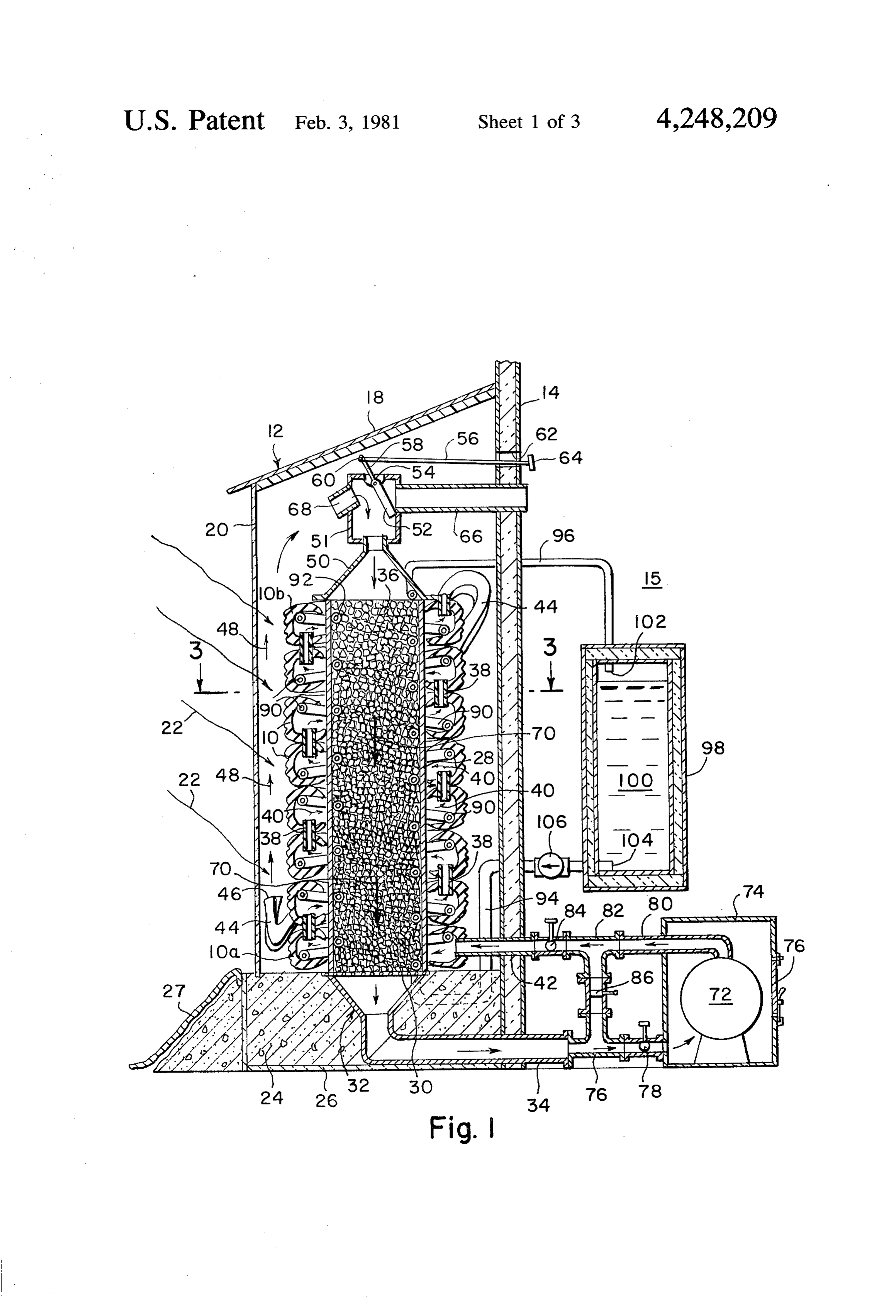
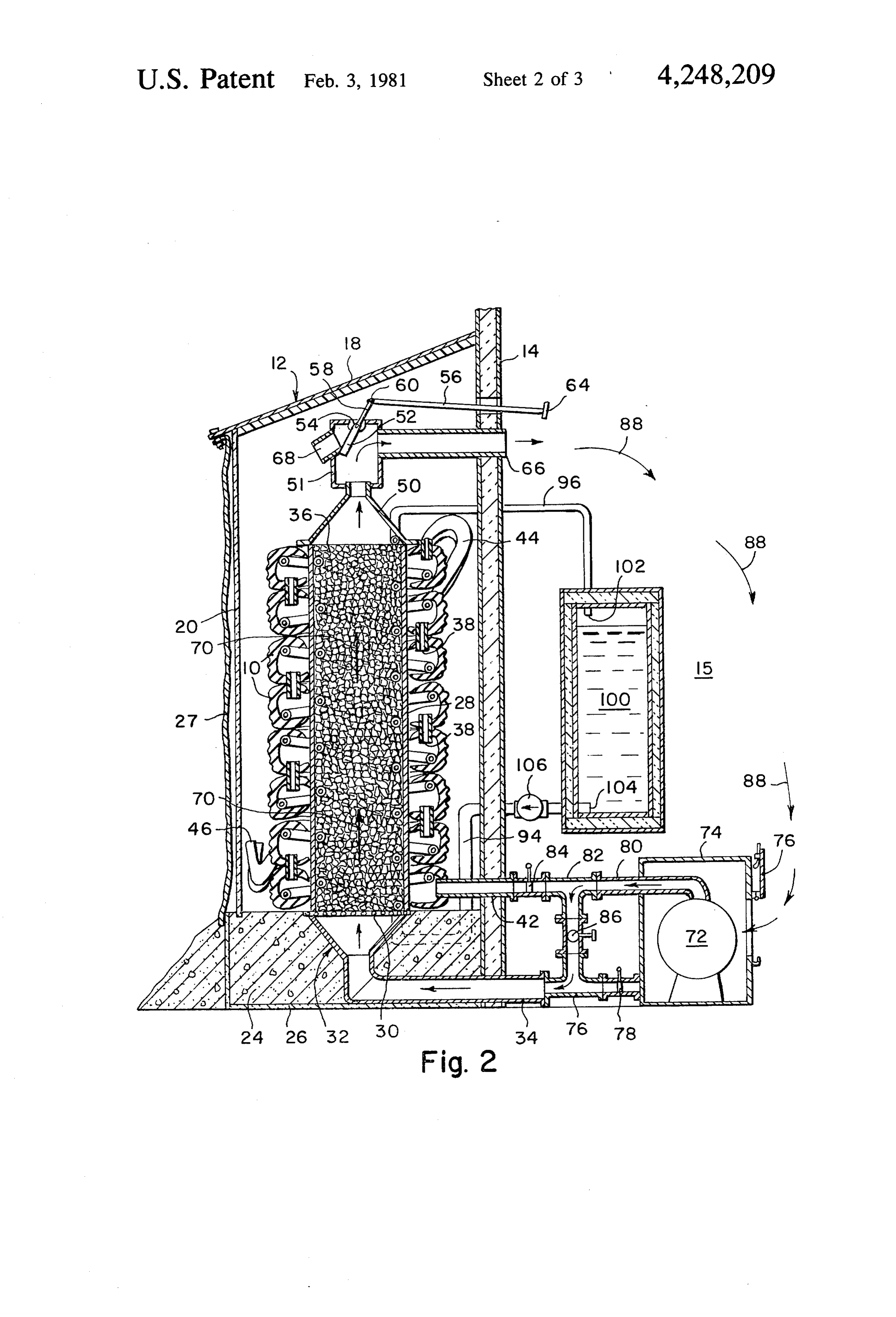
It is an object of the present invention to provide a The aforementioned and other objects, features and solar collection apparatus formed by a stack of gener ent advantages of the present invention will become appar ally toroidal, hollow, substantially black, elastomeric, 40 upon perusal of the following detailed description of vehicular tire-like members with conduit means cou the preferred embodiments of the invention when taken pling together the hollow interiors of the members of in conjunction with the appended drawing. the stack along an air or fluid path passing angularly and BRIEF DESCRIPTION OF THE DRAWING serially through the interiors of said members. FIG. 1 is a cross-sectional side elevational view of a It is further object of the present invention to provide 45 a stacked tire solar collector which includes a thermal first embodiment of the stacked-tire solar collector of energy storage medium in the center of the stack in the present invention with its associated parts posi which a recirculating air or fluid path is set up between tioned for absorbing solar radiant energy and transfer the members of the stack and the medium for transfer ring this energy to the center of the stack. ring heat from the stack to the medium. 50 FIG. 2 is a cross-sectional side elevational view of the It is yet another object of the present invention to first embodiment of the stacked-tire solar collector of provide a stacked tire solar collector with a thermal FIG. 1 but with its parts positioned for transferring heat energy storage medium at the center of the stack in from the center of the stack to a living space proximate conjunction with switchable damper means for setting the collector.
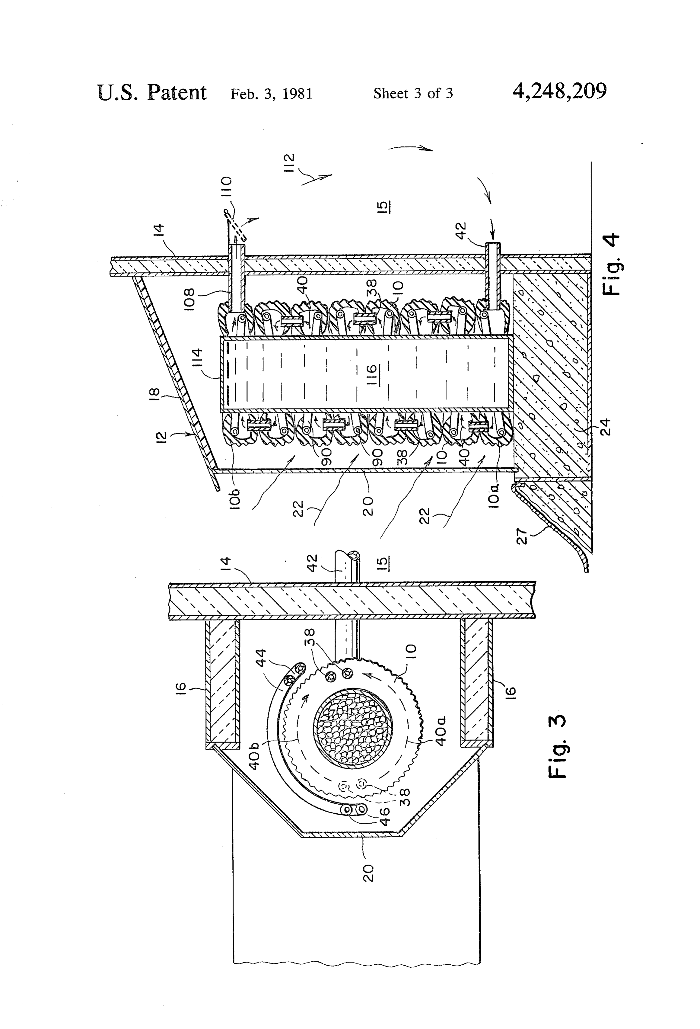
up either a recirculating air or fluid path between the 55 FIG. 3 is a downwardly looking cross-sectional view interiors of the tires and medium or between the me of the first embodiment, taken through the lines 3-3 in dium and a living space to be heated. FIG. 1; and
It is still another object of the present invention to FIG. 4 is a cross-sectional side elevational view of a provide a stacked tire solar collector, having a thermal second embodiment of the stacked-tire solar collector energy storage medium at the center of the stack with 60 apparatus of the present invention.
conduit means coupling together the tires and the me DETAILED DESCRIPTION OF THE dium in a manner that a recirculating air or fluid path is PREFERRED EMBODIMENTS set up serially through the interiors of the tires, through the medium and along the exteriors of the tires. Referring to FIGS. 1 through 3, the first embodiment 65 of the stacked-tire solar collector apparatus of the pres
SUMMARY OF THE INVENTION ent invention comprises a vertical stack of generally The aforementioned and other objects of the present toroidal, hollow, substantially black, elastomeric mem invention are satisfied by providing a vertical stack of bers which are preferable used vehicular tires 10 be 6 cause of their inexpensive availability and good solar 44 are directed downward to a point proximate the base energy absorption characteristics. The stack of tires 10, of the stack of tires 10 and in front of window 20, with is provided within an enclosure 12 which is conve open ends 46 of conduits 44 being upwardly directed. niently built against the thermally insulated southern This enables air from air path 40 after passing through wall 14 (in northern hemispheres) of a building or living the interior of tires 10 and out top tire 10b, to rise along space. 15 to which heat is to be supplied. Wall 14 forms path 48 which is directed along the exterior of tires 10 the rear wall of enclosure 12. In addition, the enclosure between the stack of tires and the window 20. The has thermally insulated sidewalls 16, a thermally insu rising air along path 48 picks up further heat from tires lated roof 18 and a southerly facing translucent window 10.
20 through which solar radiant energy 22 enters the O At the top of collar 23 is provided a downwardly enclosure and strikes the tires 10 thereby heating them. opening funnel-shaped duct 50 which is coupled to a Enclosure 12 is built upon a foundation 24 as of con rectangular shaped element 51 in which a planar crete, which is thermally insulated from the ground by damper 52 is pivotally mounted at 54. The movement of slabs of insulating material 26, such as foamed polysty damper 52 is controlled by a rod 56 which is pivotally rene. Also provided is an opaque and preferably reflect 15 mounted to a rod-like extension 58 of damper 52 at 60. ing curtain 27 which may be selectively positioned to Rod 56 passes freely through a hole 62 in wall 14 and uncover window 20 as in FIG. 1 for daytime, or cover terminates with a handle 64. When handle 64 is pushed window 20 as in FIG. 2 for evening. In the evening, to a position as shown in FIG. 1, damper 52 is posi curtain 27 reduces heat leakage from the stacked tires tioned to cover the opening of a duct 66 which passes 10, through window 20. Thermal insulation, such as 20 from element 51 through wall 14 and to uncover an aluminum jacketed fiberglass sheets (not shown) may be opening 68 in element 51 which faces window 20. In provided within enclosure 12, against wall 14 to reflect this position, air entering bottom tire 10a through duct radiant energy onto the stack of tires 10. 42, passes serially through tires 10 along path 40, out Each of the tires 10 is fitted sealably about an upright conduits 44, and upwardly from open ends 46, along cylindrical metal collar 28 which rests upon a rigid 25 path 48, through opening 68 into elements 51, down grating or mesh 30 carried by foundation 24. At the time wardly through funnel-shaped duct 50 and through a foundation 24 is poured, an upwardly opening funnel downward air path 70 through the column of rocks 36, shaped duct 32 is provided in the foundation positioned through funnel-shaped duct 32 and through output por under the grating 20. Duct 32 includes a cylindrical tion 34.
output portion 34 which is directed through the base of 30 The aforementioned air path including paths 40, 48 wall 14. Thus, duct 32 receives any downwardly di and 70 is maintained in a recirculating air path by means rected air flow through the center of collar 28 and of a centrifugal fan 72 or other suitable fan means, lo directs that air flow through output portion 34. The cated within the building defined by wall 14. Fan 72 is center of collar 28 is filled with a column of rocks 36 as located in an airtight box. 74, having a door 76 which a thermal energy storage medium. Rocks 36 are packed 35 may be opened. Output portion 34 is coupled to the loosely in order that vertical air flow through the col interior of box. 74 via a tee 76, and a damper element 78. umn can take place. Similarly, the duct 42 is coupled to the output port 80 of Preferably, flexible conduits 38, such as vacuum fan 72 by means of a tee 82 and a damper element 84. cleaner hose of about 1 inches in diameter, are passed The other branches of tees 76 and 82 are connected vertically through holes in the sidewalls of tires 10 for together by means of a damper element 86. As shown in serially coupling together the hollow interiors of the FIG. 1, with the damper elements 78 and 84 in an open tires 10. Each tire is coupled to the tire above at one state, the damper element 86 and door 76 in a closed location and to the tire below at another location ap state, the air emanating from output portion 34, passes proximately 180 degrees spaced apart. This is best un through fan 72 and is driven out duct 42 to maintain air derstood from an examination of FIG. 3 of the drawing 45 recirculation to transfer heat from tires 10 to the ther where at the upper sidewall of tire 10 a pair of side by mal energy storage medium comprising the column of side conduits is utilized for adequate air carrying capac rocks 36.
ity to couple to the tire above and at a location 180 When, as in the evening, it is desired to exchange heat degrees removed, another pair of side by side conduits from the rocks 36 to the interior 15 of the building 38, (shown in hidden line) are used to couple tire 10 to 50 defined by wall 14, as shown in FIG. 2, along an air path the tire below. As a result, two angular air paths 40a, 88 in the building directed from duct 66 to the box. 74, 40b are created through the interior of each tire 10 then handle 64 is pulled to reposition damper 52 to directed from the intersection of conduits 38 with the uncover the opening to duct 66 and to cover the open lower sidewall of each tire to the intersection of con ing 68. Also, the dampers 78 and 84 are closed and the duits 38 with the upper sidewall of each tire. Each of 55 damper 86 and door 76 are opened. This action sets up paths 40a, 40b is about 180 degrees in extent. As a conse an air flow from fan output 80, to tee 82 to tee 76 and quence of the provision of conduits 38 coupling to out portion 34. This air flow continues upward through gether the interiors of tires 10, there exists a first air path funnel-shaped duct 32 and up through the rocks 36, 40 which starts at the bottom tire 10a and passes angu along path 70, through funnel-shaped duct 50, and ele larly through each tire along paths 40a, 40b and serially 60 ment 51 into duct 66, along path 88 within living space from each tire to the tire above. Air path 40 is in heat 15 and through open door 76 into the box. 74 to fan 72. exchange relationship with the walls of tires 10. Additional heat storage capacity may be provided A conduit or pipe 42 passes radially through a hole in utilizing the hollow interiors of tires 10 by filling a the tread of bottom tire 10a to provide the start of air plurality of elongated, flexible thin-walled plastic or path 40. Conduit 42 also passes through wall 14. A pair 65 elastomeric tubes 90, of about 1 inch in diameter and of elongated, flexible conduits 44, as of the same charac about four feet in length, with a phase change material teristics as conduit 38, pass through the upper sidewall preferably having a heat of fusion in excess of 50 BTU of the top tire 10b to define the end of path 40. Conduits per pound and a melting point ranging between 75 and
Page 7scan →
120 degrees Fahrenheit, and thereafter sealing the ends It should be appreciated that the preferred embodi of each tube. The plastic utilized such as polyolefin ments of the present invention have been described in should include about 35% by weight of carbon black, particular detail. However, numerous modifications, metallic oxide, or metal flakes to render the wall of tube additions and omissions in these details are possible 90 thermally conductive. A separate one of tubes 90 is 5 within the intended spirit and scope of the invention. laid angularly directed within the toroidal hollow of For example, in the embodiment of FIGS. 1 through 3 each tire 10. Suitable phase change materials generally of the drawing, the collar 28 and column of rocks 36 consist of salt hydrates, such as sodium sulfate decahy might be replaced with an annular water tank which in drate, or their eutectics. Suitable compositions therefore turn might be coupled to pipes 94, 96. Furthermore, a including nucleating and homogenizing agents are de 10 liquid might be utilized, instead of air as a heat transfer tailed in U.S. Pat. No. 3,986,969 to Maria Telkes medium in the "air' paths previously referred to. granted Oct. 19, 1976. Other phase change materials Hence, the term "fluid" is intended to encompass both such as waxes are known but not generally preferred liquid and gaseous heat transferW media. because of flammability. Further, other, configurations 5 What is claimed is:
of holders for the phase change material, which are 1. A solar collector apparatus comprising: adaptable to the hollow toroidal interiors of tires 10 and a vertical stack of coaxially aligned generally toroidal which are configured so as not to unduly obstruct the hollow, substantially, elastomeric, vehicular tire air path 40 may be used. It will be appreciated that as like members for absorbing and being thereby heated by solar radiant energy;
the tires 10 are heated, this heat is transferred by con 20 conduit duction and convection, to and stored in the phase means intercepting the members of said stack change material filled tubes 90 and the air flow along 40 at angularly spaced apart locations, said conduit extracts this heat along with heat from the walls of tires means being directed for serially coupling together O. the hollow interiors of the members of said stack, The solar collector of the present invention may also 25 said conduit means defining a first fluid path pass be used for heating water by providing an elongated ing angularly and serially through the hollow inte rigid pipe 92 as of copper, coiled in a vertically directed riors of the members of said stack in heat exchange helix within the bed of rocks 36. Pipes 94, 96, coupled to relationship with the interiors of said members; top opposite ends of pipe 92, pass through wall 14 and are and bottom portions of said conduit means being at directed to a thermally insulated tank 98 for the water opposite extremes of said first fluid path, said con duit means intercepting each member at two said 100 being heated. Pipe 96 is directed to an inlet 102 at locations which are angularly spaced apart about the top of tank 98 and pipe 94 is directed to the outlet 180 degrees, whereby said first fluid path includes 104 of the tank 98 and an electric pump 106 in series two angular fluid paths through the hollow interior with pipe 94 continually recirculates the water 100 of each member, each of said two angular fluid between the helical pipe 92 and the tank 98 whereby the 35 paths being about 180 degrees in extent; water is heated by the rocks 36. a heat storage medium in the center of said stack, said The stacked tire solar collector of the present inven heat storage medium being configured to define a tion, when being heated by incident solar radiant en second fluid path through the center of said stack ergy, produces a thermal gradient vertically along the in heat exchange relationship with said medium; stack which tends to drive air generally upward along 40 fluid path defining means respectively coupling the path 40. This effect is taken advantage of in a simplified bottom and top ends of said medium to said bottom embodiment of the stacked tire solar collector of the and top conduit means portions to define a first present invention as illustrated in FIG. 4 of the drawing. recirculating fluid path including the first and sec Therein, the stack of tires 10 is provided in a similar ond fluid paths; and enclosure 12. The tires 10 are coupled in the manner 45 impeller means in series with said fluid path defining previously described by conduits 38 to provide the air means for driving fluid through said first recircu path 40 passing angularly and serially through the inte lating fluid path, whereby heat from said members riors of the tires. However, the duct 42 which is di is transferred to said medium. rected radially through the tread portion of bottom tire 2. The apparatus of claim 1, further comprising a 10a, forms a port for receiving air from the building or 50 third fluid path through a space, proximate said mem living space 15 defined by wall 14. Additionally, a duct bers, to be heated and wherein said fluid path defining 108 passes radially through tread portion of top tire 10b means includes switchable means for selectively either and passes through wall 14. Duct 108 terminates within placing said impeller means in series with said first recir the building with an adjustable register 110 for selec culating fluid path or for placing said impeller means in tively closing off duct 108. When the register 110 is 55 series with a second recirculating fluid path which in open, heated rising air along path 40 through the interi cludes said second and third fluid paths. ors of tires 10, exits duct 108 at register 110 and flows 3. The apparatus of claim 1, wherein said fluid path downward along a path 112 within the living space 15 defining means defines said first recirculating fluid path to duct 42 where it returns to the bottom tire 10a, Thus, in a manner that over a portion of said first recirculating a continuous air circulation is produced along the paths 60 fluid path, fluid flows generally vertically along and in 40 and 112 which transfers heat from the tires 10 to the contact with the exterior of said stack for additional living space 15. heat exchange.
In this embodiment, the stack of tires 10 is preferably 4. The apparatus of claim 1, further comprising recir fitted sealably about a vertically directed sealed cylin culating liquid heat exchange means in heat exchange drical metal tank 114 containing water 116 for thermal 65 relationship with said medium and with a space, exter energy storage. The tubes 90 containing phase change nal of said stack, to be heated.
material are also conveniently utilized within the interi 5. The apparatus of claim 1, further comprising a ors of tires 10, thermal energy storage medium within the hollow inte 8 rior of each member of said stack, said medium being respectively coupling the bottom and top ends of said configured and contained so as to enable fluid flow medium to said bottom and top conduit means portions along said first fluid path angularly through the hollow to define a first recirculating fluid path including the interiors of said members. first and second fluid paths and further including impel 6. A solar collector apparatus comprising: ler means in series with said fluid path defining means a vertical stack of generally toroidal, hollow, substan for driving fluid through said first recirculating fluid tially, elastomeric, vehicular tire-like members for path, whereby heat from said members is transferred to absorbing and being thereby heated by solar radi said medium.
ant energy; and 8. The apparatus of claim 7, further comprising a conduit means intercepting the members of said stack 10 third fluid path through a space, proximate said mem at angularly spaced apart locations, said conduit bers, to be heated and wherein said fluid path defining means being directed for serially coupling together means includes switchable means for selectively either the hollow toroidal interiors of the members of said stack, said conduit means defining a first fluid path culatingsaid placing impeller means in series with said first recir fluid path or for placing said impeller means in passing angularly and serially through said hollow 15 series with a second recirculating fluid path which in toroidal interiors of the members of said stack in heat exchange relationship with the interiors of cludes 9.
said second and third fluid paths.
The apparatus of claim 7, wherein said fluid path said members; top and bottom portions of said defining means conduit means being at opposite extremes of said in a manner thatdefinesover a said first recirculating fluid path portion of said first recirculating fluid path, fluid flows generally vertically along and in said conduit means intercepting each member at two contact with the exterior of said stack for additional said locations which are angularly spaced apart heat exchange.
about 180 degrees, whereby said first fluid path includes two different angularly spaced apart, an 10. The apparatus of claim 7, further comprising re gularly directed fluid paths through the hollow 25 circulating liquid heat exchange means in heat exchange toroidal interior of each member, each of said two relationship with said medium and with a space, exter angularly directed fluid paths being about 180 de nal of said stack, to be heated.
grees in extent. 11. The apparatus of claim 7, further comprising a 7. The apparatus of claim 6, wherein the members of thermal energy storage medium within the hollow inte said stack are aligned coaxially, and further comprising 30 rior of each member of said stack, said medium being a heat storage medium in the center of said stack config configured and contained so as to enable fluid flow ured to define a second fluid path through the center of along said first fluid path angularly through the hollow said stack in heat exchange relationship with said me toroidal interiors of saidk members. dium, and further comprising fluid path defining means k s
Provenance
- Collection
- Patents citing this work
- Pages
- 8
- Method
- pdftotext (the PDF's own text layer) + pdftoppm 300dpi page scans
- Patent office record
- patents.google.com →
- Source
- Google Patents citing-documents table
- Assignee
- Wasserman Kurt J
- Published
- 1981-02-03
- Transcribed from
- patentimages.storage.googleapis.com →