

patent · US4257479A
Heat exchanger and drain down for solar collector
24 March 1981
Text
Page 1bibliographic recordscan →
United States Patent (19)
Newton
(54) HEAT EXCHANGER AND DRAIN DOWN
FOR SOLAR COLLECTOR
Inventor: T. Lawrence Newton, Atherton,
Calif.
Assignee: Sunburst Solar Energy Corp., Menlo
Park, Calif.
Int. Cl. ............................ F28D 7/12; F24J 3/02 52 U.S. C. .......................... . . . . . . . . . . 165/156; 126/420;
1,951,403 3/1934 Goddard .............................. 126/435 2,324,257 7/1943 Ekert ............ ... 165/156 2,425,669 8/1947 Brock ....... ... 165/156 3,100,523 8/1963 Marrujo ... ... 165/163 3,482,625 12/1969 Bray ......... ... 165/163 4,067,314 1/1978 Bollefer ........ ... 126/435 4,082,143 4/1978 Thomason ............................ 126/435 4,083,490 4/1978 Cunningham et al. ... 126/437 4,108,160 8/1978 Harper ................................. 126/420
4,130, 10 12/1978 Bottum ................................. 126/435 4,138,996 2/1979 Cartland ............................... 126/420 Primary Examiner-James C. Yeung
Assistant Examiner-Daniel O'Connor
Attorney, Agent, or Firm-Julian Caplan
A solar collector has a liquid system independent of a household hot water heater system, the two systems transferring heat in a heat exchanger. The heat ex changer has an open top inner tank enclosed in a closed outer tank, a coil connected to the hot water tank sys tem circulates under main pressure in a coil in the annu lar space between the inner and outer tanks. Liquid from the collector enters at the bottom of the annular space, flows upward around the coil and overflows the top of the inner tank. A pump draws liquid from the bottom of the inner tank for circulation through the solar collector system. The liquid in the collector sys tem drains by gravity into the inner tank at any time that the collector circulating pump is not operating, thus providing freeze protection during all normal opera tions and also at such time that a power failure may OCC.
7 Claims, 3 Drawing Figures
Drawings
Page 2drawing sheetscan →
Page 3scan →
HEAT EXCHANGER AND DRAIN DOWN FOR likely to damage the collector 11, the power source is likely to be interrupted. Annually, great damage occurs
SOLAR COLLECTOR in such instances.
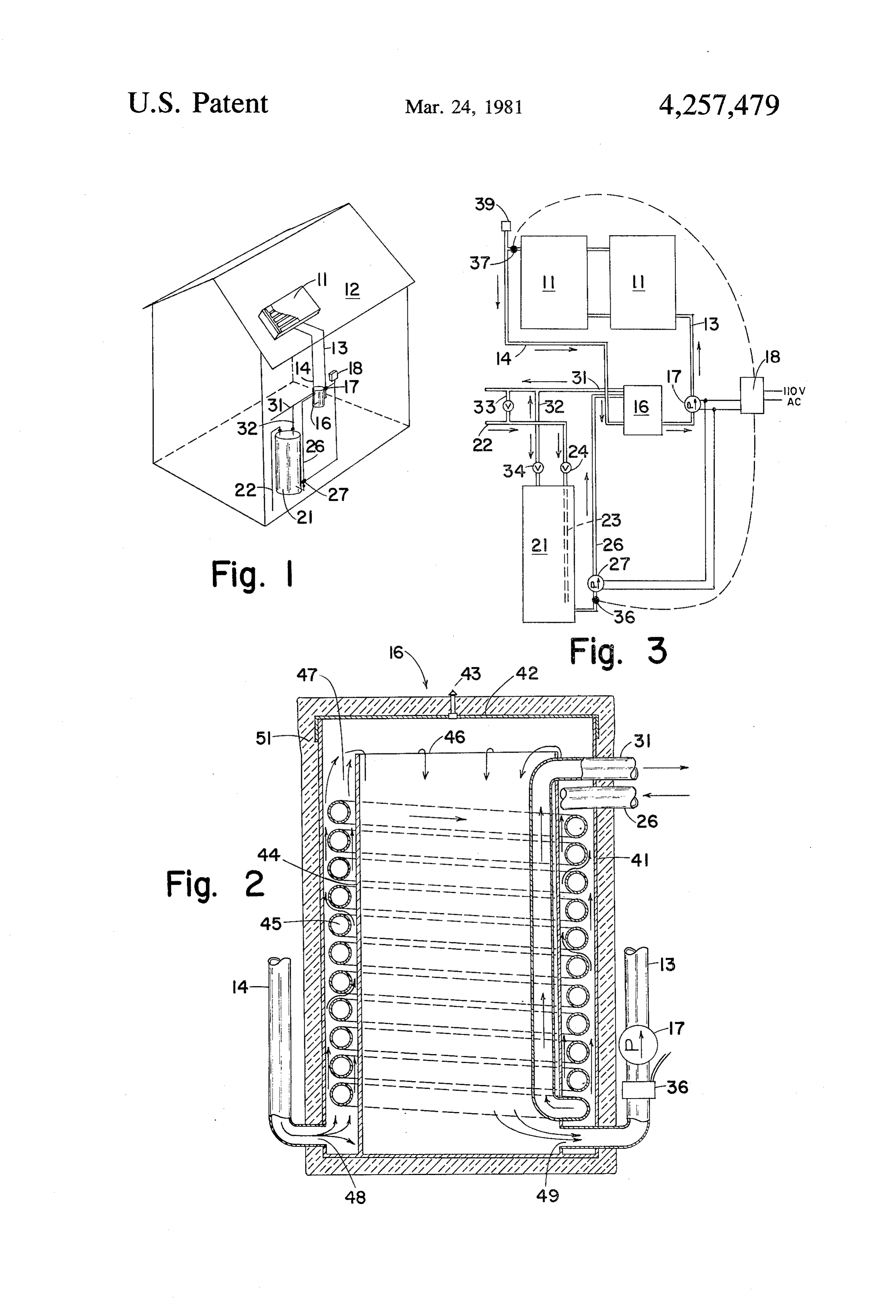
This invention relates to a new and inproved heat 5 used A hot water heater 21 of well known construction is in the system of the present invention, it being exchanger and drain down for solar collectors. understood that the heater 21 supplements the solar Solar collectors are commonly used in exposed areas collector 11 in cold weather, and the collector 11 sup where there is a definite hazard of freezing. Since the plements the heater 21 in periods of sunshine, all as well internal constructions of such panels contain tubes, understood in this art. Thus, water under main pressure great damage may occur. The present invention pro 10 from main 22 is directed into the tank of heater 21 vides a tank into which the liquid in the solar panels through shut-off valve 24. The outlet 26 of the tank of may drain by gravity whenever the collector pump is inactivated by normal operation or power failure. In heater 21 is connected to a pump 27 also controlled by normal usage, the device performs its heat exchange changer 16. controller differential 18. Pipe 26 leads to heat ex
Outlet pipe 31 extends from the heat ex function under appropriate thermal controls depending 15 changer 16 to the household water system, swimming upon whether the liquid in the solar panels or the hot pool or whatever location for which the system is de water is at a higher temperature. signed. Bypass pipe 32 interconnects pipe 31 with the Accordingly, the present invention provides in a tank 21 and is controlled by a shut-off valve 34. Water single device a heat exchanger for normal operation of may circulate in either direction through the bypass 32. a solar heating system which is used in combination 20 There is a further bypass and a temperature controlled with a hot water heating system, but in emergencies valve 33 between the pipes 31 and 22 to insure that the occasioned by freezing temperatures and particularly water flowing into the hot water system of the resi when there is an electric power failure (which some dence is not too hot.
times coincides with freezing temperatures) provides a In a commercially available system, a sensor 36 is convenient tank for gravity drainage of the liquid in the 25 installed in pipe 26 near the tank of heater 21, and a collector. second sensor 37 is installed at the discharge of the A further feature of the invention is the fact that by collector 11. Sensors 36 and 37 are electrically con the use of the heat exchanger the liquid in the solar nected into differential controller 18 and determine collector is maintained separate from the water in the actuation of pumps 17 and 27. A vacuum breaker 39 hot water system. 30 may be installed at the outlet of sensor 11 in accordance Another means of preventing freezing damage to with common commercial practice. solar collectors is to use an anti-freeze solution in the Directing attention now to the heat exchanger 16 collector system. Unfortunately, many such liquids are shown in detail in FIG. 2, it will be observed that there toxic and there is always a danger that in the heat ex is an outer tank 41 having a removable cover 42 sup changer there will be contamination of the potable 35 plied with a vent 43. Inner tank 44 is of lesser diameter water supply from the toxic fluids. The present inven than tank 41 and centrally disposed therein. Tank 44 has tion makes it possible to use water in the collector sys an open top 46 spaced below cover 42, and there is an tem and to eliminate the use of toxic anti-freeze mate rial, thereby reducing possibility of contamination of annular coil of space 47 between the tanks 41 and 44. A helical pipe 45 is installed in the annular space 47, one the water supply. 40 end of coil 45 being connected to pipe 26 and the other Other objects of the present invention will become to pipe 31. Pipe 14 discharges through port 48 into the apparent upon reading the following specification and bottom referring to the accompanying drawings in which simi accepts of the annular space 47. Inlet port 49 for pipe 13 liquid from the bottom of tank 41. Insulation 51 lar characters of reference represent corresponding of conventional type is lapped around the outside of parts in each of the several views. 45 heat exchanger 16.
In the drawings: In normal usage of the system, liquid (preferably FIG. 1 is a schematic perspctive view showing a water) is forced by pump 17 up pipe 13 through the typical installation of the present invention in a solar collector panels 11 and out through pipe 14. The water heated-hot water heating combination. is discharged from pipe 14 through the port 48 into the FIG. 2 is an enlarged sectional view through the heat 50 annular space 47 and flows up the annular space, ex exchanger. changing heat with the water in the coil 45. The water FIG. 3 is a schematic piping and wiring diagram of in the annular space 47 then overflows the top edge 46 the installation of FIG. 1. of the inner tank 44. At the bottom of the tank 44 it is One or more solar collectors 11 singly or in series or picked up by the discharge port 49 and recirculated by other combinations are located in an area exposed to 55 pump 17 through the pipe 13. Meanwhile, water from sunlight but also, on occasions, exposed to freezing the tank of the water heater 21 is pumped by pump 27 weather. Typically, such panels 11 may be installed on through the pipe 26 down through the coil 45 and up the roof 12 of a residence. The liquid which is circulated through the pipe 31 to the household water system, through the panels 11 may be water, there being a re swimming pool, etc.
turn pipe 13 which returns cooler water to the panel 11 In the event of a failure of power or the normal oper and an outlet pipe 14 which transmits hot water from ation of the controller 18 which inactivates the pumps the panel 11 to a heat exchanger 16, hereinafter de 17 and 27, all of the water in the collector 11 drains scribed in detail. After passing through the heat ex down through pipe 14, the vacuum breaker 39 facilitat changer, the water is pumped by means of pump 17 ing such drainage. The capacity of tank 44 is such as to through the return pipe 13. A differential controller 18, 65 accommodate all of the water in the solar panels 11. which is commercially available and well understood in Hence, the tank 44 may be filled with water and the this art, is connected to a power line and controls the panels 11 completely drained. Normal solar operation pump 17. Unfortunately, when freezing weather is causes the controller 18 to reactivate pump 17 and 4 pump 27 and to pump water from the tank 44 back 3. Apparatus according to claim 1 which further through the collector 11 and to circulate water from the comprises a solar collector having an outlet and an inlet hot water tank 21 thru heat exchange coil 45. In other connected to said first and second ports, respectively, respects, the system illustrated in FIG. 3 operates the and means for circulating said second liquid from said same as conventional solar collector-hot water heated second port, through said collector and back to said first combinations. port.
The presently preferred embodiment for use of the 4. Apparatus according to claim 3 in which said solar heat exchanger has been illustrated and described. whereby, isupon collector at a higher elevation than said casing,
However, other uses for the combined heat exchanger 10 liquid to operate,failure liquid of said means for circulating in said solar collector drains by and drain down are contemplated. gravity down to said first port, up said gap and through What is claimed is:
1. A heat exchanger and drain down comprising a said to opening into said tank, said tank having a capacity accommodate substantially all the liquid in said col casing, a tank within said casing and of lesser cross-sec lector.
tion than said casing so that a gap exists between said 15 5. Apparatus according to claim 3 in which said heat tank and said casing, said tank having an opening at its exchange top communicating with said gap, a first port at the ports and means has heat exchanger inlet and an outlet which further comprises a water heater hav bottom of said casing communicating with said gap, a ing an heater outlet and heater inlet and piping intercon second port at the bottom of said tank, and heat ex necting said heater outlet and heat exchanger inlet port change means for circulating a first liquid for thermal and said heat exchanger outlet port and said heater inlet. exchange with a second liquid circulating from said first 6. Apparatus according to claim 5 in which said heat port upward through said gap, through said opening exchanger means comprises a helical coil of tubing into said tank and out said second port, said heat ex located in said gap.
change means being located in said gap, said heat ex 7. Apparatus according to claim 5 in which said change means comprising a helical coil of tubing, said 25 heater has a tank under water main pressure and a sepa first port, said gap, said tank and said second port com rate circulating pump, whereby warm water in said tank prising a normally closed second liquid system isolated circulates through said heat exchange means to warm from said first liquid. liquid in said tank which has drained from said collec 2. Apparatus according to claim 1 in which said gap tOr. k is k k k is annular. 30
Provenance
- Collection
- Patents citing this work
- Pages
- 4
- Method
- pdftotext (the PDF's own text layer) + pdftoppm 300dpi page scans
- Patent office record
- patents.google.com →
- Source
- Google Patents citing-documents table
- Assignee
- Sunburst Solar Energy Corp.
- Published
- 1981-03-24
- Transcribed from
- patentimages.storage.googleapis.com →