

patent · US4258697A
Pneumatic collection, storage and transfer of solar heat
31 March 1981
Text
Page 1bibliographic recordscan →
United States Patent (19)
Flagg
(54) PNEUMATIC COLLECTION, STORAGE AND
TRANSFER OF SOLAR HEAT
76 Inventor: Rodger H. Flagg, 1415 Lynn Ave.,
Fort Wayne, Ind. 46805
Int. Cl.................................................. F24J 3/02 52 U.S. Cl. .................................... 126/430; 126/400;
2,907,318 10/1959 Awot ................................... 126/438 3,987,786 10/1976 Keyes et al. ... ... 126/400 3,997,108 12/1976 Mason ........ ... 126/422 4,061,267 12/1977 Lof ....................................... 126/419 4,086,909 5/1978 Lyon .................................... 126/432 4,088,266 5/1978 Keyes ................................... 126/430 4,129, 116 12/1978 Kent...................................... 126/429 4,151,830 5/1979 Crombie ............................... 126/450 4, 160,443 7/1979 Brindle et al. ....................... 126/426 4,182,307 1/1980 Brindle et al. . ... 126/426 Primary Examiner-James C. Yeung
Attorney, Agent, or Firm-Rodger H. Flagg
The collection, storage and transfer of solar heat by pneumatic means includes: a solar collection system; a heat storage system; and a means for selectively direct ing air through the solar collector, the heat storage, and the point of use. The solar collection system includes a first chamber of convex, curvilinear shape covered with a light-transmissive material, and positioned to receive sunlight. A series of second chambers is formed beneath the first chamber by light-transmissive material located above and below a series of inclined ducts through which air from the first chamber is directed. Each duct receives air from the upper portion of the preceding secondary chamber and redirects the air into the lower portion of the next succeeding secondary chamber.
After passing through the entire series of secondary chambers, the heated air is directed into a third con cave, curvilinear-shaped chamber located beneath the series of second chambers. The concave, curvilinear surface is made reflective so that sunlight passing through all three chambers strikes the reflective surface and is redirected back through the three chambers to additionally heat the air therein.
16 Claims, 11 Drawing Figures
Drawings
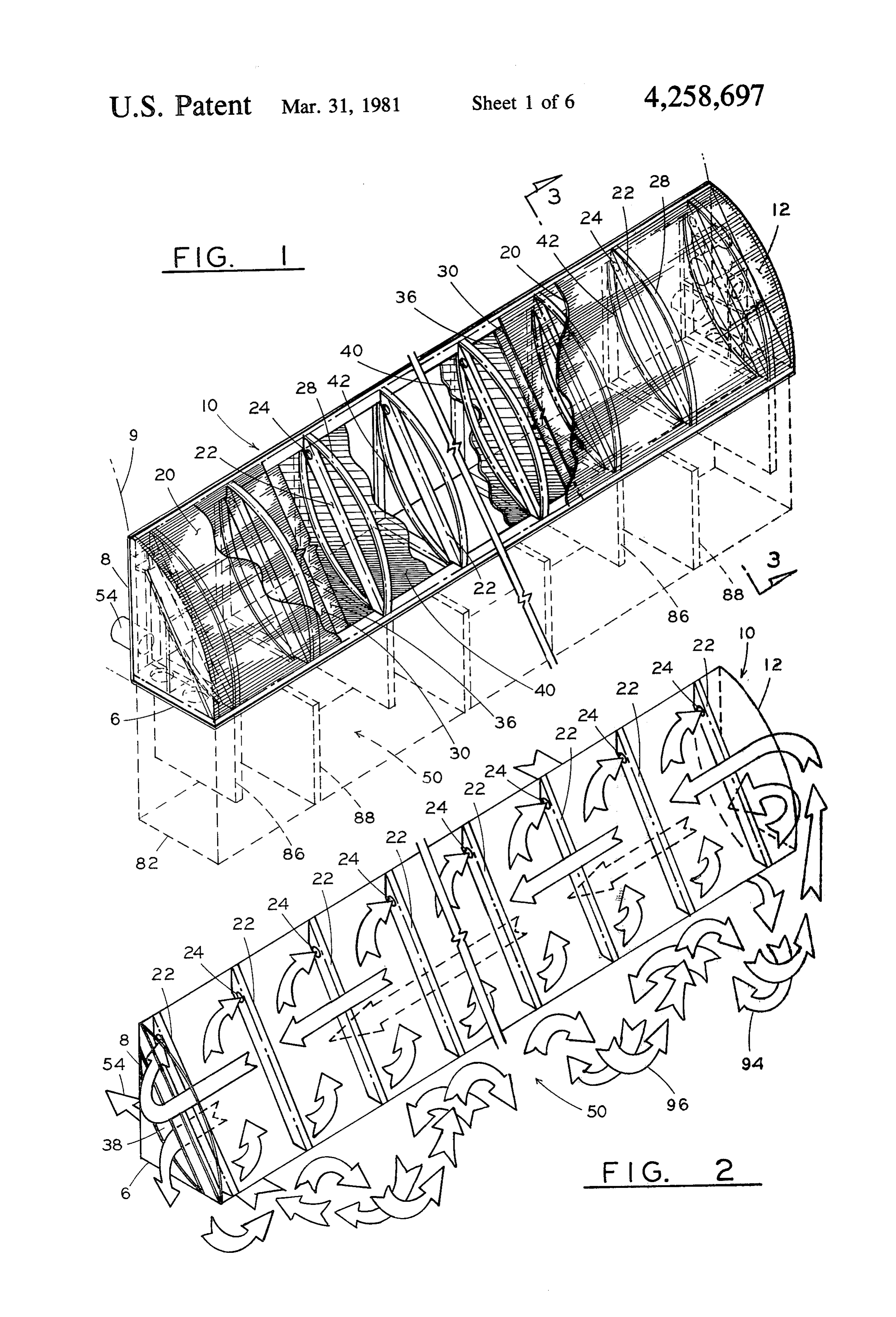
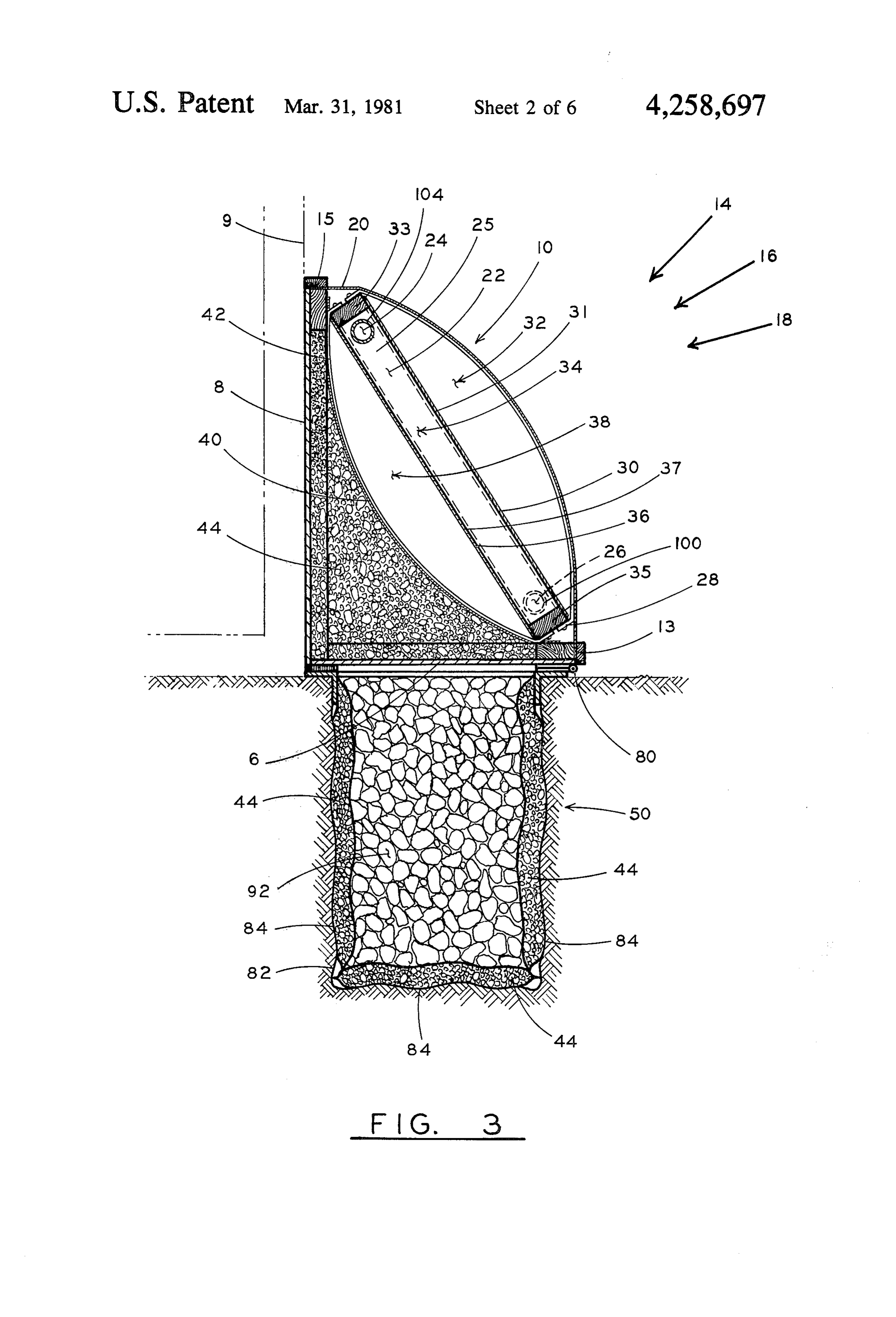
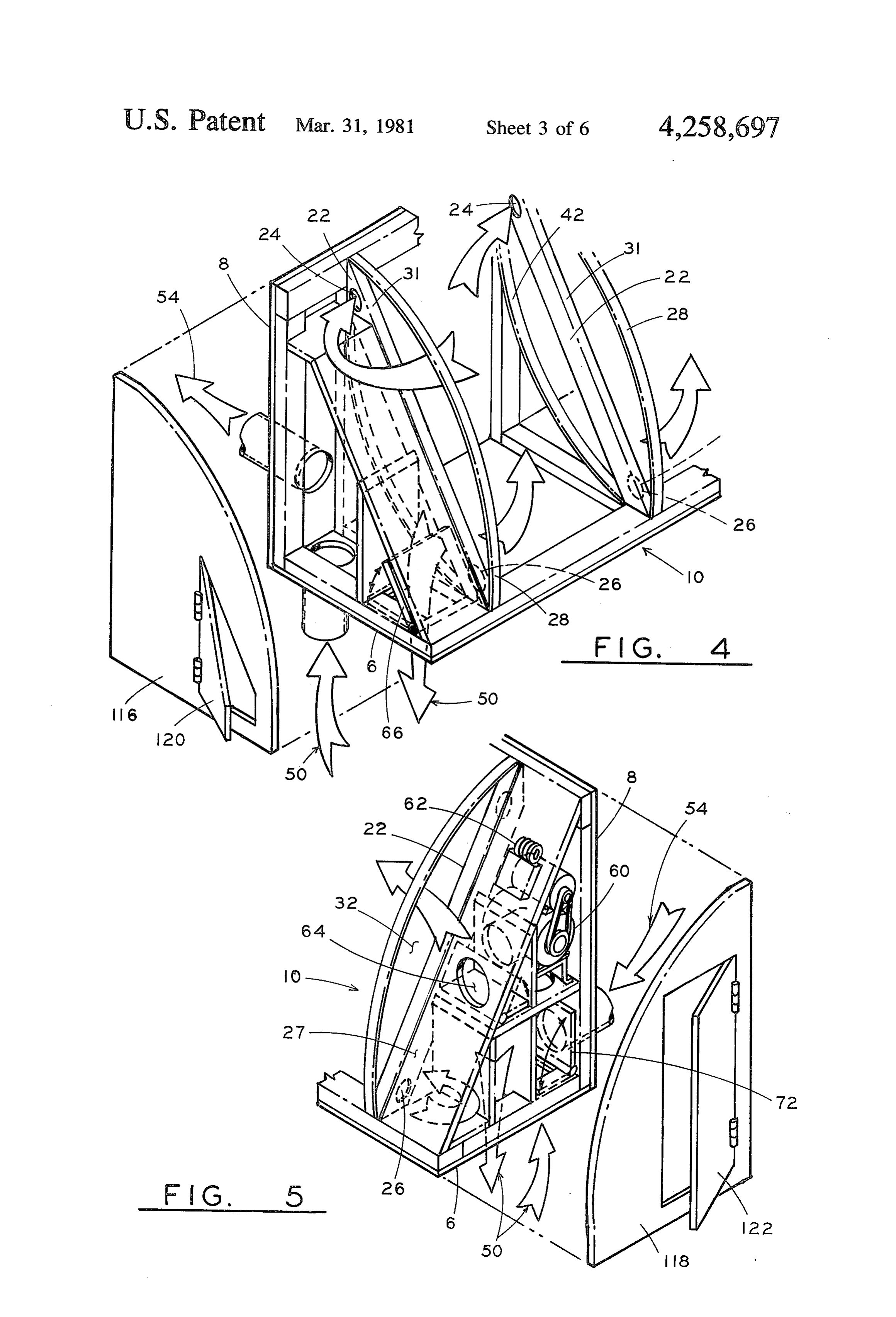
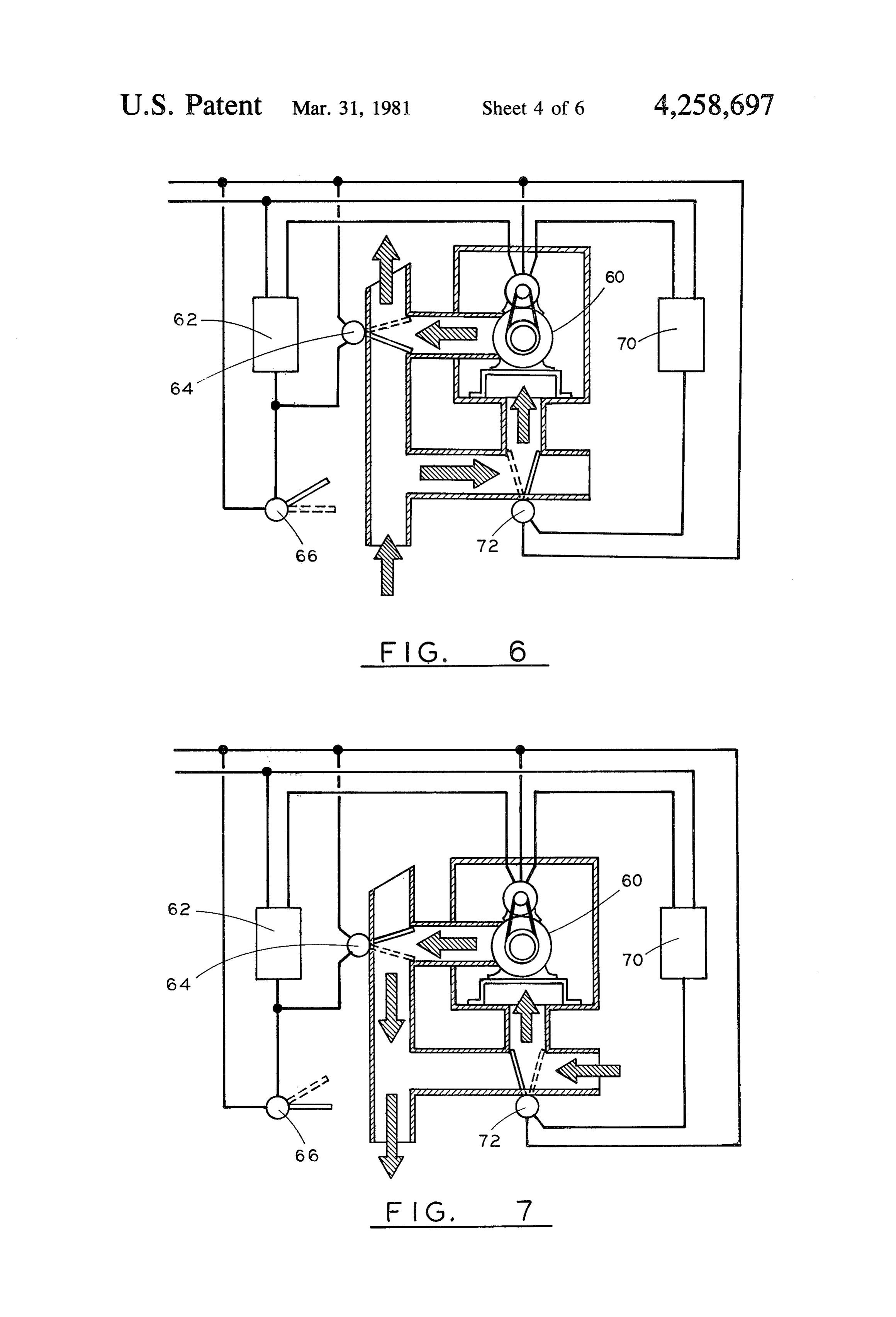
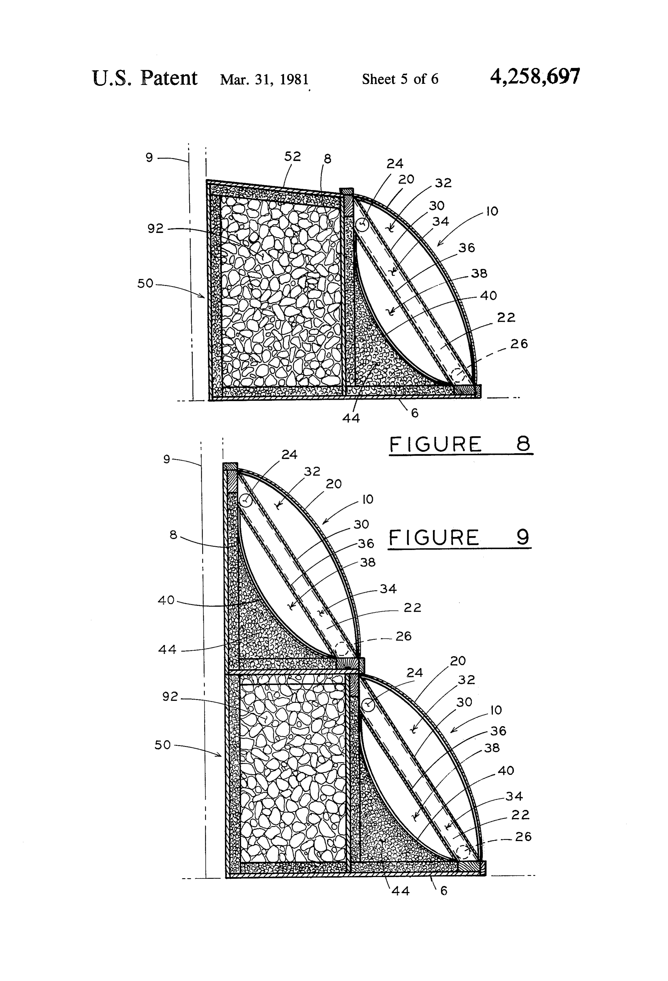
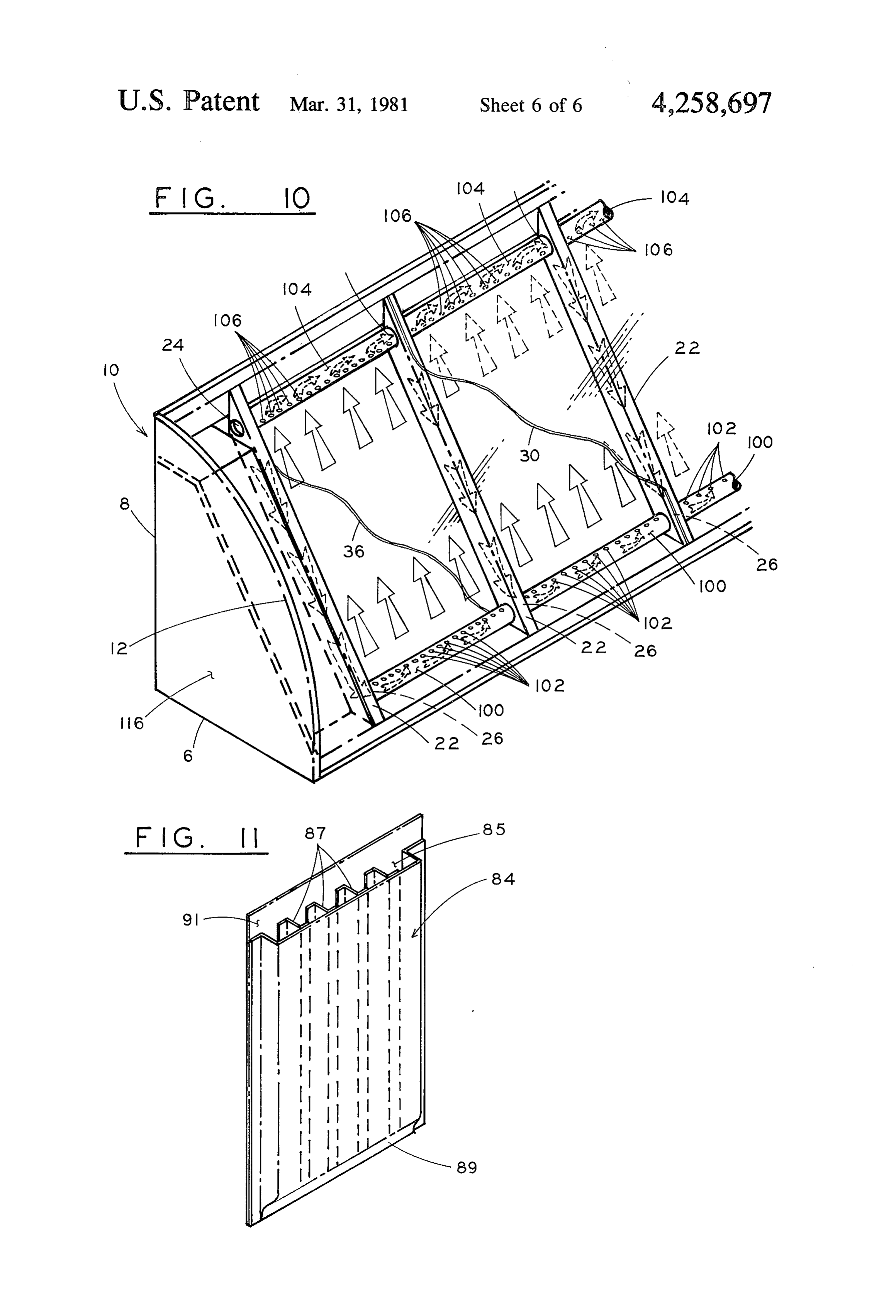
FIG. 2 shows the routing of air through the solar to equally distribute the air throughout each series of collection and heat storage apparatus. Note that air secondary chambers 34 without creating a back pres from the point of use travels through the heat storage sure of air in the system.
Page 2drawing sheetscan →
Page 3drawing sheetscan →
Page 4drawing sheetscan →
Page 5drawing sheetscan →
Page 6drawing sheetscan →
Page 7drawing sheetscan →
Page 8scan →
individually controlled gate valves serve to selectively
PNEUMATIC COLLECTION, STORAGE AND route the air through the system. TRANSFER OF SOLAR HEAT Other objects and advantages of this invention will become more apparent when viewed in light of the
BACKGROUND OF THE INVENTION 5 accompanying specification and drawings. Numerous attempts have been made to invent a de OBJECTS OF THE INVENTION pendable, reliable and economic system for collecting and storing the sun's heat. These systems can be broken One object of the present invention is to provide a down into two major types: passive and active systems. 10 new and improved method and apparatus for the pneu Passive systems function without the use of external matic collection, storage and transmission of heat gener energy. While these systems have the advantage of not ated from sunlight.
requiring an external energy supply, they are inferior to It is also an object of this invention to provide a com active systems with regard to their capacity to convert pact, self-contained solar heating system which can be sunlight to heat, and to adequately store and transfer the 15 installed externally to a new or existing building to heat as it is needed at the point of use. provide heat from the sun to a point of use within the Active systems for the collection of heat from sun building.
light can be divided into two major types: liquid sys It is another object of this invention to provide a low tems, and pneumatic systems.
Liquid systems have the advantage of obtaining exteriorlysolar profile, collection system which may be located greenhouse, and provide for heat collec slightly greater conversion rates of heat from solar 20 tion from the sun during the day while the greenhouse energy. However, liquid systems require greater invest is also heated by the sun; and provide additional heat to ments in terms of apparatus and maintenance. They the must be protected against freezing in colder climates. A whengreenhouse the from the heat storage media at night, greenhouse is not collecting heat from the leak in a liquid system can inactivate the entire system, St.
and may flood the surrounding area. 25
It is another object of the present invention to pro
Pneumatic systems, of which this invention is one, have several major advantages: the apparatus may be vide which three chambers through which the air must travel, serves to buffer the increasingly heated air from simple, easily manufactured and assembled, and provide the atmosphere and provide three times the quantity of reasonably high conversion of sunlight to heat. A leak air exposed to sunlight in a given collector area. in a pneumatic system, while reducing efficiency, nei 30 ther damages the surrounding environment nor requires It is a further object of this invention to provide for the system to shut down. increased storage capacity of the heat from the solar collector, so that the heat may be stored during daylight
SUMMARY OF THE INVENTION and used when the sun is no longer shining. The solar collection system has a convex, curvilinear 35 It is a further object of this invention to provide a shape positioned to receive sunlight, a horizontal base readily assembled solar collector system in kit form and a vertical rear support. The convex, curvilinear which may be readily installed next to a new or existing shape is covered with a light-transmissive material. A building.
series of elongated diagonal ducts are positioned be It is a further object of this invention to direct the air tween the top of the rear vertical support and the front from the solar collector to the heat storage or the point of the horizontal base support. of use through a single blower in such a way that the air A first chamber is formed between the outer, light travels through the heat storage apparatus in opposite transmissive sheet and a second light-transmissive sheet directions.
located on the upper surface of the series of ducts. A It is a further object of this invention to utilize bulk third light-transmissive sheet is located beneath the 45 materials (from local sources) while providing other ducts, forming a series of secondary chambers. Within materials in kit form, to reduce the costs of transporta each duct is an inlet located near the top and an outlet tion and minimize costs.
located near the bottom on the opposite side of the duct. These and other objects of this invention will become A concave, curvilinear, reflective surface forms a apparent to a person skilled in the art as that person third chamber beneath the series of secondary cham 50 reads the following drawings, specifications and claims. bers. This chamber redirects the air passing from the DESCRIPTION OF THE DRAWINGS series of secondary chambers across the entire length of the solar collector into the heat storage media, or to the FIG. 1 is a perspective view of the solar collection point of use. system showing the three chambers sectioned for ease Heat storage is located in proximity to the solar col 55 of presentation, with the heat storage system located lection system, either beneath or behind the solar col beneath the solar collection system; lector. FIG. 2 is a schematic view of the air flow within the Sectioned bags may be filled with particulate insulat solar collection system showing the routing of air ing material and used to insulate the heat storage sys through all three chambers and heat storage as well as tem. to-and-from the point of use; A single air pump has been adapted to selectively FIG. 3 is a cross sectional view taken through lines route air from the heat storage to the solar collector; 3-3 in FIG. 1 which shows a cross sectional view of from the point of use to the heat storage; or from the the solar collection system and heat storage where the point of use to the solar collector. The flow of air heat storage system is located beneath ground; through the heat storage medium is reversed, so that air 65 FIG. 4 is an exploded, isometric view of one end of traveling from the collector into the heat storage me the solar collection system showing the routing of air dium travels in opposite directions to air directed from from one chamber to the next and to-and-from the heat the point of use into the heat storage medium. Two storage;
Page 9scan →
FIG. 5 is an exploded, isometric view of the opposite ond light transmissive sheet 30, secured to the upper end of the solar collection system showing the routing portion of the diagonal ducts 22. of air from the point of use or heat storage, to the solar A series of second chambers 34, are formed between collector, or from the point of use through the blower the series of diagonal ducts 22, by a third light transmis to the heat storage; 5 sive sheet 36 adapted to be secured to the lower portion FIG. 6 is a schematic view of blower and associated 37 of the series of diagonal ducts 22.
duct system showing temperature-responsive means The light transmissive sheets 30,36 may be secured to controlling gate valves which act to selectively direct the diagonal ducts by adhesive tape, glue, screws, riv the air from heat storage through the blower and to the ets, or other conventional fastening means. solar collector; W 10 A third chamber 38 is formed between the third light FIG. 7 is a schematic view of the blower and associ transmissive sheet 36 and a concave, curvilinear light ated ductwork showing temperature-responsive means reflective material 40.
selectively positioning gate valves to direct the air from In the preferred embodiment, a series of concave ribs the point of use through the blower and into the heat 42, span from the upper portion of the rear vertical storage system; 5 support 8, to the forward portion of the horizontal base FIG. 8 is a cross sectional view of the solar collection 6. These concave ribs 42 serve to maintain the position system with the heat storage located behind the solar of the concave, curvilinear light-reflective material 40. collection system; Insulating material 44, is located between the hori FIG.9 is a cross sectional view of the solar collection Zontal base 6, the rear vertical support 8, and the con system and heat storage wherein two solar collection 20 cave, curvilinear light reflective material 40. systems are utilized with one heat storage system, one The solar collection system 10, may be located di located directly above the heat storage system and the rectly adjacent to a new or existing building 9, to second solar system located directly in front of the heat shorten ducting and conserve heat loss between the rear storage system; of the collector 8 and atmosphere. . . FIG. 10 is a perspective view of the second series of 25 Where the heat storage 50 is located in the ground, chambers, showing the use of perforated tubes to directly beneath the solar collector 10, as shown in evenly distribute the air through the secondary cham FIG. 3, a low profile solar collector 10 is suitably lo bers; and cated beneath windows, or for use with greenhouses, FIG. 11 is a perspective view of a modularized flexi where available light is critical to growing plants. ble bag for receiving particulate insulation, which forms 30 Where below ground heat storage 50 is not desired, a a flexible insulation barrier capable of conforming to the low profile solar collector can be maintained as shown uneven surface of an excavated hole. in FIG. 8, where the heat storage 50 is located directly DETALED DESCRIPTION OF THE behind the solar collector 10. In this configuration, the INVENTION upper surface of the heat storage unit 52 may be inclined 35 to shed water away from the heated structure.
Referring to FIGS. 1-3, the solar collection system In applications where it is desirable to double the 10, comprises a horizontal base 6, a rear vertical support solar collection surface for increased heat convection, 8, and a convex, curvilinear outer surface 12, positioned dual solar collection systems may be located in front of, to receive sunlight. and above the heat storage medium as shown in FIG. 9. The angle of inclination of sunlight varies with the 40 In this configuration, the solar collection units provide seasons, and the time of day, as shown by arrows increased insulation to the heat storage medium 50. 14,16,18, in FIG. 3. The outer convex, curvilinear sur FIG. 3 shows an optional means for subassembly of face 12, presents a large portion of the solar collection the secondary chambers 34. Each end of the diagonal surface in approximate perpendicularity to the available ducts is capped by ends 33,35. This provides a ready sunlight, regardless of its angle of inclination, eliminat- 45 means to secure light-transmissive sheets 30,36 above ing the need to track the sun, or to provide different and below the diagonal ducts 22, and also provides an angular positions of the collector surface in different excellent surface for mounting convex ribs 28 and con latitudes. cave ribs 42.
The curvilinear shape 12 also serves to improve the Horizontal base 6 and rear vertical support 8 may strength characteristics of the outer light transmissive 50 thus be preassembled and suitably braced. The concave, sheet 20, with regard to load distribution from prevail curvilinear surface 40, may then be secured to the for ing weather, such as wind, rain, sleet, and snow. ward portion of the horizontal base 6, and insulation 44 Spanning from the upper portion of the rear vertical added between reflective material 40 and rear vertical support 8 to the forward portion of the horizontal base support 8. Reflective material 40 can then be positioned 6, are a series of elongated diagonal ducts. 22. Each 55 in a concave, curvilinear shape, and secured to the diagonal duct 22, has an inlet opening 24 on one side 25, upper portion of the rear vertical support 8. near the upper portion of the rear vertical support 8, The preassembled, diagonal ducts may then be posi and an outlet opening 26, in the opposite side 27, near tioned against the rear vertical support 8 and the hori the forward portion of the horizontal base 6. Zontal base 6, and secured in place by conventional In the preferred embodiment, a series of convex ribs 60 fastening means. .
28 span from the upper portion of the rear vertical Once the diagonal ducts 22 are secured, the outer support 8 to the forward portion of the horizontal base light transmissive material 20 is secured to the forward 6. The convex ribs 28, serve to support the outer light end of the horizontal base 6 with retaining bar 13, and transmissive sheet 20, in a convex, curvilinear shape 12. stretched over convex ribs 28 and secured to the upper A second light transmissive sheet 30 is adapted to be 65 end of the rear vertical support 8 with retaining bar 15. secured to the upper portion 31 of this series of diagonal The entire solar collecting unit 10 may then be hinged ducts 22; forming a first chamber 32 between the con 80, as shown in FIG. 3. This provides access to heat vex, curvilinear light transmissive sheet 20, and a sec storage 50 located beneath the solar collection unit 10.
Page 10scan →
An optional means to uniformly direct the air Once the heat storage system 50 has been installed, the through the secondary chambers is shown in FIG. 10. solar collection system 10 can then be installed above An elongated outlet tube 100 may be located to receive the heat storage system.
outlet air from diagonal ducts 22 through outlet opening Where excavation is a problem, the heat storage may 26. A plurality of holes 102, are then provided in the be located directly behind the solar collection system, outlet tube to uniformly direct the incoming air through as shown in FIG.8. Where height is not a problem, one each secondary chamber 34. solar collection system 10 can be mounted in front of An inlet tube 104 may also be provided with a plural the heat storage system 50, and a second solar collection ity of holes 106 to receive heated air rising by natural system 10 can be mounted above the heat storage sys convection and direct the heated air into the inlet open 10 tem 50. (See FIG. 9.)
ing 24 in the next succeeding diagonal duct 22. In addition to rocks, salts have been shown to be an When either inlet or outlet tubes are used, it is pre excellent heat storage medium. With this system, any ferred that the total area of openings 102,106 be equal to available heat or slightly greater than the area of the inlet opening 24 storage may bestorage used.
medium for heat convection and or outlet opening 26 of each diagonal duct. This serves 15
FIG. 2 shows the routing of air through the solar to equally distribute the air throughout each series of collection and heat storage apparatus. Note that air secondary chambers 34 without creating a back pres from the point of use travels through the heat storage sure of air in the system.
medium 92 in opposite directions 94,96 to air passing
HEAT STORAGE 20 through the heat storage medium 92 from the solar When the heat storage 50 is located beneath the sur collector 10. This is an important feature of the present face, as indicated in FIGS. 1,3, a hole 82 is excavated. invention. The hottest air entering the heat storage This excavated hole need not be uniformly square, medium 92 from the solar collector 10 is cooled as the smooth, or level throughout its entire length. As shown air passes in direction 96 through the heat storage me in FIG. 11, insulating bags 84 are formed with two 25 dium. Therefore, the hottest portion of the heat storage sheets of nonporous material which are sealed to form a medium is that portion closest to the end receiving hot bag in which partitions 87 serve to retain the general air from the solar collector 10.
shape of the bags when particulate insulation 44 is used Conversely, when cycling air from the point of use to fill openings 85. through the heat storage medium 92, air flows in direc End flap 91 is then used to seal the insulation 44 30 tion 94 from the point of use is heated as it passes within the bag 84 for ease of handling. through the heat storage medium, and exits to the point The modularized insulating bags may then be placed of use, warmer than when it entered the heat storage along all surfaces exposed to the environment to protect medium.
against heat loss from the heat storage area 50. This invention takes into account these factors, and In the preferred embodiment, insulating bags are 35 provides for the reversing of direction of air passing made from plastic film material, and are heat sealed, through the heat storage medium 92, so that heat stor glued or taped to retain insulation 44. age convection may be optimized. The partitioned compartments 84 serve to retain the Reversing the flow of air also serves to purge air general configuration of the insulating bags when filled passageways in the heat storage medium 92 that tend to with insulation. 40 clog with particulate matter in single direction air flow Insulation bags 84 may be positioned side-by-side in systems. By systematically reversing the flow of air an excavated hole, providing protection against heat loss, while providing drainage of liquids from the heat throughheat the heat storage medium 92, maintenance to the storage medium is reduced and overall efficiency is storage medium 92. improved.
Insulation bags 84 may be prefabricated and shipped 45 to the installation site, prior to filling with insulation. HEAT TRANSFER Insulation may be purchased in bulk form locally, sav FIGS. 4,5 show the ends of the solar collector 10 ing costs of handling and transportation. adapted to route air through the entire system. Inlet air Insulation bags 84 may be filled and sealed at the is selectively routed from heat storage 50 or point of use assembly site and installed in hole 82. Vertical baffles 54 to air pump 60 by inlet gate valve 72. Inlet gate valve 86,88, shown in FIG. 1, may be formed with insulating 72 is controlled by a temperture-responsive means 70, bags 84 as previously described.
The raised and lowered vertical baffles 86,88 serve to such as a thermostatic control switch, located at the point of use. Outlet air from the air pump 60 is selec direct the heated air around and through the heat stor tively age medium, maximizing the amount of heated air in 55 directed to the solar collector 10 or heat storage contact with the heat storage medium 92 and eliminat controlled bygate 50 by outlet valve 64. The outlet gate valve 64 is a temperature-responsive means 62 lo ing dead spots in the system.
Where drainage is a problem, a sump pump (not cated within the solar collector 10.
shown) may be provided in the vicinity of the heat Optional gate valve 66 opens when temperature storage system to remove excess water. 60 responsive means 62 is actuated, to allow air to pass With the use of conventional heat storage medium 92, freely through the solar collector 10, and closes when such as crushed rock of an aggregate size of approxi solar collector 10 is not operating, to conserve heat loss mately one-half to two inches, no foundation is re from heat storage 50.
quired. After excavation, insulating bags 84 are posi As shown in FIG. 6, when temperature-responsive tioned at the base of the hole, and vertical insulating 65 means 62 indicates there is sufficient heat in the solar bags 84 are secured to the sides of the hole. Then, verti collector 10, outlet gate valve 64 and optional gate cal baffles 86,88 are positioned and secured. The heat valve 66 are positioned as shown in solid line, and air storage medium 92 may then be placed into the hole. pump 60 is actuated.
Page 11scan →
Shaded arrows show passage of air from heat storage chamber, to avoid "jet streams' and "dead spots' and 50, past inlet gate valve 72, through air pump 60, past provide uniform air flow within each secondary cham outlet gate valve 64, and into the solar collector 10. ber.
As shown in FIG. 7, when the temperature-respon Air from the last secondary chamber 34 is directed sive means 70 located at the point of use calls for heat, through inlet port 24, down inclined duct 22 through inlet gate valve 72 is positioned as shown in solid line, outlet port 26, and into a third chamber 38. Heated air and air pump 60 is actuated. Shaded arrows show pas in the third chamber 38 slows down and passes the sage of air from the point of use, past inlet gate valve 72, entire length of the third chamber beneath the series of through the air pump 60, past outlet gate valve 64, and secondary chambers, where it is additionally heated by into heat storage 50. 10 sunlight passing through the first and second chambers. Should there be sufficient heat in the solar collector The concave, curvilinear surface of the third cham 10, when the temperature-responsive means 70 at the ber is made reflective, which redirects sunlight back point of use 64 calls for heat, outlet gate valve 64 and through all three chambers, which additionally heats optional gate valve 66 would move to dashed line posi the air within each chamber.
tion, allowing air to pass from the point of use, past inlet 15 Air from the third chamber is directed into the heat gate valve 72, through air pump 60, and past outlet gate storage 50, at the end opposite the inlet air to the air valve 64 for circulation between the point of use and the pump 60. Thus, while the sunlight heats the solar collec solar collector 10, without routing air through the heat tion unit 10, air is routed from the solar collector 10 to storage 50. heat storage 50 and back to the opposite end of solar Thus, with one air pump 60 and two gate valves 20 collector 10, for continued circulation. Heat is drawn 64,72, this system selectively routes air from the solar from the passing air into the heat storage medium 92, as collector 10 to the heat storage 50 and back to the solar the heated air is circulated through heat storage 50. collector 10; from the point of use 54 to heat storage 50 When the temperature within the solar collector and back to the point of use 54; or, from the point of use drops below the preselected operating temperature, the 54, through the solar collector 10, and back to the point 25 temperature-responsive means 62, positions gate valves of use 54. 64,66 as shown in dashed line in FIG. 6, and deactuates It is important to note that the relation of the air air pump 60. When the temperature responsive means pump 60 to gate valve 64,72 makes possible the revers 70 located at the point of use reaches a preselected ing direction of flow through the heat storage 50, as minimum operating temperature, inlet gate valve 72 is shown in FIG. 2. 30 positioned as shown in solid line in FIG. 7, and air pump FIGS. 2,4,5 show the routing of air between cham 60 is actuated.
bers within the solar collector 10. Access doors 120, 122 Air is directed from the point of use 54 through air are provided in the ends of solar collector 10 for easy pump 60, and into heat storage 50. As air passes through access to the air pump, gate valves, and other apparatus. the heat storage medium 92, it draws heat from the heat With this design, access to the rear of the solar collec 35 storage medium and returns to the point of use. tor is not required, making possible the positioning of When there is insufficient heat in the heat storage this unit directly adjacent to a new or existing structure. medium to adequately heat the point of use, a secondary OPERATION OF THE INVENTION conventional heating system may be adapted to provide additional heat.
When sunlight shines through the convex light trans 40 When there is sufficient heat in the solar collector, missive material 20, heat builds up in the first chamber and the point of use requires heat, air from the point of 32. Once the preselected minimum operating tempera use is routed directly through the solar collection appa ture is reached, temperature-responsive means 62 posi ratus to the point of use, without passing through heat tions gate valves 64,66 as shown in solid line in FIG. 6, storage 50.
and actuates air pump 60. 45 The first chamber serves as a buffer zone between Air is drawn from heat storage 50, through air pump atmospheric temperature and the secondary chambers. 60, and into the first chamber 32 of the solar collector The secondary chambers, in turn, serve as a buffer zone 10. The incoming air slowly travels the entire length of against heat loss from the third chamber. Insulation the first chamber 32, where it is heated by sunlight located behind the third chamber insures that heat cap passing through the first chamber 32. 50 tured from sunlight will not be lost by convection and Air from chamber 1 enters inlet port 24, where the air vented back to atmosphere.
rapidly passes down inclined duct 22 to escape through No attempt is made to store heat directly within the outlet port. 26 into the first of a series of secondary solar collection system with cans, fins, filings, etc., as chambers 34 located beneath the first chamber 32. occurs in most other systems. The principle here is the Air within each secondary chamber is again slowed 55 successive use of a series of air chambers through which down by the increased volume of space, and heated by air passes and is heated by the sun. This air is not only sunlight passing through the series of second chambers heated within each chamber by the "greenhouse ef 34. As the air within each secondary chamber is heated, fect', but the successive chambers 32,34,38 serve to the hottest air rises by natural convection, and passes buffer against heat loss to atmosphere. through successive inlet ports 24, through ducts 22, past The outer convex, curvilinear shape serves to capture outlet ports 26 into successive secondary chambers 34. a large portion of sunlight, regardless of the position of Since only the hottest air from one secondary cham the sunlight in the sky.
ber 34 is routed to the next secondary chamber 34, the The system is very forgiving. A leak will not incapac air is increasingly heated as it progresses through the itate this system. Should electricity fail, there is no dan series of secondary chambers. 65 ger from freezing liquids.
For optimum efficiency, inlet and/or exhaust tubes The light-transmissive sheets may be inexpensively with a plurality of openings are provided to uniformly replaced every few years, as is common with many direct the incoming and outgoing air in each secondary greenhouse coverings. Collector surfaces that attempt 12 to provide a lifespan greater than several seasons, lose light-transmissive sheet material and the concave efficiency as the surface becomes scratched, soiled, or light-reflective material; otherwise loses its ability to transmit light. (j) heat storage means located in proximity to the Rain, hail, and snow tend to fall uniformly from the solar heat collecting apparatus; sky. Where a flat plate collector is used, these externally (k) one end of the collecting apparatus adapted to falling objects tend to hit the flat plate collector at the route air from the first chamber into the second same angle, increasing the effect of impact. With the use chambers, and to redirect air from the third cham of a convex, curvilinear exterior shape, externally fall ber to the heat storage means or the point-of-use; ing objects such as rain, hail, and snow, strike the (l) the opposite end of the apparatus adapted to route curved surface at divergent angularity, which lessens O air from the second chambers to the third chamber, the effect of impact. This is true, whether or not the and to redirect air from the heat storage means or solar collection system is operating. the point-of-use to the first chamber; and This system can be positioned directly against an (m) control means to force air under pressure selec existing structure, eliminating loss of heat to atmo tively between the heat storage means and the sphere by a large, normally exposed rear surface. This 15 point-of-use or between the heat storage means and acts to increase the overall efficiency of the system, the solar collecting apparatus, on demand. since all controls and moving apparatus are located at 2. The apparatus as claimed in claim 1, wherein the the ends of the solar collector, there is no need to pro means to force air under pressure comprises an electri vide access to the rear of the system.
This solar collection system is readily adaptable to 20 cally actuated pneumatic pump.
3. The apparatus as claimed in claim 1, wherein the low profile configurations, such as would be required inlet and outlet ports referenced in (d) and (e) each with greenhouse applications, or where windows comprise: an area substantially equal to, or greater than, would limit the desirable height of a solar collection system. It will also be found useful in farming applica the internal cross-sectional area of one of the ducts. tions, such as hog farrowing houses, chicken farming, 25 4. The heat storage means as claimed in claim 1, dairy operations, grain drying, and other agricultural which comprises: the use of insulating material which is uses, where it is desired to collect and store heat from granular or particulate in shape for adaptability to var sunlight. ied configurations; the use of modularized, flexible bags Although the present invention has been illustrated which have been partitioned to maintain their proxi and described in connection with a few selected exam 30 mate shapes when filled with the insulating material; a ple embodiments, it will be understood that these are container or excavation sized to receive the modular illustrative of the invention, and are by no means re ized insulating bags filled with insulation material along strictive thereof. It is reasonably to be expected that all sides of said container or excavation exposed to earth those skilled in the art can make numerous revisions and or atmosphere; a series of baffles formed by modular adaptations of the invention, and it is intended that such 35 ized bags filled with particulate insulation and placed revisions and adaptations will be included within the across the width of the cavity or container which serve scope of the following claims: to direct air through the heat storage means above and What is claimed is: below the baffles; and a quantity of heat storage me 1. An apparatus for pneumatically collecting and dium filling the cavities between the insulating bags and storing heat from sunlight, which comprises: baffles while allowing air under pressure to be forced (a) a horizontal base; . through the particulate heat storage medium to transfer (b) a vertical rear support; heat between the heat storage medium and the passing (c) a series of ducts extending diagonally from the a1.
upper portion of the vertical rear support to the 5. The apparatus as claimed in claim 1, wherein: the forward portion of the horizontal base; 45 forward portion of the horizonal base is adapted to be (d) an inlet port located at one side near the top of hinged so that access may be provided to the base of the each diagonal duct; apparatus when said apparatus is located directly adja (e) an outlet port located at the side opposite the inlet cent to a new or existing structure. port near the base of each diagonal duct; 6. The apparatus as claimed in claim 1, wherein the (f) a first light-transmissive material adapted to form 50 means to selectively route the air under pressure com a convex curvilinear shape extending from near the prises a single pneumatic pump adapted to direct the top of the vertical rear support to the forward flow of air from the heat storage means to the solar portion of the horizontal base, and positioned to collecting apparatus on demand, and to reverse the flow receive sunlight; of air through the heat storage means from the point of (g) a second light-transmissive material adapted to be 55 use on demand, to optimize heat transfer. secured to the upper portion of the series of diago 7. The apparatus as claimed in claim 1, wherein each nal ducts, forming a first chamber between the first outlet port is covered by tubing extending between and second light-transmissive materials; successive ducts, said tubing having a plurality of holes (h) a third light-transmissive material adapted to be of a combined area approximating the area of the cov secured to the lower portion of the diagonal ducts, 60 ered port, said holes being distributed across the length forming a series of second chambers between the of the tubing, and serving to uniformly direct the air second and third light-transmissive materials and passing through each duct into each succeeding second the diagonal ducts; chamber, optimizing heat transfer from sunlight to cir (i) a light-reflective material adapted to form a con culating air.
cave curvilinear shape extending from near the top 65 8. The pneumatic solar collection system as claimed of the vertical rear support to near the forward in claim 1, for marketing in kit form, which comprises: portion of the horizontal base, beneath the diagonal (a) light-transmissive material adaptable to forming a ducts, forming a third chamber between the third convex curvilinear surface;
Page 13scan →
(b) a series of ducts adaptable to be diagonally se rial is supported by a plurality of concave ribs secured cured, which have been provided with an inlet port beneath the diagonal ducts.
on one side near the upper end, and an outlet port 14. A pneumatic solar heat collection apparatus com on the opposite side near the opposite end; prising:
(c) light-transmissive sheets adaptable to being se 5 a first elongated chamber whose outer surface forms cured above and below the series of diagonal ducts; a first light-transmissive convex, curvilinear sur (d) a light-reflective material adaptable to forming a face across the major portion of the solar collection concave curvilinear surface; apparatus, allowing sunlight to pass therethrough, (e) an air pump and associated inlet and outlet gate and through which air is circulated under pressure valves adapted to selectively route air under pres 10 from one end of the chamber to the opposite end; sure between heat storage and point-of-use, be a series of longitudinally spaced transversely oriented tween the solar collecting apparatus and heat stor elongated ducts positioned beneath said first cham age, or from the point-of-use to the solar collecting ber, each duct having an air inlet at its upper end apparatus, on demand; and and an air outlet at its lower end; (f) wherein the user may purchase standard construc 5 a series of second chambers formed by second and tion materials, insulation, and heat storage medium third light-transmissive materials secured respec locally, to assemble and install the system on loca tively above and below said series of ducts, said tion.
9. The apparatus as claimed in claim 1 wherein said second chambers being defined by said second and control means to selectively route the air on demand 20 third materials and successive ducts, with air being directed from said first chamber to said second includes the use of a first temperature-responsive means chambers, with air in each second chamber enter located within the solar heat collector, and a second temperature-responsive means located at the point-of ing from a bordering duct outlet, the air rising in SC. each second chamber as it is heated by the solar 10. The apparatus as claimed in claim 9, wherein said 25 energy whereupon the air enters the inlet of the control means comprises a pneumatic pump and first next succeeding duct, which serves to redirect the and second gate valves; the first temperature-responsive air to the lower portion of the next succeeding means comprises a first electrically-controlled thermo chamber;
static switch located within the solar heat collector and said ducts being substantially smaller in cross section adapted to actuate the pneumatic pump and open said 30 transverse to air flow than cross section of said first gate valve between the collector and heat storage . second chambers;
means or point-of-use when the temperature within the an elongated third chamber formed between said . . solar collector reaches a first predetermined level; and third light-transmissive sheet and a concave, curvi said second temperature-responsive means comprises a linear reflecting surface positioned in spaced rela second electrically controlled thermostatic switch lo 35 tion below the second chambers and adapted to cated at the point-of-use and adapted to actuate the receive the circulating air from the last in the series pneumatic pump and open said second gate valve be of second chambers and redirect the heated air tween the point-of-use-and the collector or heat storage across the major portion of the length of the solar means when the temperature at the point-of-use falls collection apparatus, where the air is additionally below a second predetermined level, whereby when heated by sunlight passing therethrough; whereby said collector temperature is above said first predeter the concave, curvilinear reflective surface forming mined level and said point-of-use temperature is below. the lower surface of the third chamber serves to said second level, airflow will be between said collector redirect the solar energy back through said third, and point-of-use, and when said collector temperature is second, and first chambers to further heat the air below said first level and said point-of-use temperature 45 passing therethrough.
is below said second level, the air flow will be between 15. The apparatus of claim 14 wherein said ducts are said heat storage means and said point-of-use, and when diagonally inclined to the horizontal; and said collector temperature is above said first level and said duct inlet ports being located on one duct side said point-of-use temperature is above said second level, facing the respective second chamber and said duct the air flow will be between the collector and said heat 50 outlet ports being located on the opposite duct side storage means, and when said collector temperature is facing the next successive second chamber. below said first level and said point-of-use temperature 16. The apparatus for collection of heat from sunlight is above said second level, there will be no air flow. as claimed in claim 15, which comprises: 11. The apparatus as claimed in claim 1, wherein the (a) a first solar collector system positioned to receive first chamber provides a vapor barrier reducing heat 55 sunlight;
loss from the series of second chambers to atmosphere, (b) a heat storage means located directly behind the and the second chambers serve as an additional vapor first solar collector system; barrier for the third chamber, greatly reducing heat loss (c) a second solar collector system positioned above to atmosphere from the third chamber. the heat storage means, and also positioned to re 12. An apparatus as claimed in claim 1, wherein the 60 ceive sunlight; and convex, curvilinear shape of said first light-transmissive (d) a means to force air under pressure selectively material is supported by a plurality of convex ribs se between the heat storage means and the solar col cured beneath said first light-transmissive material. lector systems; or between the heat storage means 13. An apparatus as claimed in claim 1, wherein the and the point-of-use.
concave, curvilinear shape of the light-reflective mate 65 k k k k
Provenance
- Collection
- Patents citing this work
- Pages
- 13
- Method
- pdftotext (the PDF's own text layer) + pdftoppm 300dpi page scans
- Patent office record
- patents.google.com →
- Source
- Google Patents citing-documents table
- Assignee
- Flagg Rodger H
- Published
- 1981-03-31
- Transcribed from
- patentimages.storage.googleapis.com →