

patent · US4262653A
Solar energy heat storage and transfer system
21 April 1981
Text
Page 1bibliographic recordscan →
United States Patent (19)
Holland
54 SOLAR ENERGY HEAT STORAGE AND
TRANSFER SYSTEM
75 Inventor: Larry D. Holand, Dallas, Tex.
Assignee: Neha International, Dallas, Tex.
Int. Cl. ................................................. F24J 3/02 52 U.S. C. .................................... 126/400; 126/430;
3,060,870 10/1962 Hexdall ..............................., 126/400 3,996,919 12/1976 Hepp .................................... 126/400 4,063,546 12/1977 Schmid ................................ 126/400 4,073,284 2/1978 Laing ................................... 126/400 4,094,302 6/1978 Rohr .................................... 126/400 4,099,558 7/1978 Bricard et al. ..... ... 126/400 4,104,185 8/1978 Schröder ........ ... 126/400 4, 1,185 9/1978 Swann ........ ... 126/400 4,121,563 10/1978 Gold ....... ... 126/400 4,154,292 5/1979 Herrick ...... ... 126/400 4,170,261 10/1979 Laing et al........................... 126/400
Primary Examiner-Daniel J. O'Connor
Attorney, Agent, or Firm-Dennis T. Griggs
A solar energy heat storage and transfer system (30) for use in a solar heating system includes an arrangement of interconnected heat storage modules (10). A first air path is provided from the solar collector through an inlet manifold (52) to the interior of each of the heat storage modules (10) to transfer the heat through the air passageways through a plurality of heat storage tubes (12). The first air path is completed by the return of the air to the solar collector from the heat storage modules (10) through an exhaust air manifold (54). A second air path is provided by a housing (32) surrounding the arrangement of heat storage modules (10) and con nected to the distribution network of the heating sys tem. An air inlet (34) allows air from the interior of a building to enter the bottom of the housing (32) and flow around an exterior conductive sheet (20) around each heat storage module (10) and through the outlet (36) to the remainder of the air distribution network of the system.
7 Claims, 4 Drawing Figures
Drawings
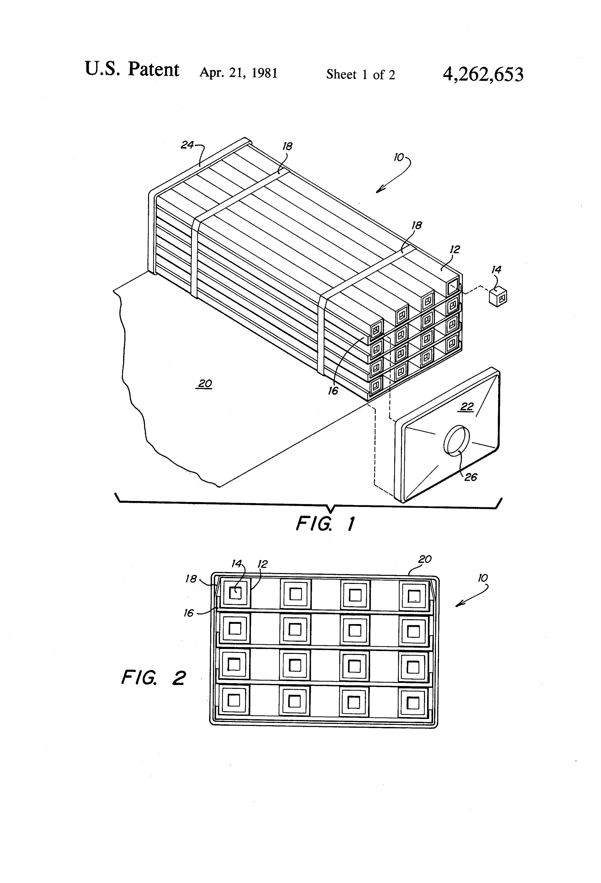
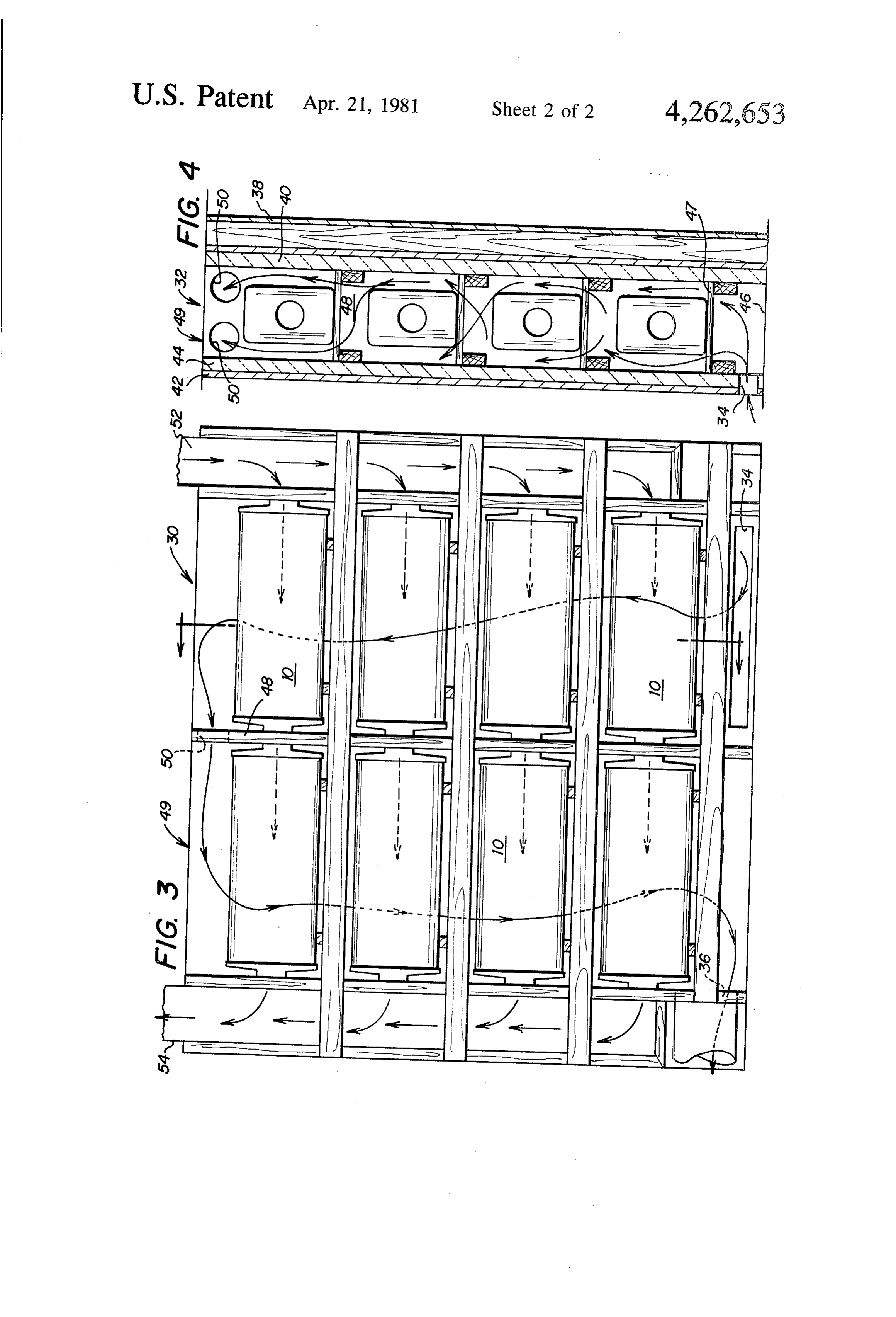
FIG. 2 is an view of the solar energy unit of FIG.
Page 2drawing sheetscan →
Page 3drawing sheetscan →
Page 4scan →
modules and returned to the interior of the building
SOLAR ENERGY HEAT STORAGE AND through the system's air conditioning ducts. Thus, the TRANSFER SYSTEM temperature of the interior of the building may be ad justed by bringing in the cooler air from the interior of
TECHNICAL FIELD 5 the building, circulating it around the exterior of the This invention relates to solar energy air conditioning heat storage modules, and returning it to the building. systems for buildings, and more particularly to a system Another advantage to the system is that the arrange for storing the heat energy from a solar collector and ment of heat storage modules may be vertically stacked transferring that stored heat energy to the interior of a O between the exterior and interior walls of a building, structure through its air conditioning system. placing them near the solar collectors, normally on the BACKGROUND OF THE INVENTION roof of the structure, without wasting the usable inte rior space of the building. The compact modular heat
The depletion and interruption of the delivery of storage devices enable a heat storage system to be used fossil fuel supplies have focused much attention on the without an air handler which makes the system ideally harnessing of solar energy as an inexhaustible source of suited for retrofitting an existing structure with a solar clean energy for the future. In many regions of the energy heating system. The solar energy heat storage country, solar energy has long been recognized as an and transfer system of the present invention is adaptable available energy source for heating a building, but such for use in other structures, such as recreational vehicles systems have met with some resistance, mostly because 20 and mobile homes where space limitations constrain full of the physical space required by such systems and their utilization of prior solar energy systems as a source of cost comparisons with existing technology. Important heat.
factors in the size and cost limitations of a solar energy A better understanding of the invention and its ad air conditioning system have been both the heat storage vantages can be seen in the following description of the component and the air handler component of the sys figures and the preferred embodiment.
tem. These factors have contributed to the problem of 25 retrofitting an existing structure with a solar energy DESCRIPTION OF THE PREFERRED system. EMBODIMENT The existing solar energy air conditioning systems FIG. 1 is a perspective view of a heat storage unit include an arrangement of heat storage components for with the end cover removed and the heat conductive receiving and storing heat energy from the solar collec exterior wrap partially removed to show the arrange tors. Heat absorbed by the collectors during the peak ment of salt tubes.
daylight hours must then be stored in the system for use at a later time to provide a continuous source of heat to 1 with the endend
FIG. 2 is an view of the solar energy unit of FIG.
cover removed.
the interior of the building. Such systems also include an air handler having associated controls to mix the cor 35 storage elements in a heatofstorage FIG. 3 is a side view one arrangement of heat and transfer system rect volume of air from the heat storage unit with the having two separate air paths for storing and transfer correct volume of air from the interior of the building. ring the solar energy.
The air handler mixes the desired percentage of air from FIG. 4 is a view of the heat storage and transfer the collector with the desired percentage of air from the system taken along the line 4-4 of FIG. 3. inside of the building and determines how much air goes back to the collectors and how much goes into the A heat storage module 10 is illustrated in FIG. 1, building. A need has thus arisen for an improved solar partially disassembled to reveal the interior of the unit. energy air conditioning system which improves the A plurality of elongated tubes 12 sealed by end covers storage of heat from the solar collectors, the transfer of 14 contain the heat of fusion material for storing the heat from the storage to the interior of the building, and 45 thermal energy collected by the solar collectors (not simplifies the flow of heated air into the building. shown). The number of tubes 12 in an array may be arranged to meet the desired heat storage capacity of
SUMMARY OF THE INVENTION the module 10. The tubes 12 and end covers 14 are In accordance with a preferred embodiment, a solar preferably constructed of a durable lightweight ABS energy heating system is provided with an arrangement 50 plastic.
of heat storage modules, such that two separate air There are a number of heat of fusion materials which paths are defined to eliminate the need for the solar air are used for storing thermal energy because of their low handler with its associated controls. The heat storage cost and high heat of fusion per unit weight. Among the modules include a plurality of closed tubes containing a acceptable phase change materials for a thermal energy heat of fusion material for heat storage, such as a salt 55 storage medium are salt-hydrates and their eutectics. hydrate mixture or phase change material. The salt One such phase change material which may be used for hydrate or phase change material tubes are situated on storing thermal heat by virtue of the heat of fusion a vertical array of support trays and enclosed within a which is released when changing from a liquid to a solid wrap of heat conductive material so as to define an air is sodium sulfate decahydrate (Na2SO4.10H2O). Such path through the heat storage module. End pieces are materials are usually placed in sealed containers to fitted over the container to connect the heat storage gether with a nucleating agent to initiate and promote module to ductwork from the solar collector as well as the formation of crystals necessary to make use of the to any desired number of additional heat storage mod heat of fusion of the material, as well as a gelling agent ules to achieve the required thermal storage capacity. A to prolong the useful life of the mixture. (The need and plurality of the heat storage modules may then be sur 65 use of such nucleating and gelling agents is discussed in rounded by a housing with suitable partitions to define U.S. Pat No. 2,677,664 and U.S. Pat. No. 3,986,969). a second path of air to flow from the interior of the The sealed tubes 12 are arranged and supported upon building around the exterior of each of the heat storage trays 16 as illustrated in FIGS. 1 and 2, such that a 5 sufficient air space is provided between adjacent tubes may be the ceiling of the structure, complete the hous 12 to provide a passageway for heated air flowing into ing 32 for defining the second flow path for air from the the heat storage module 10 from the solar collector. The interior of the building to be warmed by flowing around support trays 16 are preferably formed from a highly the heat storage modules 10. heat conductive material, such as aluminum, for the Of course, while the housing 32 has been illustrated more efficient transfer of heat from the surface of the and described as being formed between the exterior and salt-hydrate tube 12 to the exterior of the heat storage interior walls of a structure, it is to be understood that module 10. Similarly, the tubes 12 are preferably rectan the housing 32 may also be situated between the interior gular in cross-sectional area to provide maximum sur walls of a structure, or it may be a structure separate face contact with the trays 16. The support trays 16 are 10 from the walls of the air conditioned structure. vertically stacked upon one another so that the bottom In the particular arrangement of each heat storage of one support tray 16 rests upon the upper surface of module 10 illustrated in FIG. 3, the heat storage mod the eutectic salt-hydrate tubes 12 directly beneath it. ules 10 are connected in tandem pairs and are vertically This arrangement maximizes thermal contact with the stacked within the housing 32 and supported upon a salt-hydrate tubes 12 and promotes the transfer of heat 15 platform 47 to allow the cooler room air to flow around from each of the tubes 12 to the exterior of the heat the warmer heat storage modules 10. A center partition storage module 10. The heat storage module 10 shown 48 is provided between the connected pairs of heat discloses a four by four array of salt-hydrate tubes 12 storage modules 10 to force the air from inlet 34 to but, of course, the number and configuration of tubes 12 travel by convection around each of the heat storage and support trays 16 may vary to meet the necessary 20 modules 10 on one side of the transfer system 30. A design configurations of the system. parir of ports 50 are formed in the partition 48 above the A pair of straps 18 surround the vertically stacked top level of heat storage modules 10 which direct the air support trays 16 to maintain them in the desired config to flow down and around the other side of the vertical uration. Of course, for some configurations of tubes 12 stack of heat storage modules 10. The air is drawn of a module 10 it may be desirable to also include some 25 around the heat storage modules 10 on the opposite side lateral spacing device which could be integrally formed of the heat storage and transfer system 30 of FIG.3 and with the tray 16. A sheet of heat conductive material 20 through the outlet 36 by a draft created by a fan con is wrapped around the sides of the bundle of salt trolled by the air conditioning system's thermostat (not hydrate tubes 12 and vertically stacked support trays 16 shown).
to thereby define an air passageway through the heat 30 An air inlet manifold 52 provides a passageway for storage module 10 along the length of all the elongated the heated air from the solar collectors through the tubes 12. The heat conductive sheet 20 thus allows the central openings 26 that lead to each of the tandem pairs heated air from the solar collector to flow along the of heat storage modules 10. The heated collector air entire length of the salt-hydrate tubes 12 for transferring travels through the center of the heat storage modules its heat to the storage medium. The heat conductive 35 10 on one side and through the second interconnected sheet 20 also acts to conduct heat from the tubes 12 heat storage modules 10 on the other side. The collector within the heat storage module 10 to air flowing around air exits the housing 32 through an exhaust air manifold the exterior skin of the heat conductive sheet 20, as 54 and returns to the collector air system connected to shown in FIGS. 3 and 4 and discussed more fully here the solar collector.
inbelow. The heat storage module 10 illustrated in the heat Heat storage module end covers 22 and 24 are fitted storage and transfer system 30 uses sodium sulfate deca over the open ends of the heat storage module 10 to hydrate (Na2SO4.H2O) as the salt-hydrate mixture for complete the unit. The module end covers 22 and 24 thermal energy storage. The volumetric heat of fusion may be constructed of relatively inexpensive and light of such a mixture, including thickening agents and nu weight ABS plastic, and each of the end covers 22 and 45 cleating agents, as disclosed in U.S. Pat. No. 3,986,969, 24 have a central opening 26 for connecting the path of is 9,800 BTU/feet. In one particular embodiment, each air within the heat storage module 10 with the necessary tube 12 has a volume of 0.039 cubic feet, providing it ductwork connected to the solar collector system (not with the heat capacity due to the heat of fusion of the shown). euctectic salt of 382 BTU. Further, the latent heat ca FIGS. 3 and 4 illustrate an array of the heat storage 50 pacity of such a euctectic salt mixture is 0.79 BTU/(- modules 10 included in a solar energy heat storage and pounds) (F.). Given that the particular euctectic salt transfer system 30. The heat storage and transfer system tube weighs 3.55 pounds and the heat storage system 30 includes an interconnected array of heat storage operates between 90 and 100 F., the stored latent heat modules 10 to define a first path of air from the solar in each tube is 84.0 BTU, or the total heat stored per collector air system through said heat storage units 55 tube equals 466 BTU. The necessary heat storage capac returning to the solar collector air system. Further, the ity for a heat storage and transfer system 30 can be interconnected heat storage modules 10 are positioned obtained by selecting the desired number of euctectic within a housing 32 to define a second path of air flow salt tubes 12 and the desired number of heat storage for the air from the interior of the structure. The air modules 10.
from the structure flows into an inlet 34 and across the 60 In operation, in a single family residence for example, exterior surface of the heat storage modules 10, return a solar collector could be positioned on the roof of the ing to the interior of the structure through an outlet 36 structure to absorb the solar energy, with appropriate through the air conditioning ducts of the structure. ductwork transfering the heated air from the collector As illustrated in FIG. 4, the housing 32 is formed through the inlet manifold 52 to the tandemly con between an exterior wall 38 of the structure with its 65 nected pairs of heat storage modules 10, with the collec layer of insulation 40, and an interior wall 42 with its tor air exiting from the exhaust manifold 54 to complete layer of insulation 44. A bottom surface 46, which may the flow path circuit back to the solar collector. The be the floor of the structure, and a top surface 49, which energy from the sun is stored in the salt-hydrate tubes 12 6 of the heat storage module 10 during daylight hours for fusion material for storing heat from air circulated transfer to the interior of the structure through a second through said conduit;
air flow path. When the air within the interior of the a plurality of stacked trays retaining said tubes in building drops below a preferred setting, a thermostat spaced relation to allow air from the collector to may control a blower (not shown) to create a draft of 5 flow along the length of said tubes and trays, each the interior air of the home through the bottom inlet 34 tray having a thermally conductive side portion up one side of the vertically stacked heat storage mod disposed in surface engagement with one or more ules 10 and down around the remaining heat storage of said tubes to promote the transfer of heat from modules 10. The interior air is drawn by the fan through 10 said tubes to siad trays and to said conduit; and, the outlet 36 to the rest of the home's air conditioning end coverings fitted over the open ends of said con ductwork. duit, said end covers having inlet and outlet open ings, respectively, for admitting and discharging
While a particular embodiment of this invention has air circulated from the solar collector through said been shown and described above, it is obvious that conduit along the length of said tubes. changes and modifications can be made without depart 15 2. The solar energy module of claim 1, wherein said ing from the true spirit and scope of the invention. It is tubes and said conduit have a rectangular cross-sec the intention of the appended claims to cover all such tional area.
changes and modifications. 3. The solar energy module of claim 1, wherein sup I claim: porting straps surround said arrangement of stacked 1. A solar energy storage module for use in a solar 20 trays, retaining said tubes and said trays in alignment. energy heat storage and transfer system for storing 4. The solar energy storage module of claim 1, thermal energy gathered by a solar collector and trans wherein said heat of fusion material is a salt-hydrate. 5. The solar energy storage module of claim 4, ferring the stored thermal energy to an air distribution wherein system comprising: said salt hydrate is a eutectic mixture. 25 6. The solar energy module of claim 1, wherein said a sheet of thermally conductive material forming as sheet of thermally open-ended, elongated conduit for connection in aluminum. conductive material is a sheet of fluid communication with the solar collector; 7. The solar energy storage module of claim 1, a plurality of elongated heat storage elements re wherein said sealed tubes and said end covers are ceived within said conduit, each heat storage ele- 30 formed from a plastic material.
ment including a sealed tube containing heat of it is sk k :
Provenance
- Collection
- Patents citing this work
- Pages
- 6
- Method
- pdftotext (the PDF's own text layer) + pdftoppm 300dpi page scans
- Patent office record
- patents.google.com →
- Source
- Google Patents citing-documents table
- Assignee
- Neha International
- Published
- 1981-04-21
- Transcribed from
- patentimages.storage.googleapis.com →