

patent · US4265223A
Method and apparatus for utilizing solar energy
5 May 1981
Text
Page 1bibliographic recordscan →
United States Patent (19)
Miserlis et al.
(54) METHOD AND APPARATUS FOR
UTILIZING SOLAR ENERGY
75 Inventors: Constantine D. Miserlis, Arlington;
Albert G. Luke, Jr., Stoneham, both of Mass.; Walter Laber, Deggendorf
Friedrich Guetlhuber, Metten, both of Fed. Rep. of Germany Assignees: The Badger Company, Inc.,
Cambridge, Mass.; Deffendorfer
Werft und Eisenbau, Deggendorf,
Fed. Rep. of Germany
(51) Int. Cl.................................................. F24J 3/02 (52) U.S. Cl. .................................... 126/435; 126/452;
1,951,403 3/1934 Goddard .............................. 126/435 3,903,699 9/1975 Davis........... 126/435 X 3,950,949 4/1976 Martin et al..... ... 60/676 X
HIGH
EXTRA
HIGH
TEMP
COLLECTOR
4,063,546 12/1977 Schmid et al. ................... 126/437 X 4,065,053 12/1977 Fletcher et al. ....................... 60/641 4,117,682 10/1978 Smith ..................................... 60/659 4,143,814 3/1979 Hill, Jr. ............................ 126/437 X 4,146,057 3/1979 Friedman et al ... 126/435 X 4,164,123 8/1979 Smith ..................................... 60/641 4, 172,491 10/1979 Rice ................................. 126/435 X Primary Examiner-James C. Yeung
Assistant Examiner-Larry Jones
Attorney, Agent, or Firm-Schiller & Pandiscio
A process and system are provided for economic utili zation of solar energy. Solar energy is absorbed and converted to thermal energy by means of at least two systems, operating in different temperature ranges, for circulating a primary fluid heat transfer medium through separate collector sections of a solar receiver to recover solar heat and through separate output heat exchangers to supply heat to a second heat transfer medium functioning as a working medium, with heat storage means being associated with each system for the purpose of satisfying the heat requirements of the work ing fluid and also to prevent cooling down of the collec tor during the time that little or no solar radiation is available.
25 Claims, 7 Drawing Figures
HIGH
EXTRA
TEMP.
STORAGE
Drawings
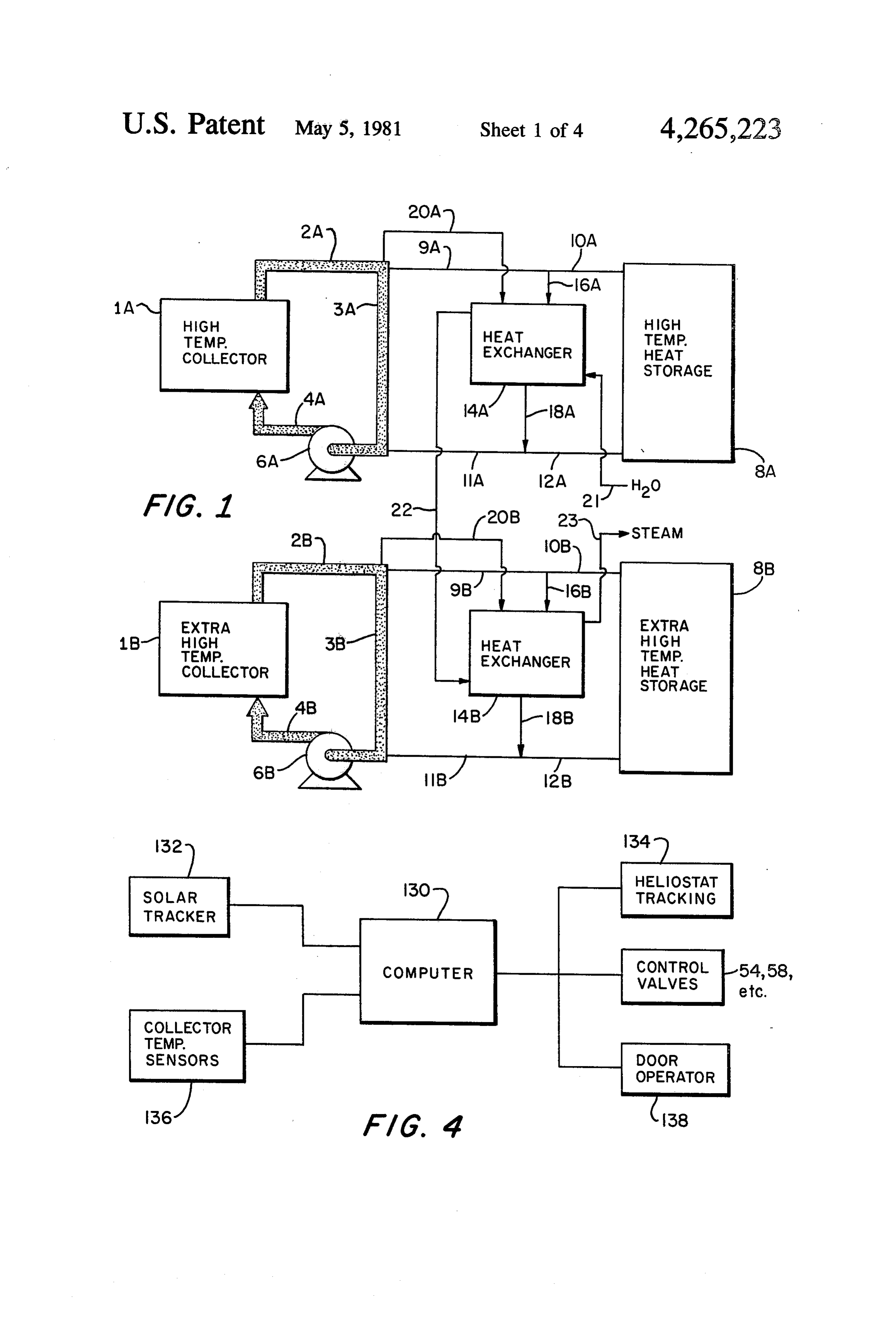
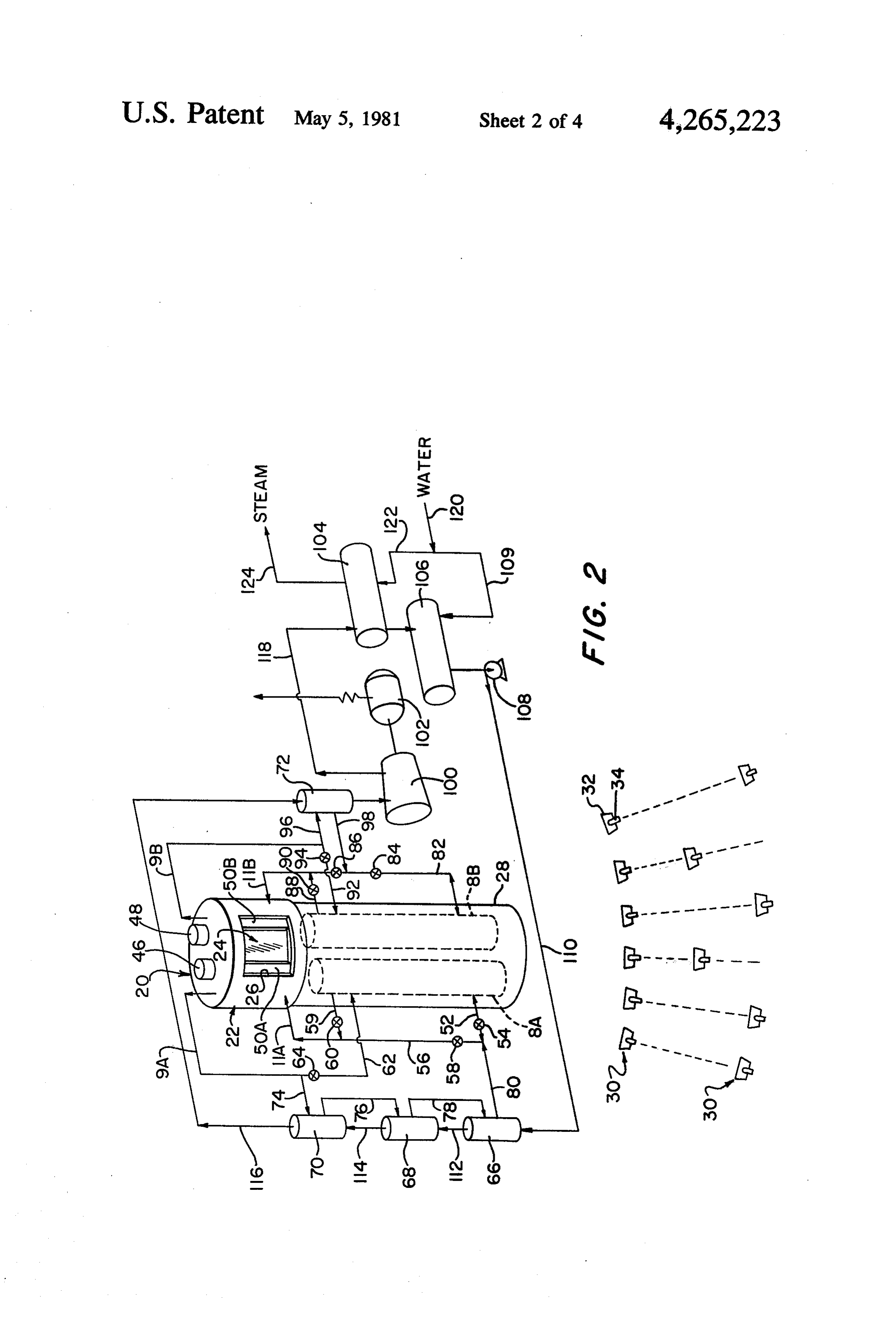
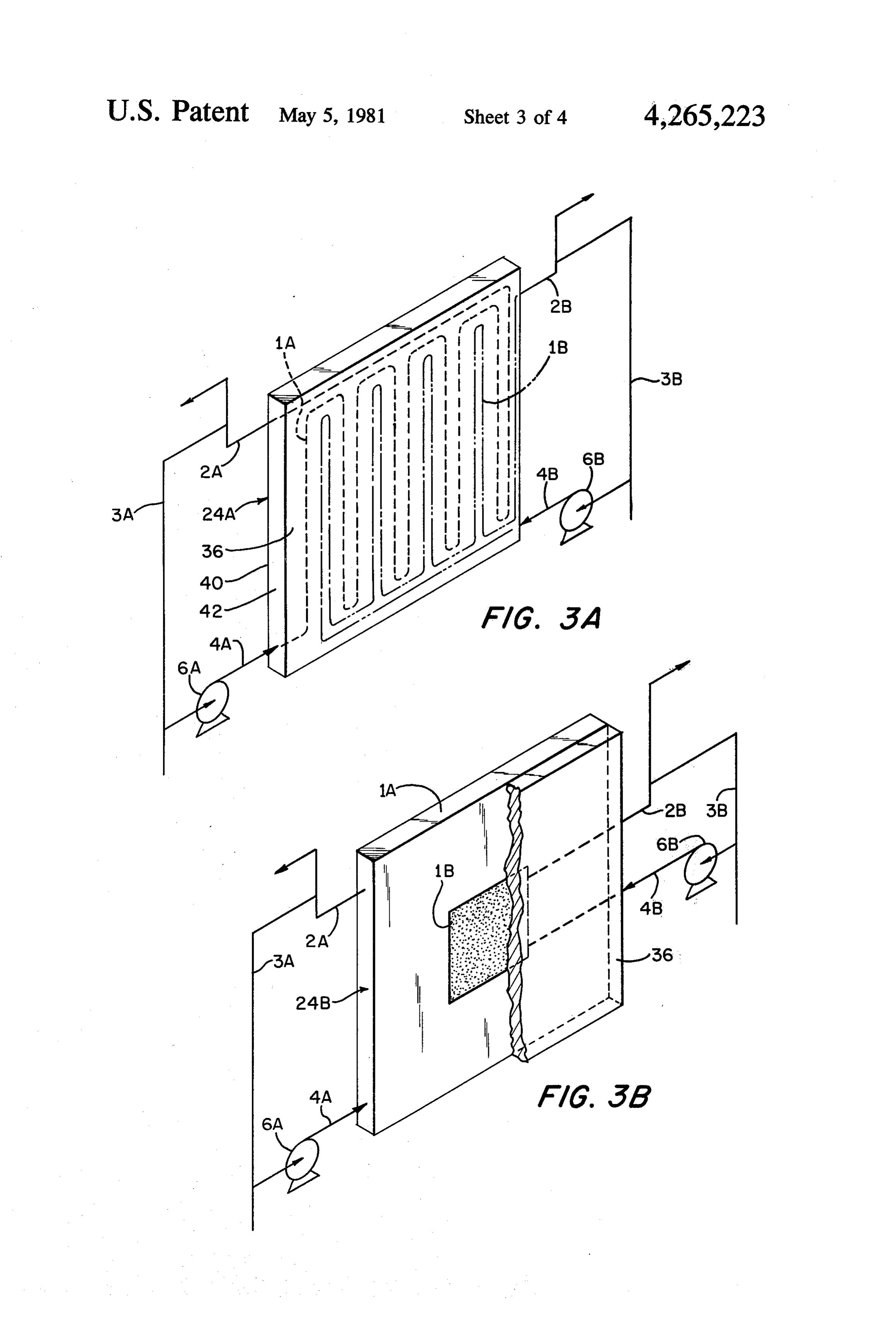
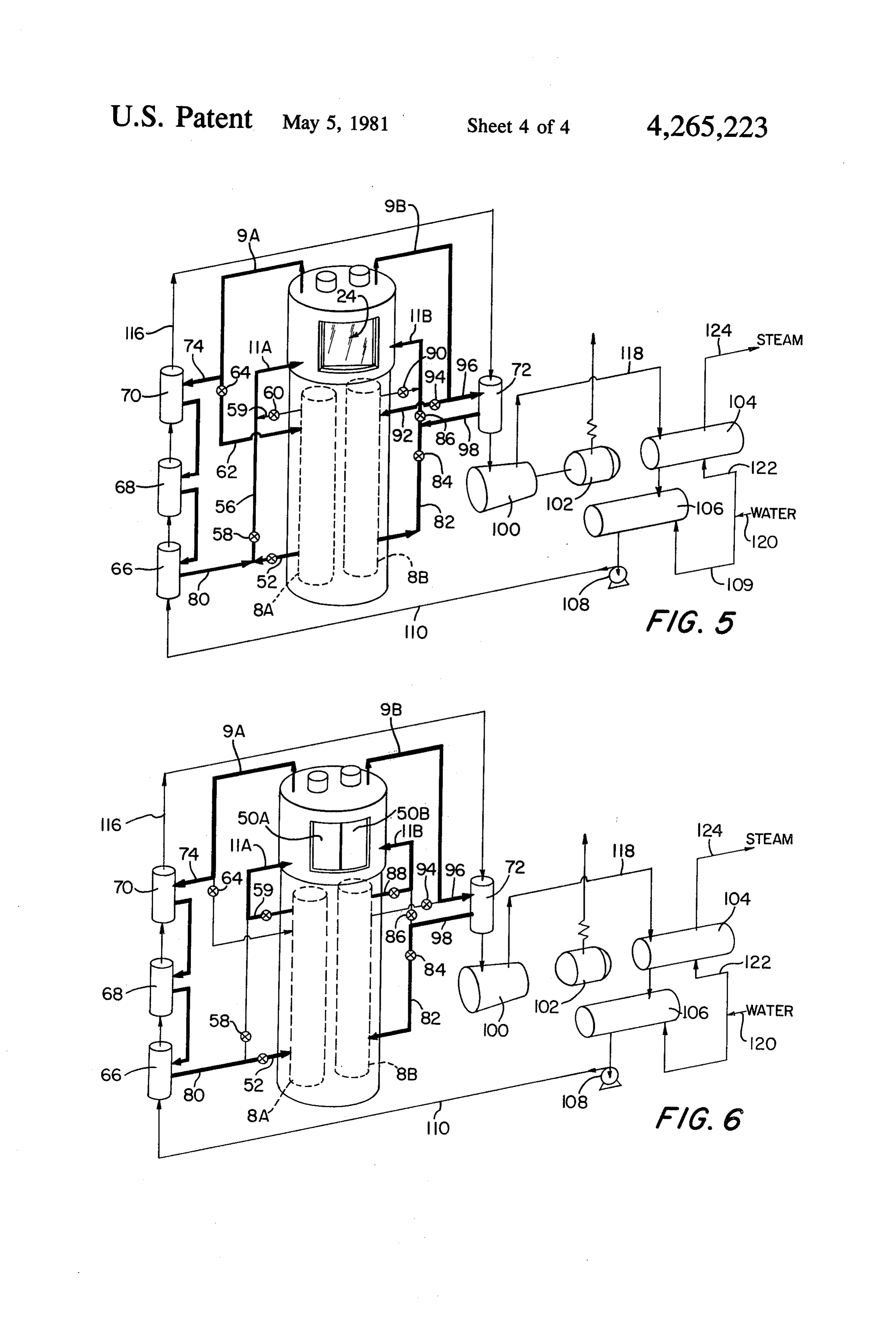
FIG. 1 is a schematic diagram of the invention; auxiliary piping and control instrumentation for carry FIG. 2 is a perspective and diagrammatic view of a ing out the process embodied in the invention, as herein solar energy collection and utilization system which 50 after described.
Page 2drawing sheetscan →
Page 3drawing sheetscan →
Page 4drawing sheetscan →
Page 5drawing sheetscan →
Page 6scan →
above the usual range of superheated steam. Hence
METHOD AND APPARATUS FOR UTILIZNG should the incident solar radiation be interrupted, the SOLAR ENERGY receiver or at least portions thereof will be cooled from the highest steam temperature in the system down to the
This invention relates to solar energy conversion lowest boilder feedwater temperature. As a result of this systems and more particularly to systems for collecting drop, stresses and even shocks are produced in the ma solar energy and converting it to other forms of usable terials of construction of the receiver. Similar stresses energy through the use of a fluid heat transfer medium. are produced as a result of the large temperature in BACKGROUND OF THE INVENTION crease which occurs when the receiver is again illumi 10 nated with solar radiation.
It has long been recognized that the sun is a vast This problem of thermally-induced stresses exists source of clean energy and that it can and should be even if the recovered solar energy is used to generate exploited to reduce dependence on fossil fuels. How steam through an intermediate heat transfer medium ever, systems heretofore available for collecting and which permits at least temporary storage of the recov utilizing solar energy have not been sufficiently eco 15 ered heat and is capable of being heated high enough to nomical to complete effectively with fossil fuels. permit production of 900-1200' F. steam. In this con One approach that has been taken to enhance cost-ef. nection it should be noted that using a working fluid fectiveness involves providing (1) a receiver located on other than steam to operate a turbo-generator is not a tower or on a hill and (2) a mirror field comprising a favored since most are designed to be operated by plurality of adjustable mirrors situated on the ground 20 Steann.
and arranged to reflect the sun's rays towards the re These thermally-induced stresses, which occur re ceiver. The receiver consists of one or more collectors and energy conversion means for collecting the incident and may adversely peatedly, affect the life span of the receiver even affect the performance of associated radiant energy and converting it to heat. The mirrors, equipment. Since the capital cost of a solar plant of the also known as heliostats, are continually repositioned by 25 a servo-tracking system during each day as well as type described is very high, its useful life must be quite seasonally so as to compensate for relative movement long, typically at least twenty years, in order for the between the sun and earth and thereby contantly direct plant to be economically feasible. However, in solar the reflected solar energy at the receiver. The tracking plants of prior design the stresses created by sharp system may be adapted to compensate for movement of 30 changes in the amount of incident solar radiation are of the receiver due to various factors, notably wind load sufficient magnitude and frequency as to drastically ing. The heat energy produced as a consequence of foreshorten the useful life of the receiver or necessitate absorption of incident solar radiation by the receiver is frequent and expensive shutdowns for repair. Other recovered by absorbing it in fluid heat transfer medium problems with prior systems employing a centralized and passing the latter to or through a heat storage vault 35 energy receiver mounted above and some distance from or through a consuming device which may take various the heliostats is that dispersion of the reflected beams, forms such as a hot water heater or steam producer or due to pointing or other factors, tends to dilute the solar turbo-electric generator. It has been suggested that the flux so that some of it may not reach the target area of recovered heat may be stored by absorbing it in a heat the receiver and/or so that a precise uniformity of flux storage media of fluid or solid form, e.g. eutectic salts or 40 distribution over the target area of the receiver is not a bed of stones. Examples of systems embodying cen obtainable. While making the target area of the receiver tralized energy receivers, mirror fields, servo-con larger will help in intercepting more of the solar energy trolled sun-tracking heliostats, heat storage tanks, and reflected by the heliostats, it also involves larger re use of fluid heat transfer media for utilizing absorbed ceiver construction and maintenance costs. Moreover, solar energy are disclosed by U.S. Pat. Nos. 4,063,543, 45 since making the target area larger does not provide 4,044,753, 4,034,735, 4,031,444, 4,021,895, 4,091,495 and greater uniformity of flux distribution, an increase in 4,013,885. temperature differentials across the receiver (sometimes The prior art solar energy collection and utilization with an attendant reduction in overall conversion effi systems do not adequately accommodate and compen ciency) is a likely result of increasing the size of the sate for the fact that the amount of energy from the sun 50 target area. Hence, the problem of stresses is not arising at the earth's surface is not constant but will vary avoided by making the receiver larger and in fact it is with the amount of cloud cover and the time of day. desirable to avoid building larger receivers so as to Also the time between sunrise and sundown will vary reduce weight and improve the resistance to wind load from day to day. Accordingly if the recovered solar ing, whereby to achieve a relatively good structural energy is utilized immediately to generate steam from 55 strength-to-cost ratio.
water, a number of disadvantages are incurred. If the OBJECTS AND SUMMARY OF THE steam is used to drive an electrical power generator, the INVENTION latter must be continually started up and shut down in accordance with the amount of available steam since In view of the state of the prior art, a general and the latter cannot be stored. This is most uneconomical primary purpose of this invention is to provide an im since the efficiency of a turbine installation is very low proved method and system for collecting and utilizing when operating under reduced or intermittent loads solar energy which is reliable and capable of operating which lie outside of its design parameters. Furthermore, satisfactorily over the long life expected of utilities in such a system the receiver will experience tempera facilities.
tures ranging from that of the boiler feedwater up to the 65 A further object is to provide a method and system temperatures to which steam is required to be heated for for the purpose described which has enhanced energy efficient turbine-driving purposes (usually between conversion and utilization capabilities, low operating about 900-1200' F.), and often it has temperatures even costs and no fuel requirements, and is capable of driving 7 the turbine section of a turbo-electrical generator within those portions of the electromagnetic wave energy its design limits. spectrum, within or outside of the visible range, which Still another object is to provide an energy collection emanate from the sun and which may be converted by and utilization method and system for effectively com absorption to thermal energy.
peting with systems employed in collecting and utiliz FIG. 1 is a schematic representation of the invention. ing energy extracted from fossil fuels. Essentially it involves the provision in a receiver of two Another object is to provide a novel system and collectors (or a single collector having two discrete method for converting radiant solar energy to thermal sections) as represented at 1A and 1B, with each collec energy which involves substantially preventing the tor essentially comprising a heat exchanger through receiver from undergoing larger and frequent excur O which a primary fluid heat exchanger medium may be sions of temperature, whereby to reduce stresses and circulated to recover or give up heat as hereinafter shock due to changes in temperature and extend the described. Each collector is connected into a separate useful life of the receiver. fluid heat transfer medium circulating system, with the A further object is to provide a method and system system associated with collector 1B being operated whereby heat recovery is effected by a fluid heat trans 15 within a higher temperature range than the system asso fer medium which is used in a mode which facilitates ciated with collector 1A. Each circulating system has a profitable operation of a power plant. recycle loop comprised of lines 2A, 3A and 4A or 2B, These and other objects and advantages are achieved 3B and 4B between the inlet and outlet of the heat ex by using a primary fluid heat transfer medium which is changers of the associated collector and a pump as contained in at least two separate circulating systems shown at 6A and 6B for circulating the medium through having different operating temperature ranges, and a each system. Additionally each circulating system com secondary fluid heat transfer medium which functions prises a heat storage unit 8A or 8B connected by lines as a working medium and, by exchange of heat with the 9A, 10A or 9B, 10B and 11A, 12A or 11B, 12B to the primary heat transfer medium in the separate circulat outlet and inlet sides respectively of the associated col ing systems, is brought stepwise up to a relatively high 25 lector heat exchanger 1A or 1B and loops 2A, 3A, 4A temperature suitable for subsequent purposes, e.g., driv or 2B, 3B, 4.B. Each circulating system also includes a ing the turbine section of a turbo-generator so as to secondary heat transfer medium heat exchanger 14A or produce electricity. The conditions necessary for effi B having its heat input section connected by lines 16A cient turbine operation and avoidance of large tempera or 16B and 18A or 18B to the lines 9A, 10A or 9B, 10B ture fluctuations in the receiver are achieved by asso 30 and 11A, 12A or 11B, 12B as shown. Additional lines ciating heat reservoirs with each circulating system so 20A and 20B connect the lines 2A and 2B to the heat that the primary heat transfer medium in each circulat input sections of heat exchangers 14A and 14B respec ing system may be circulated in a mode which transfers tively. A secondary or working fluid heat transfer me heat (a) to the reservoir in times of high solar energy dium is circulated via lines 21, 22 and 23 through the flux, (b) to the receiver in times of scant solar energy 35 heat output sections of heat exchangers 14A and B so as flux, (c) to the secondary fluid from the receiver in to recover heat from the primary heat transfer medium. times of high solar energy flux, and (d) to the secondary The same or a different material may be used in the fluid from the reservoir in times of scant solar energy two circulation systems as the primary heat transfer flux. In addition a curtain or door may be provided for medium; however, the latter is a material which is a closing off the target area of the receiver during times 40 liquid at the temperatures at which it is transported of scant or no incident solar energy flux so as to reduce through its circulation system. Preferably it is a molten heat loss from the receiver to the environment. Other salt or a eutectic salt mixture with characteristics suited features and aspects of the invention are revealed or to the temperature range encountered in its movement made obvious by the following detailed description and between the collector 1A or 1B, storage unit 8A or 8B claims in light of the accompanying drawings. 45 and the secondary heat transfer medium heat exchanger BRIEF DESCRIPTION OF THE DRAWINGS 14A or 14B. Although not shown in FIG. 1, the system also includes other structural elements such as valves,
FIG. 1 is a schematic diagram of the invention; auxiliary piping and control instrumentation for carry FIG. 2 is a perspective and diagrammatic view of a ing out the process embodied in the invention, as herein solar energy collection and utilization system which 50 after described.
embodies the principles of the present invention and A basic requirement of the process is that the two includes a central receiver disposed above a field of circulating systems be operated at near but different individual heliostats and provided with doors for its temperature ranges and the working secondary heat target area; transfer medium be heated stepwise by heat exchangers FIGS. 3A and 3B are enlarged schematic views of 55 14A and 14B. Additionally the primary heat transfer two forms of solar collectors useable in the receiver of medium in each system is circulated continuously the system of FIG. 2; through the loop 2A, 3A, 4A or 2B, 3B, 4B, as the case FIG. 4 is a diagram illustrating the controls required may be, in sufficient quantity to maintain a relatively for operating the system of FIG. 2 according to the small difference between its temperature at the return method of this invention; and 60 and discharge sides of the collector. Finally, the pri FIGS. 5 and 6 are like FIG. 2 but illustrate different mary heat transfer medium in each circulating system is operating modes of the system. circulated so as to transfer heat from the collector to the In the drawings, like numerals refer to like parts. storage unit when the amount of heat recovered from DETAILED DESCRIPTION OF THE received solar energy exceeds the heat input require 65 ments of the working fluid, and also so as to transfer
Invention
heat from storage to the collector when solar radiation
As employed herein, the terms "solar energy', "radi is reduced or absent in an amount sufficient to hold the ant energy' and "solar flux' are intended to denote collector temperature relatively constant.
Page 8scan →
For a solar power plant where the secondary work temperature of the medium in lines 4A and 4B at the ing fluid is steam which is used to drive the turbo-gener inlet of the collector, the medium in lines 2A and 2B ator, it is preferred that the primary fluid heat transfer may be used to supply heat to the working fluid. There medium in the circulating system associated with col fore during this mode of operation heat transfer medium lector 1A be circulated so that it have temperatures of 5 is continually transported by lines 20A and 20B to heat about 950 F. and about 1000' F. at the collector's inlet exchangers 14A and 14B respectively where it is cooled and outlet respectively, and the heat transfer medium in by indirect heat exchange with the working fluid. This the second circulating system be maintained with tem cooled stream of heat transfer fluid is passed from heat peratures at the inlet and outlet of collector 1B of about exchangers 14A and 14B to heat storage reservoirs 8A 1150 F. and about 1200' F. respectively. Of course, 10 and 8B via lines 18A, 12A and 18B, 12B respectively. depending upon the heat requirements of the secondary The advantages of a system as represented in FIG. 1 fluid, other temperature limits may be maintained in the are as follows: (1) during times of peak solar energy, two circulating systems, e.g. between about 800 and excess heat can be recovered by removing a relatively 900 F. in the system for collector 1A and between cool stream of primary heat transfer medium from its about 950 and 1050 F. in the second circulating sys 15 storage area and passing it through the associated col ten. lector to pick up heat and then back to the storage area In all modes of operation the process requires that the for later retrieval and use as required; (2) the near con primary fluid heat transfer medium in each circulation stant temperature differential maintained between each system be continuously circulated in the system's recy collector's inlet and outlet reduces thermal stresses due cle loop 2A, 3A, 4A or 2B, 3B, 4.B. In normal daytime 20 to avoidance of large temperature gradients across the operation, some of the heat transfer medium in each expanse of the collector; (3) keeping the collectors at a circuit is passed by lines 9A, 16A or 9B, 16B to heat substantially constant level avoids the large thermal exchanger 14A and 14B, and a corresponding amount of stresses that otherwise would be produced by large the same medium is returned to line 4A or 4B via lines changes in the intensity of solar radiation; (4) by utiliz 18A, 11A, or 18B, 11B, whereby the hot medium in line 25 ing two circulation system with different temperature 3A is mixed with that in line 11A and the hot medium in ranges it is possible to extract relatively large amounts line 3B is mixed with that in line 11B, with desired inlet of heat for increased power generation without subject and outlet temperatures at the collector inlet and outlet ing the collectors and the primary heat transfer medium being achieved by appropriately proportioning the flow to large temperature excursions; and (5) by using differ rates in loops 2A, 3A, 4A, and 2B, 3B, 4B with the flow 30 ent temperatures and different materials as the primary rates in the secondary loops 9A, 16A, 18A, 11A and 9B, heat transfer medium in each circuit, it is possible to (a) 16B, 18B and 11B respectively. The system is sized so select a heat transfer medium that is especially suited for that in normal daytime operation more heat is generated a particular operating temperature range, and (b) to use in the collector than is required to be consumed by the a relatively inexpensive fluid heat exchange medium secondary working fluid in exchangers 14A and 14.B. 35 and relatively low cost structural metal members in the This excess heat is stored by passing some of the hot lower temperature circuit and a more expensive heat fluid heat transfer medium in lines 2A, 9A and 2B, 9B transfer medium and structural members as required in through lines 10A and 10B to the heat reservoirs 8A and the higher temperature circuit. In this connection it is to 8B respectively, and a corresponding amount of rela be noted that usually the higher the operating tempera tively cold heat transfer medium is removed from the 40 ture of a fluid handling system, the more expensive will heat storage units and returned via lines 12A, 11A and be its construction and the more critical will be the 12B, 11B to lines 4A and 4B respectively. nature and handling of the materials employed. Hence, In the event of temporary cloud cover whereby the another significant advantage is that the higher temper recovered solar thermal energy is insufficient to satisfy ature circulation system may be made much smaller in the heat requirements of the secondary working fluid, 45 size, especially if its output heat exchanger is employed the heat deficiency is made up by feeding relatively hot merely as a final stage steam superheater. fluid heat transfer medium from the storage units 8A FIG. 2 illustrates a solar energy collection and utiliz and 8B to the exchangers 14A and 14B via lines 10A, ing system which constitutes a preferred embodiment of 16A and 10B, 16B respectively. Corresponding amounts the invention. This embodiment comprises a receiver 20 of primary heat transfer medium are returned to the 50 comprising a housing 22 which contains a collector storage units via lines 18A, 12A and 18B, 12B respec panel 24 for absorbing solar energy via an aperture 26, tively. During this time, flow continues as during nor a support 28 supporting the receiver above the surface mal daytime operation in the loops 2A, 3A, 4A, and 9A, of the earth, and a mirror field made up of a plurality of 16A, 18A, 11A of one circulating system and in the undivided heliostats 30. Although not shown in detail, it corresponding loops 2B, 3B, 4B, and 9B, 16B, 18B, 11B 55 is to be understood that each heliostat includes a reflect of the other system. ing surface 32 and servo-positioning means 34 for dy In the event of darkness or when cloud cover is suffi namically moving the reflecting surface so as to main ciently dense and permanent that practially no energy is tain the reflected rays from the sun directed toward the collected from the sun, substantially all of the heat re target area presented by the collector panel 24 of the quired by heat exchangers 14A and 14B is provided by 60 receiver when sun light is available. The servo position heat reservoirs 8A and 8B respectively. During this ing means necessarily must be operated to continuously mode of operation, hot heat transfer medium is trans compensate for the relative movement between the sun ferred from the heat storage units to the collectors via and earth during daylight hours and seasons. The servo lines 10A, 9A, 3A, 4A and 10B, 9B, 3B, 4B, and a corre positioning means for each heliostat may have its own sponding amount of the same medium is removed from 65 sun sensor(s) for detecting relative movement of the sun the loops 2A, 3A, 4A and 2B, 3B, 4B respectively. Since and earth and determining the direction and extent of the temperature of the medium in lines 2A and 2B at the reflector movement required to maintain the reflected outlet of the collectors is only minimally below the solar energy directed at the target area of the receiver, 9 e.g. like the heliostats disclosed in U.S. Pat. No. Although not shown, it is to be understood that the 4,063,543. Alternatively a single central sun tracker and heat exchangers in the receiver may be disposed other a computer may be used to sense relative movement than as shown in FIGS. 3A and B, e.g., each of the two between the sun and earth and to provide positioning heat exchangers may remove heat from one half of the signals for individually controlling operation of the target surface, with each such half extending from top servo-positioning means of the several heliostats. Since to bottom or side to side. Preferably, however, the the design, function and control of heliostats are well exchangers are disposed so that each removes heat from known, a further detailed description of the heliostats is the same area of the target surface, as in the design of omitted in the interest of brevity. However, it is to be FIG. 3A. It is to be understood also that each of the heat understood that various forms of heliostats, e.g. those 10 exchangers 1A and 1B may be made up of two or more with flat or curved reflectors, may be employed in the heat exchanger sections connected in series or in paral practice of this invention. lel with each other.
The collector panel may take various forms, but at The pumps 6A and 6B and the lines 2A, 3A, 4A and the very least it comprises a target surface for absorbing 15 2B, 3B, 4B making up the two recycle loops are con solar energy as heat and at least two heat exchangers in tained within the receiver, with the pumps 6A and 6B heat-exchanging relation with said energy-absorbing preferably being driven by separate electric motors 46 means, with each heat exchanger forming part of a and 48 respectively mounted to the receiver. separate circuit for circulating a primary heat transfer In the usual installation it is preferred that the re medium. ceiver housing be insulated to reduce radiative heat In the preferred embodiment of the invention shown 20 losses and that the aperture 26 be closed off during in FIGS. 2, 4, 5 and 6, the collector panel comprises two periods of darkness or when the sun is occluded by heat exchangers. However, it is to be understood that clouds for a substantially time. Accordingly, a pair of the receiver may have additional heat exchangers with side-wise moving doors 50A and 50B are mounted in each one forming part of a separate circuit for a primary 25 the receiver. FIG. 2 shows the doors partially closed, heat transfer medium. FIGS. 3A and 3B illustrate two while the doors are fully open in FIG. 5 and fully closed different forms of collectors 24 that may be employed in in FIG. 6. Although not shown in FIG. 2, it is to be understood that an electrically powered door operator a receiver according to this invention.
As seen in FIG. 3A, the collector panel 24A com unit isormounted in the receiver for moving the doors to prises a front surface 36 which (a) serves as the target at 30 open closed position on command. Referring now to FIG. 2, the receiver support 28 is which the beam of radiant energy from each heliostat is preferably directed and (b) preferably is made so that it has a high within it areaseparateclosed hollow structure and disposed heat storage units 8A and 8B, one radiant energy absorption efficiency, low emissivity and for each heat exchanger in the receiver. Specific details high thermal conductivity. Thus, target surface 36 may of construction of the heat storage units are omitted be a sheet of aluminum with a dark, light-absorbing 35 since such devices are well known in the art and the coating on its front side. In the preferred embodiment form of construction may vary according to the needs shown in FIG. 3A, collector panel 24A also comprises of different installations. Suffice it to state that each heat two heat exchangers 1A and 1B in heat-exchanging storage unit is capable of storing relatively large quanti relation with target surface 36. In this case the heat ties of a fluid heat transfer medium and is insulated exchangers comprise conduits which are arranged so as 40 against loss of heat. By way of example but not limita to form serpentine coils of generally similar shape dis posed adjacent to and co-planar with one another, tion, age each storage unit may comprise an insulated stor tank made of a material which is inert to the fluid whereby a fluid heat transfer medium circulating heat transfer medium.
through the coil of one heat exchanger will exchange The bottom end of storage unit 8A is connected by heat with substantially the same area of the target sur 45 lines 52 and 56 and valves 54 and 58 to return line 11A face as will occur when a fluid heat transfer medium is of exchanger 1A of collector 24. The upper end of circulated through the coil of the other heat exchanger. storage unit 8A is connected by a line 59 and a valve 60 The conduits may take the form of pipes mounted be to line 11A. Still another line 62 and a valve 64 connect hind and in heat-exchanging relation with the target discharge line 9A to the upper end of storage unit 8A. surface. The pipes may be exposed on the rear side of 50 Also associated with heat exchanger 1A are three work the collector or the solar panel may include a back wall ing fluid heat exchangers 66, 68 and 70, with exchanger 40 and side walls 42 embodying the pipes. Alternatively 66 functioning as a feedwater preheater, exchanger 68 the conduits may be passageways demarcated by the functioning as a primary steam generator, and ex partitions extending between the front and back wall 36 changer 70 functioning as a first steam superheater. A and 40. The inlets and outlets of collectors 1A and 1B 55 fourth working fluid heat exchanger 72, which func are connected to lines 4A, 4B and 2A, 2B respectively tions as a second steam superheater, is associated with as shown. heat exchanger 1B of collector 24. Exchangers 66, 68, FIG. 3B shows another form of collector that may be 70 and 72 may be of any suitable design, e.g., shell and used in the system of FIG. 2. In this case the collector tube units. In any event it is to be appreciated that each 24A has two heat exchangers represented schematically 60 has heat input section and a heat output section. The as 1A and 1B which are disposed so that exchanger 1B return side of the heat input section of exchanger 70 is collects heat from a selected center area of the target connected by a line 74 to lines 62 and 9A, while its surface 36 and exchanger 1A collects heat from the area discharge side is connected in series with the return side of the target surrounding the center area. The target of the heat input section of exchanger 68 by a line 76. surface 36 may be an integral and essential part of the 65 Another line 78 connects the discharge and return sides heat exchangers or, as shown in FIG. 3B, it may be a of the heat input sections of exchangers 68 and 66. The separate sheet or panel attached to and in conductive discharge side of the heat input section of exchanger 66 heat transfer with the two exchangers. is connected by a line 80 to lines 52 and 56.
Page 10scan →
The bottom end of storage unit 8B is connected by a during nightime and prolonged periods of radiating line 82 and valves 84 and 86 to the return line 11B of occluding cloud cover.
heat exchanger 1B. The upper end of the same storage FIG. 5 illustrates operation of the system of FIG. 2 unit is connected by a line 88 and a valve 90 to line 11B. during a period of sunlight sufficiently intense for ex Still another line 92 and a valve 94 connect the dis 5 cess heat to be available for storage in heat reservoirs charge line 9B of collector exchanger 1B to the upper 8A and 8B. During such period, the doors 50A and 50B end of storage unit 8B. Line 9B also is connected by a are open full so as to expose the full target area of col line 96 to the return side of the heat input section of lector 24. Valves 60 and 90 are closed and the rest are working fluid heat exchanger 72, while the discharge opened, whereby the primary fluid heat transfer me side of the same heat input section is connected by a line 10 dium is forced by the pumps 6A and 6B to follow the 98 to lines 82 and 11B. paths represented by the bold lines. Thus relatively cold Still referring to FIG. 2, the preferred embodiment of heat transfer medium is removed from the bottom of the invention comprises a turbine 100 connected in storage units 8A and 8B and fed via lines 56, 11A and driving relation with an electrical power generator 102, 82, 11B to the input ends of the heat exchangers 1A and a heat exchanger 104 which functions as an export 15 1B of collector 24. Hot heat exchange medium is re steam generator, a collection drum 106, and a pump 108. moved from the recycle loop 2A, 3A, 4A of exchanger Makeup boiler feedwater is supplied by a line 109 to 1A by line 9A and some of it flows via line 74 to heat collection drum 106 as required. Water collecting in exchangers 70, 68 and 66 in turn, while the remainder is drum 106 is passed by pump 108 and lines 110, 112, 114, passed by line 62 back into the upper end of storage unit 116 through the heat output sections of heat exchangers 8A. The fluid heat transfer medium discharged from 66, 68, 70 and 72 in the order named, with water being exchanger 66 is returned to the collector via lines 80, 56 preheated to nearly its boiling point in exchanger 66 and and 11A. At the same time hot heat storage medium is substantially all of the water being converted to steam removed from the recycle loop 2B, 3B, 4B of collector in generator 68. This steam is superheated in exchangers exchanger 1B by line 9B and some of it is fed by line 96 70 and 72 and then it is passed through turbine 100 so as 25 to heat exchanger 72, while the remainder is passed by to cause the latter to operate generator 102. As the line 92 back into the upper end of storage unit 8B. The steam is discharged from the turbine it passes via a line relatively cold medium from exchanger 72 is returned 118 and the return side of the heat input section of ex to the collector via lines 98 and 11B. If desired, particu changer 104 back to collection drum 106. Boiler feed larly where the volume or capacity of storage unit 8B is water is circulated via lines 120 and 122 through the 30 relatively large so that more than enough heat is stored heat output section of exchanger 104, whereby the therein during an average day of abundant daylight to boiler feedwater is converted to steam as a consequence take care of the heat required for reverse nightime oper of recovery of heat from the spent superheated steam ation, the foregoing operation may be modified to the passing out of the turbine. The steam produced in ex extent of closing valves 84 and 94, whereby all of the changer 104 is exported for use in another existing facil 35 heat recovered in collector heat exchanger 1B is utilized ity, e.g., a petrochemical processing plant or a water in heat exchanger 72.
desalination unit. FIG. 6 illustrates operation of the same system com As noted above, the same or different materials may mencing at sunset. For this mode of operation, valves be used as the primary fluid heat transfer medium circu 58, 64, 86 and 94 are closed and the remainder are open. lated through the two collector heat exchangers 1A and Additionally, if doors 50A and 50B or equivalent are 1B and the primary heat transfer medium is preferably a provided, they should be moved to a closed position as molten salt or a salt mixture which remains in the liquid shown in F.G. 6 so as to reduce loss of heat by the phase throughout the range of high temperatures en collectors by radiation to the surrounding environment. countered in the circulation system. One salt mixture During night time, hot primary heat transfer medium that may be used is eutectic sodium nitrate/sodium 45 accumulated during the day in storage units 8A and 8B nitrate. Still other high temperature salts are known to is removed from those storage units via lines 59, 11A persons skilled in the art. Molten metals also may be and 88, 11B and pumped through the collector heat employed as the primary heat transfer medium; a suit exchangers in the receiver for the purpose of maintain able oil could be used as the primary heat transfer me ing the temperature of the collector at substantially the dium where the operating temperature so permits. 50 same level as it was during day time operation. The heat Referring now to FIG. 4, operation of the system of transfer medium is removed by lines 9A and 9B from FIG. 2 may be automated by means of a computer 130 the loops 2A, 3A, 4A and 2B, 3B 4B respectively and is which may be preprogrammed to automatically adjust passed via lines 74 and 96 to the heat exchangers 70 and the position of the heliostats in accordance with signals 72. After indirect heat exchanger with the secondary received from a solar tracking unit 132 and by means of 55 fluid in exchangers 70, 68 and 66, relatively cool heat control signals applied to a heliostat tracking unit 134. transfer medium is returned to storage unit 8A via lines Additionally one or more temperature sensors 136 sense 80 and 52. Relatively cool heat transfer medium exiting the temperatures of the primary heat transfer medium at from exchanger 72 is returned to storage unit 8B via the collector heat exchanger 1A and 1B and provide lines 98 and 82.
data signals which are processed by the computer ac 60 Although not shown, the system of FIGS. 2, 5 and 6 cording to a predetermined program to generate con also may be adjusted to compensate for periods when trol signals for operating the several control valves 54, little or no solar radiation is received by the collector 58, etc. according to whether there is an absence or due to cloud cover. If the cloud cover is only momen presence of solar radiation and whether or not heat is tary, the doors 50A and 50B may remain open, and the required to be transferred to or removed from storage. 65 operation is the same as for uninterrupted sunlight, The computer also provides signals for operating a door except that whatever additional heat is required to drive operator unit 138, so that automatically the doors 50A the turbine 100 and to maintain the collector at its de and 50B are opened during sunlight and are closed sired operating temperature is provided by removing 11 relatively hot heat transfer medium from the storage through a second heat storage reservoir so as to units via lines 59 and 88 and passing it through the store heat in second heat storage reservoir, and collector and the heat exchangers at the same time that passing a third fluid heat transfer medium through heat transfer medium is being returned to the collector said third and fourth heat exchangers so that said heat exchangers via lines 80, 56 and 11A and lines 98 third heat transfer medium recovers heat by indi and 11B. The cooled heat exchanger medium is re rect heat exchange with said first and second heat turned to storage units 8A and 8B via lines 80 and 52 transfer media; and and lines 98 and 82 respectively. (b) during periods when the sun's rays are substan It is to be understood that the valves 54, 58, 64 etc., tially occluded, continuously passing heated first may be on-off valves and the rates of flow in the two O fluid heat transfer medium for said first heat stor circulating systems fixed by the sizes of the conduits, age reservoir through said first solar energy but preferably variable flow valves are used whereby absorbing heat exchanger and said third heat ex the rates of flow in the various lines may be adjusted to changer so as to give up heat to said first and third provide optimum energy use at all times of the day. Of heat exchangers, and continuously passing heated course, the rate of flow of the secondary working fluid 15 second fluid heat transfer medium from said second also may be adjusted to provide most efficient operation heat storage reservoir through said second solar of turbine 100. energy-absorbing heat exchanger and said fourth The system of FIG. 2 is preferably operated using heat exchanger so as to give up heat to said second different eutectic salts in the circuits of collector heat and fourth exchangers.
exchangers 1A and B, with the temperature inlet and 20 2. A process according to claim 1 comprising contin outlet temperatures of collector 1A being maintained at about 950 F. and 1000 F. respectively during periods uously transfer recycling some of the heated first fluid heat medium passing out of said first heat exchanger of high intensity sunshine and at about 980 F. and 950
F. respectively during periods of darkness; the inlet and loop, and said back into same heat exchanger via a first recycle outlet temperatures of collector 1B are kept at about second fluid heat transferrecycling continuously medium some of the heated passing out of said 1150 F. and 1200' F. respectively during periods of second heat exchanger back into said same heat ex sunshine and at about 1175 F. and 1150 F. respectively during periods of darkness, whereby the average tem changer via a second recycle loop. 3. A process according to claim 1 wherein during peratures of the two collector heat exchangers are kept periods of sunlight said first and second heat transfer substantially constant at all times. 30 media are circulated so that they are at temperatures t1
Obviously, the apparatus of FIGS. 2, 5 and 6 may be and t3 respectively as they leave said first and second modified by having more than two heat exchangers in solar energy-absorbing heat exchangers respectively the collector 24, in which case the number of circulat and are attemperatures t2 and ta respectively as they are ing systems for the primary heat transfer medium and returned to said first and second solar energy-absorbing the number of heat storage units will be correspond 35 heat exchangers, and further wherein ingly increased. At the same time the number of second when the sun is substantially occluded,during periods said first and ary fluid heat exchanger stages is correspondingly in creased and appropriate controls are provided for the second heat transfer media have temperatures t5 and ti additional fluid heat transfer medium circulating sys respectively as they leave said first and second heat tems. 40 storage reservoirs and temperatures té and t8 respec It is also to be understood that the working fluid may tively as they leave said first and second solar energy be a material in vapor form, or a material which is con absorbing heat exchangers respectively, with t > t2, verted from a liquid state to a vapor state as a result of t3D ta, t5) to, and t7) ts.
its exchange of heat with the primary fluid heat transfer 4. A process according to claim 3 wherein during medium. However, the system is best utilized with a 45 periods of sunlight the temperature t3 exceeds the tem primary fluid heat transfer system which remains a perature t1 and the temperature ta exceeds the tempera liquid at all points in its circulating system. Other varia ture t2.
tions and modifications of the invention will be obvious 5. A process according to claim 3 wherein during to persons skilled in the art. periods when the sun is substantially occluded the tem What is claimed is: perature t7 exceeds the temperature t5. 1. A process for utilizing solar energy comprising at 6. A process according to claim 3 wherein during least two different cycles of operation as follows: periods when the sun is substantially occluded the tem (a) during periods of sunlight, absorbing solar energy perature t8 exceeds the temperature to. in a collector characterized by first and second 7. A process according to claim 2 wherein said first solar energy-absorbing heat exchangers of the type 55 and second heat transfer media are circulated through through which a fluid heat transfer medium may be said loops at a greater volume per unit time than they circulated, continuously passing first and second are circulated through said third and fourth heat ex fluid heat transfer media in a first direction through changers and said first and second heat storage reser said first and second heat exchangers so as to pick voirs.
up heat therefrom, continuously passing the heated 60 8. A process according to claim 1 wherein the first first fluid heat transfer medium from said first heat and second heat transfer media are the same or different exchanger through a third heat exchanger so as to materials.
give up heat to said third heat exchanger and 9. A process according to claim 8 wherein at least one through a first heat storage reservoir so as to store of said first and second heat transfer media is an inor heat in said first heat storage reservoir, continu 65 ganic salt which is a liquid at the temperature t1 or t2. ously passing the heated second fluid heat transfer 10. A process according to claim 1 further including medium through a fourth heat exchanger so as to the step of covering the collector during periods when give up heat to said fourth heat exchanger and the sun's rays are substantially occluded so as to prevent 12 heat loss from the collector to the surrounding environ medium through said third and fourth heat exchangers ment. so that said third fluid heat transfer medium is heated by 11. A process according to claim 1 wherein the rate indirect exchange of heat with said first and second of circulation of said first and second heat transfer fluid heat transfer media. . . . . media is controlled so that the difference between tem- 5 16. A system according to claim 15 further including peratures t1 and t2 and the difference between tempera a turbo generator and means for circulating said third tures t3 and ta do not exceed predetermined limits. fluid heat transfer medium through said turbo generator 12. A process according to claim 1 wherein the first so as to cause said turbo generator to generate electric and second heat transfer media are circulated at all ity.
times so that the average temperature of the collector is 10 17. A system according to claim 15 further including maintained substantially constant. means for controlling the rate of flow of said first and 13. A process according to claim 1 wherein the flow second fluid heat transfer media through said third and of said first and second heat transfer media is adjusted so fourth heat exchangers so as to control the rate of heat as to maintain a substantially constant average tempera ing of said third fluid heat transfer medium in said third ture in said third and fourth heat exchangers. 15 and fourth heat exchangers. 14. A system for utilizing solar energy comprising: 18. A system according to claim 15 further including a solar energy collector adapted to receive solar en means for controlling the rate of flow of said first and ergy and having at least first and second solar ener second fluid heat transfer media through said first and gy-absorbing heat exchangers of the type through second heat exchangers and said first and second heat which a fluid heat transfer medium may be circu storage reservoirs. ' lated; 19. A system according to claim 14 wherein said at least third and fourth heat exchangers of the type collector is disposed in a housing having an aperture through which a fluid heat exchange medium may through which solar radiation may pass to said collec be circulated; tor, and further including means for insulating said col first conduit means for circulating a first fluid heat 25 lector against radiative loss of heat to the environment tranfer medium through said first heat exchanger; when the flow of said first and second fluid heat transfer second conduit means for circulating a second fluid media is altered so as to deliver heat to said first and heat transfer medium through said second heat second and said third and fourth heat exchangers re exchanger; spectively, third conduit means for circulating said first fluid heat 30 20. A system according to claim 14 further including transfer medium between said first and third heat first and second fluid heat transfer media disposed for exchangers; circulation via said conduit means, at least one of said fourth conduit means for circulating said second fluid fluid heat transfer media being a molten salt. heat transfer medium between said second and 21. A system according to claim 14 wherein said fourth heat exchangers; 35 means for controlling the circulation of said first and at least first and second heat storage reservoirs of the second heat transfer media through said first, second, type through which a fluid heat transfer medium third, fourth, fifth and sixth conduit means comprises may be circulated; control valves.
fifth conduit means for circulating said first fluid heat 22. A system according to claim 21 wherein said transfer medium through said first heat storage 40 means for controlling the circulation of said first and reservoir; second heat transfer media through said first, second, sixth conduit means for circulating said second fluid third, fourth, fifth and sixth conduit means comprises at heat transfer medium through said second heat least one temperature sensor for detecting the tempera storage reservoir; ture of said first and second heat transfer media at least means for removing heat from said third and fourth 45 at said solar energy collector.
heat exchangers; and 23. A system according to claim 22 wherein said means for controlling the circulation of said first and means for controlling the circulation of said first and second heat transfer media through said first, sec second heat transfer media through said first, second, ond, third, fourth, fifth and sixth conduit means so third, fourth, fifth and sixth conduit means comprises that 50 programmable means adapted to process information (1) in the event the solar energy received by the collected by said at least one temperature sensor and collector is more than is required to be recovered selectively open up or close off said control valves. from the third and fourth heat exchangers, the 24. A system for collecting solar energy and using it flow of said first and second fluid heat transfer to heat a working fluid, said system including: media may be adjusted so that at least some of 55 at least one heliostat for reflecting an incident beam the solar energy absorbed as heat by said media is of radiant solar energy;
stored in said first and second heat storage reser an energy receiver for receiving an incident beam of voirs, and radiant solar energy reflected by said at least one (2) in the event the solar energy received by the heliostat and converting said received solar energy collector provides insufficient heat for the third 60 to heat, said receiver including first and second and fourth heat exchangers, the flow of said first heat exchangers adapted to conduct a heat ex and second fluid heat transfer media may be change fluid along a selected path in said receiver altered so as to remove heat from said first and so as to absorb heat from solar energy striking the second heat storage reservoirs respectively and receiver;
deliver said heat to said first and second and 65 an output heat exchanger comprising at least a steam third and fourth heat exchangers respectively. generator section and a steam superheater section; 15. A system according to claim 14 further including a heat storage section comprising first and second conduit means for circulating a third fluid heat transfer tanks each adapted to store a hot fluid heat transfer 13 medium so as to substantially prevent loss of heat ing periods of uninterrupted and high intensity from said medium; sunlight said first and second heat transfer media first conduit means connecting said first heat ex are circulated so that heat is recovered in said first changer with said steam generator section and said and second heat exchangers, heat is given up in said first tank so as to form a first circuit for circulating steam generator section and said steam superheater a fluid heat transfer medium; section, and heat is stored in said first and second second conduit means connecting said second heat tanks and (b) during periods of darkness said first exchanger with said steam superheater section and and second heat transfer media are circulated so said first tank so as to form a second circuit for that heat is retrieved from said first and second circulating a fluid heat transfer medium; 10 tanks and given up in said first and second heat a first fluid heat transfer medium in said first tank, exchangers, said steam generator and said steam said first heat exchanger, said steam generator sec superheater.
tion and said first conduit means;
a second fluid heat transfer medium in said second 25. A system according to claim 24 wherein said first tank, said second heat exchanger, said steam super 15 and second conduit means includes first and second heater section and said second conduit means; recycle loops for recycling said first and second fluid pump means for circulating a fluid heat transfer heat transfer media through said first and second heat means through said first and second circuits; and exchangers respectively without any substantial loss of means for controlling circulation of said first and heat during transit through said recycle loops.
second fluid heat transfer media whereby (a) dur 20
Page 14scan →
United states patent and trademark office
Certificate of correction
NVENTOR(S) : Constantine D. Miserlis et all It is Certified that error appears in the above-identified patent and that said Letters Patent are hereby Corrected as shown below:
Claim l, column 12, line 10, the word "for" should signed and sealed this
Thirfief Day of March 192
Seal
Attest:
Gerald j. mossinghoff
Attesting Officer Commissioner of Patents and Trademarks
Provenance
- Collection
- Patents citing this work
- Pages
- 14
- Method
- pdftotext (the PDF's own text layer) + pdftoppm 300dpi page scans
- Patent office record
- patents.google.com →
- Source
- Google Patents citing-documents table
- Assignee
- The Badger Company, Inc.
- Published
- 1981-05-05
- Transcribed from
- patentimages.storage.googleapis.com →