

patent · US4267822A
Integrated solar energy system
19 May 1981
Text
Page 1bibliographic recordscan →
United States Patent (19)
Diamond
INTEGRATED SOLAR ENERGY SYSTEM
(75) Inventor: Edward H. Diamond, East Moriches,
(73) Assignee: Grumman Energy Systems, Inc.,
Bohemia, N.Y.
(51) Int. Cl.................................................. F24, 3/02 (52) U.S.C. .................................... 126/417; 126/435;
1,971,242 8/1934. Wheeler .............................. 26/434 2,553,302 5/1951 Cornwall ............................ 126/428
4,010,581 3/1977 Keturi................................... 52/220
4,111, 189 9/1978 Dizon .................................. 126/436 4,164,933 8/1979 Alosi ................................... 126/450 4,172,311 10/1979 Heyman ............................ 65/48 S
FOREIGN PATENT DOCUMENTS
432996 4/1948 Italy .................................... 26/434
Primary Examiner-Herbert F. Ross
Attorney, Agent, or Firm--Mellor A. Gill
An integrated system and the process of its manufacture for the absorption of solar energy and for the release of that energy for utilization as required using modular elements that are pre-cast out of low-cost building mate rials and which can be designed for use with others of the like kind to form structural components of build ings, patios and walkways, and other areas of human activity. Each of the modules has labyrinthine integral passageways cast therein through which a fluid is circu lated for the transfer of absorbed energy therefrom. The modules can be combined into a system forming walls of a building in which the outer elements act to absorb solar energy which is transferred to intermediate ele ments for thermal storage with means being provided to transfer stored energy on demand into interior elements for release of the energy into the interior of the building. In a further embodiment, the modules are assembled to form the patio around a swimming pool and water from the pool is heated by being circulated through the mod ules. In a still further embodiment, the body of the col lector is cast concrete with a system of grooved fluid passageways therein and the side thereof exposed to solar radiation is provided with a perforated metal en ergy absorber plate having spaced above it a transpar ent cover plate.
4 Claims, 20 Drawing Figures
Drawings
Page 2drawing sheetscan →
Page 3drawing sheetscan →
Page 4drawing sheetscan →
Page 5drawing sheetscan →
Page 6drawing sheetscan →
Page 7drawing sheetscan →
Page 8drawing sheetscan →
Page 9scan →
structural units having integral passageways therein, the
INTEGRATED SOLAR ENERGY SYSTEM units being used to erect buildings and the like. Henton proposes to use the integral passageways for utility
BACKGROUND OF THE INVENTION ducts for pipe and wire runs, and Clary teaches the use 1. Field of the Invention of the passageways for the circulation of hot or cold air The present invention relates to solar energy collec which is discharged through ducts into the free space in tor and storage modules and, more particularly, to mod the buildings. Neither Henton nor Clary teach modular, ular collector and storage elements built of low-cost pre-cast construction elements having integral system construction materials such that they can be used also 10 of labyrinthine interconnected internal passageways for structural functions. that can be used as solar collectors nor do they teach the 2. Summary of the Invention assembling of the elements to provide a system that can The large scale utilization of solar energy can be collect solar energy, store it, and thereafter re-radiate enhanced significantly if the installed costs of solar the energy for utilization on demand. systems can be reduced. A major step in this direction 15 The prior art shows building constructions per se in would be the replacement of relatively high-cost mate which solar radiation incident on the building or a rials, such as copper or aluminum, used in solar collec more-or-less conventional solar collector integrated tor systems with low-cost materials such as concrete or therein is used to provide a thermal input thereto, means composites. A further step would be the development being provided for the circulation of fluids through of solar collector concepts that are multi-functional. 20 structural members to heat and cool the building. Such The present invention addresses both of these steps constructions, as disclosed by F. W. Gay (U.S. Pat. by using low-cost construction materials such as con Nos. 2,559,869 and 2,559,870), R. E. Diggs (U.S. Pat. crete to fabricate modular solar energy collector system No. 4,000,850), H. J. Mann, Jr. (U.S. Pat. No. elements having the requisite strength and configura 4,018,213), and A. F. Johnson (U.S. Pat. No. 4,054,246), tion to be integrated as structural parts of buildings and do not teach low-cost, pre-cast concrete modules hav other constructions. 25
Concrete solar collectors of this invention have a ing a system of integral fluid passageways therein that potential efficiency substantially equal to conventional can be assembled into a structural system not only for glass and metal collectors. Concrete is a relatively low and subsequentof utilization the collection solar energy but also for the storage thereof. Structural panels cost material and equipment is currently available for having heat absorbing and radiating capabilities that can layups on a mass production basis. Construction and be assembled to form the roof, walls, and floors of a installation costs can be reduced because the material building are taught by N. Laing (U.S.
permits the elements to be molded to virtually any size 3,893,506); however, the basic premise of the construc Pat. No. and shape to fit the requirements and to meet contingen cies of construction. Collectors built out of concrete can tions taught therein involves a large-surface-area metal be patched easily if damaged and the material can be 35 element which acts as a heat absorbing sink in heat transferring association with another large-surface-area sealed to be impervious to potential corrosion. In addi tion, the construction material is readily available on metal element which acts as a heat emitting source. It almost a universal basis. will be seen that the complexity and cost of the panels of In this invention, the fluid passages in the collector Laing with their formed sheet metal elements and other and other elements of the system are molded integrally 40 manufactured parts is exactly contrary to the design in the concrete body. In the fabrication process a dis objectives attained in the simple molded structural ele solvable material formed into the labyrinthine configu ments of the present invention.
ration desired for the fluid passages is embedded in a In the prior art also, H. K. Meier et al. (U.S. Pat. No. matrix of concrete contained in a mold which will im 4,056,092) disclose a flat plate solar energy collector part to the cast a desired size, shape, and finish. The 45 having a molded concrete body; however, the collector dissolvable material is then dissolved by a suitable sol taught therein is provided with a transparent cover vent to leave a pattern of voids that form fluid passage sheet on its side facing the direction of insolation, thus ways in the concrete. The concrete is then allowed to the cost and strength advantages, and the universality of cure both in the mold and after removal therefrom as structural use of the all concrete collector of this inven required. After curing, the modular slabs and other 50 tion is sacrificed. A prior art use of a solar device which shapes so produced can be used as wall elements of employs a concrete surface on the side of the apparatus buildings, the floors or the aprons or patios around facing the direction of insolation is the solar distillation swimming pools and for any other structural function in device disclosed by O. T. Adamec (U.S. Pat. No. which the capability of the elements to collect solar 3,190,816). There is no teaching in Adamec, however, radiation, to store the collected energy, and to radiate it 55 of concrete modules having labyrinthine integral pas as required is of value. In an alternate embodiment of sageways that can be used not only for the collection of the solar collector of my invention, the body of the solar energy but also for the storage and subsequent collector is cast concrete with a system of grooved fluid utilization thereof.
passageways therein and the side exposed to solar radia OBJECTS OF THE INVENTION tion is provided with a perforated metal energy ab 60 sorber plate having spaced above it a transparent cover A principal object of the present invention, therefore, plate. is to provide a low-cost structural module that can be DESCRIPTION OF THE PRIOR ART assembled with others of like kind into a solar energy collection, storage, and dispensing system that can be
The prior art, in the teachings of R. L. Clary (U.S. 65 integrated into a construction as a structural component Pat. No. 2,811,850) and J. V. Henton (U.S. Pat. No. thereof.
3,564,795), shows that it is old to pre-cast or otherwise It is a further object of the present invention to pro mold concrete and similar compositions into modular vide a solar energy collection and dispensing system 10 that can be fabricated of low-cost, readily available sprayed or poured a layer 16 of a suitable cement mix construction materials. ture. The mixture can be a regular cement and can, as is It is another object of the present invention to pro well known in the art, contain lightweight aggregates vide a method for fabricating an efficient solar collector and other additives to reduce the weight of the struc that does not require a cover plate or window of glass 5 ture and to provide other desired qualities. Additives or other transparent material nor the metal tubes and such as fiberglas fibers can be incorporated not only to costly like components of conventional solar collectors. reduce weight but also to impart strength to the con DESCRIPTION OF THE DRAWINGS crete; the choice of the additives used is, of course, guided by the compatibility of the materials selected
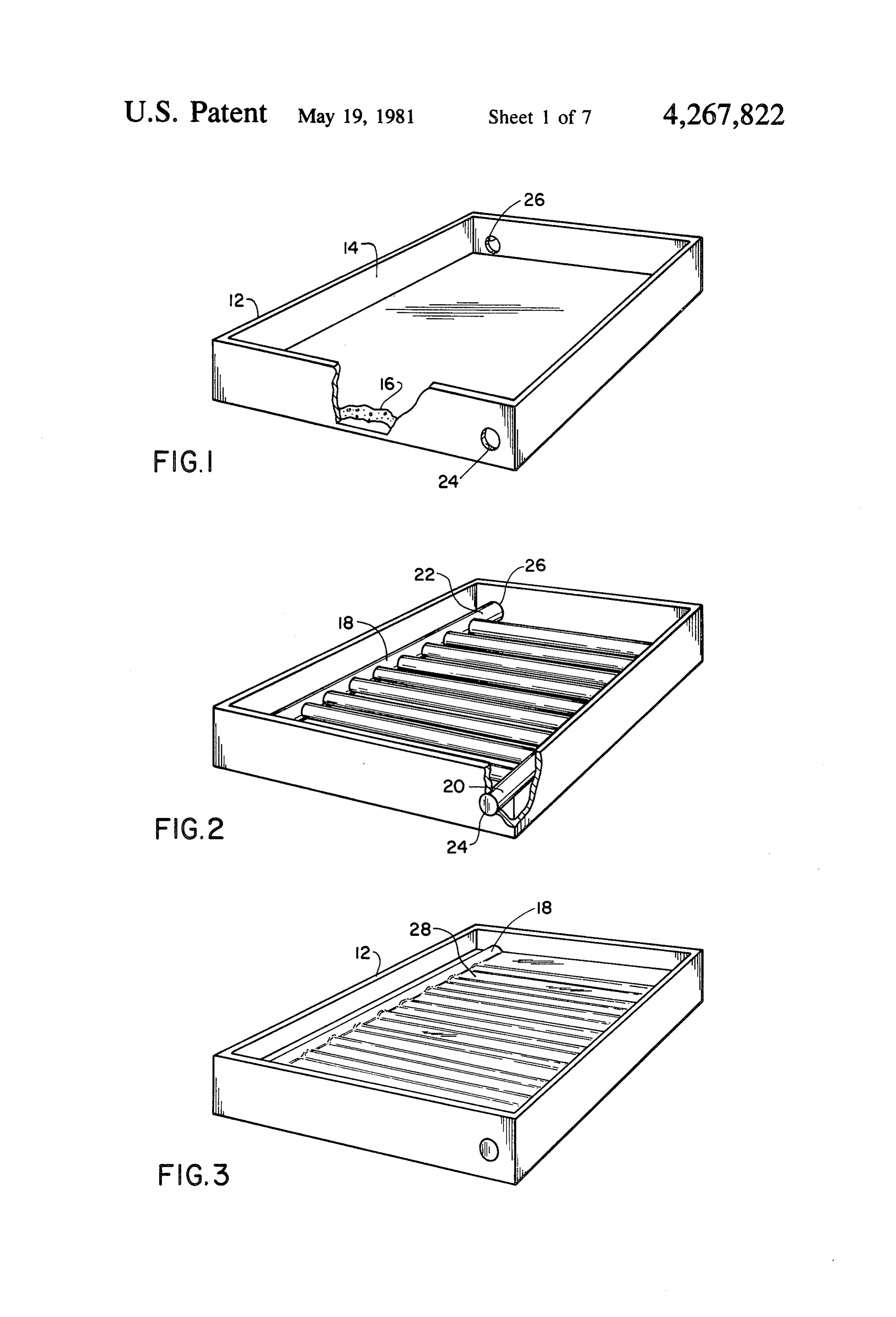
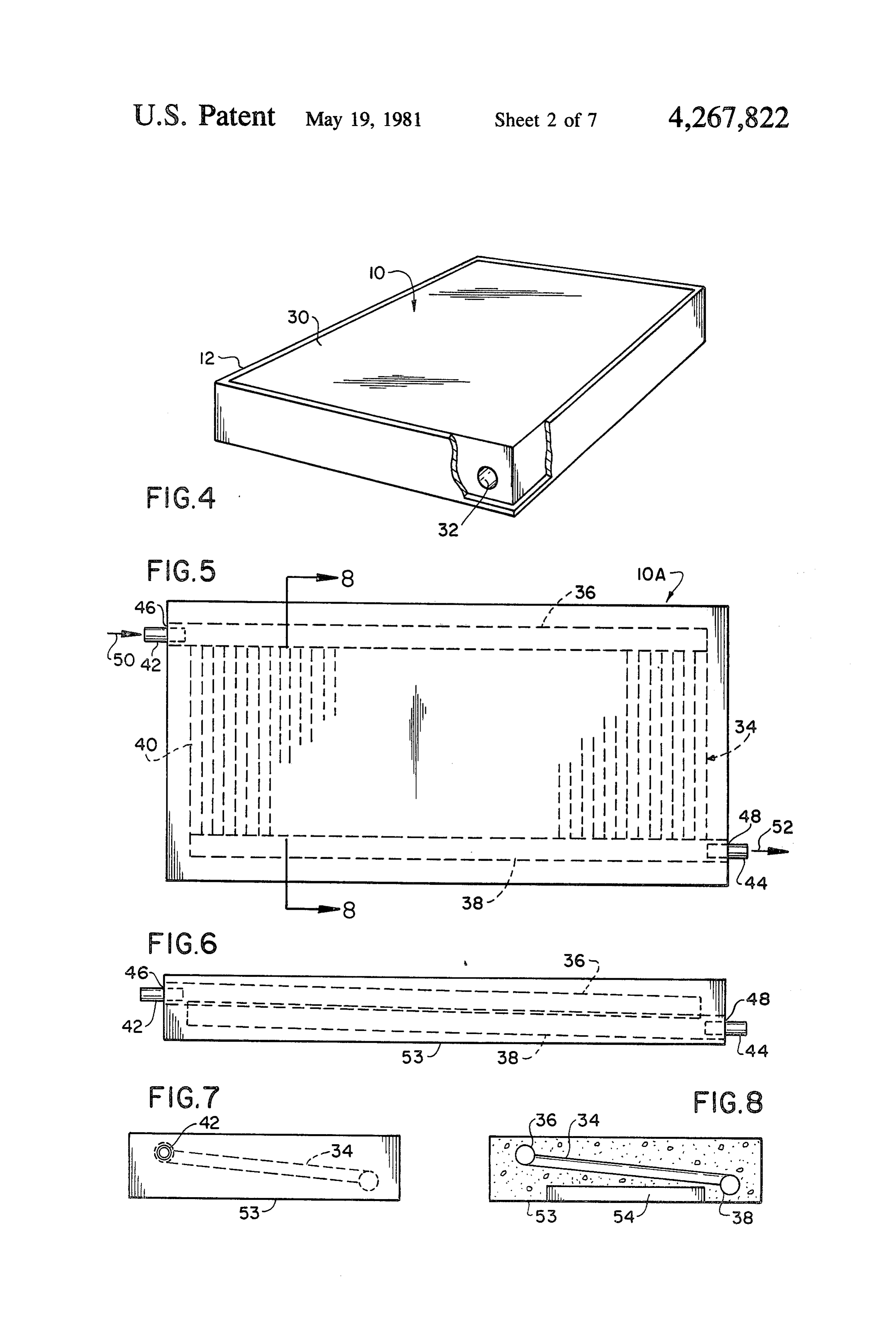
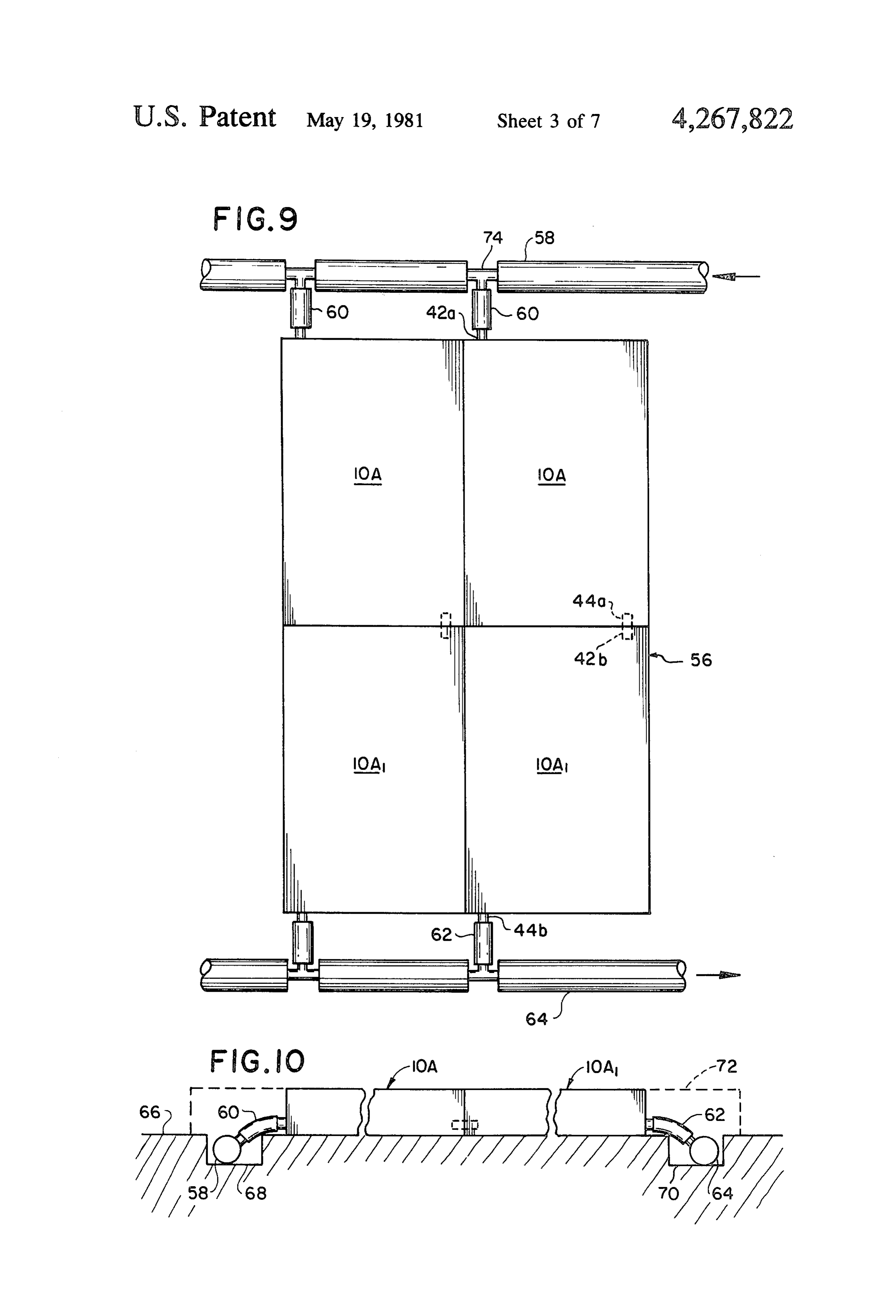
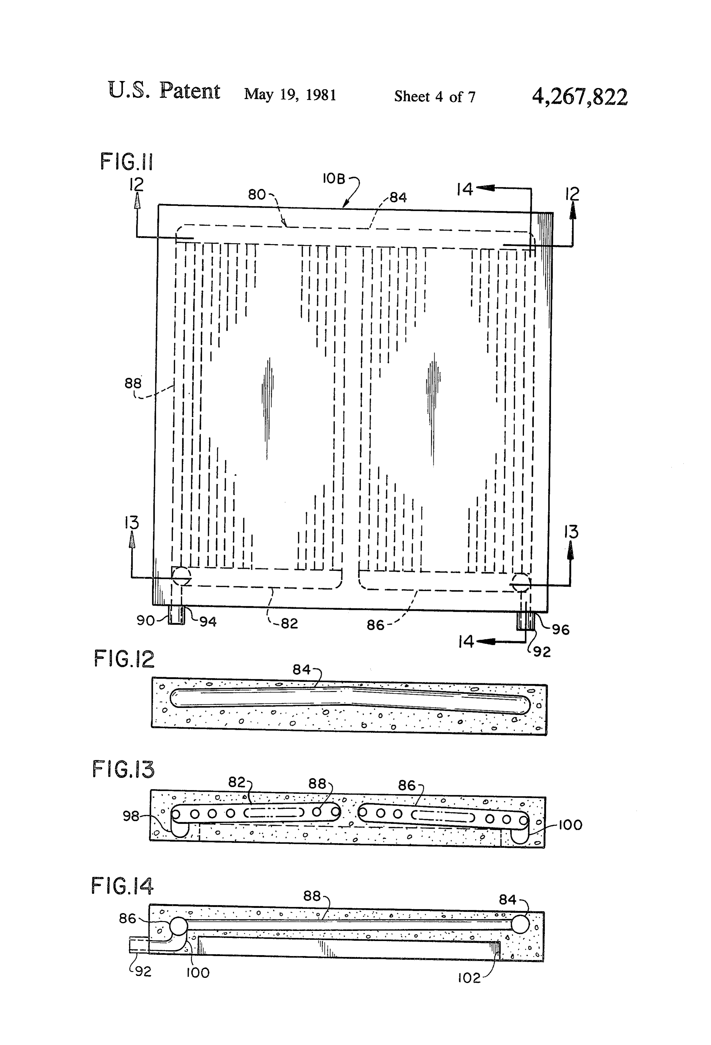
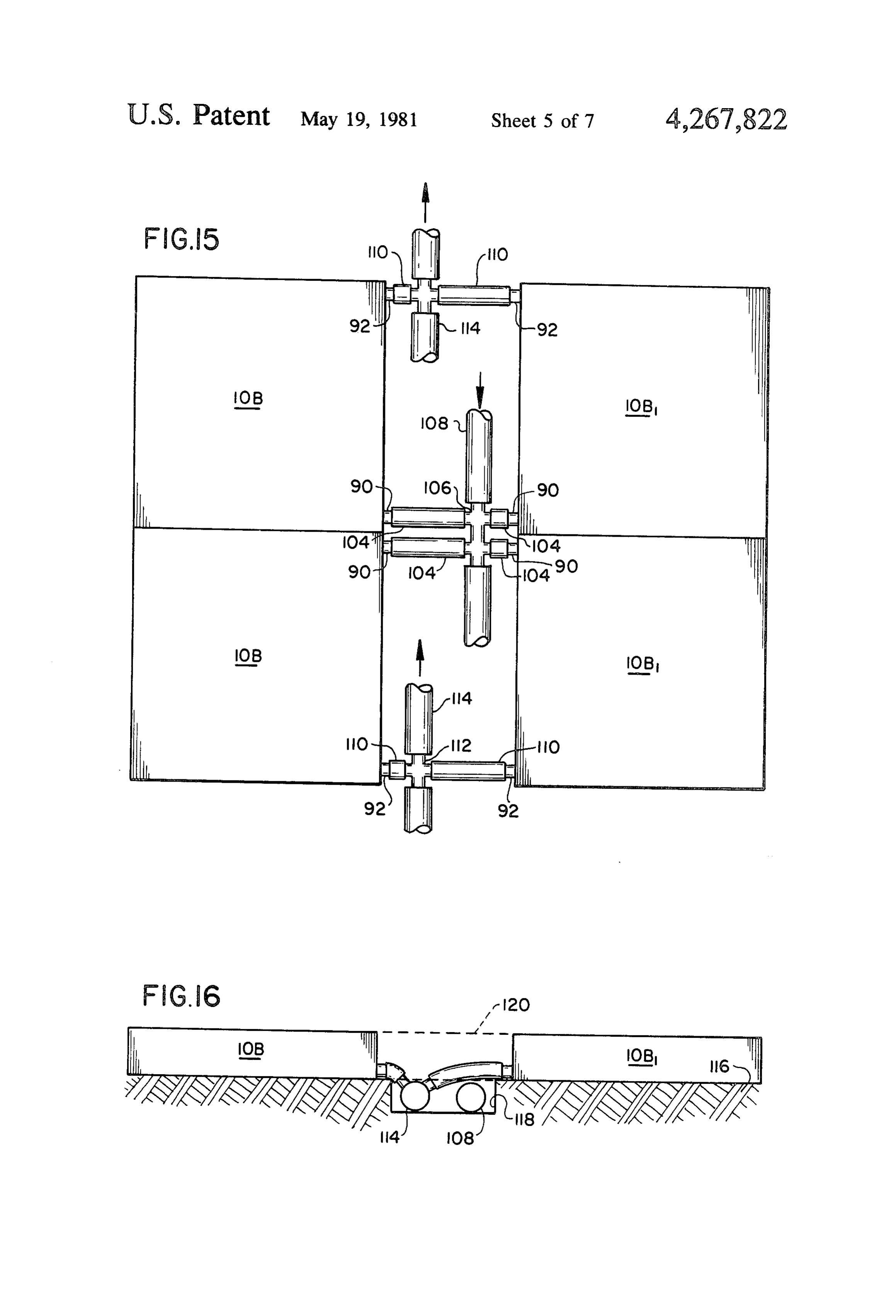
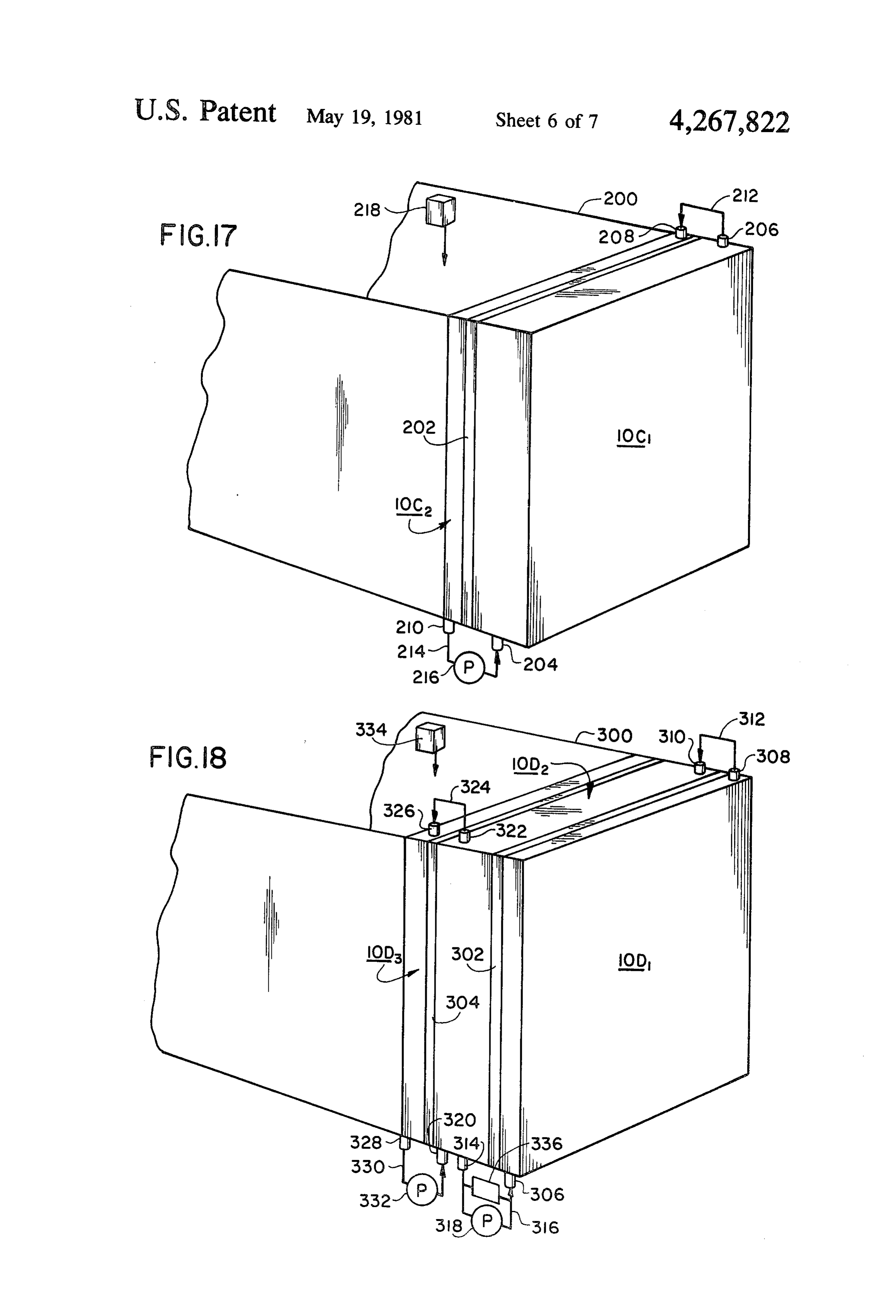
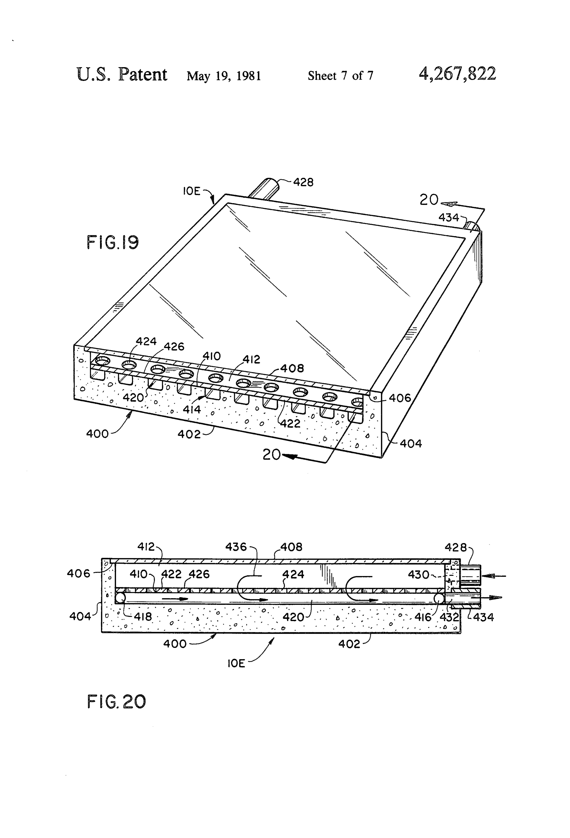
For the purpose of illustrating the invention, there is 10 with the process of the invention. Layer 16 is built up to shown in the drawings the forms which are presently the required thickness and for modules that will be used preferred; it should be understood, however, that the for horizontal floor elements and the like, the surface of invention is not necessarily limited to the precise ar the layer can be inclined appropriately such that the rangements and instrumentalities here shown. passageways to be produced in the module by the steps FIGS. 1-4 are perspective views partially in section 15 to be described are given the required slope to be gravi illustrating successive steps in the manufacture of solar tationally self-draining. Upon layer 16 (see FIG. 2) is collector modules in accordance with the invention; laid a preform 18 that is sized and shaped out of a dis FIG. 5 is a plan view of a solar collector module of solvable material such as expanded polystyrene in a the invention; pattern or configuration of the fluid passageway system FIG. 6 is a side elevational view of the solar collector 20 that is going to be formed in the module. The end sec module of FIG. 5; tions 20 and 22 of the preform that, in this embodiment, FIG. 7 is an end view of the module of FIG. 5; will form the inlet and outlet openings of the internal FIG. 8 is a transverse cross-sectional view, substan passageways of the finished module are aligned with tially on line 8-8 of FIG. 5; ports 24 and 26 respectively in the side of the mold 12. FIG. 9 is a diagrammatic plan view of an array of the 25 Then the voids around the various features of the pre modules of FIG. 5; form 18 are filled with a high cement-ratio sand con FIG. 10 is a diagrammatic side view of the array of crete 28 (FIG. 3). A top layer 30 of the cement mixture FIG. 9; is then poured or sprayed into the mold until the module FIG. 1 is a plan view of an alternate embodiment of 10 attains its final form and thickness. Following these a solar collector module of the invention; 30 steps, a solvent of the material of the preform 18, such F.G. 12 is a transverse cross-sectional view, substan as gasoline in the case of expanded polystyrene, for tially on line 12-12 of FIG. 11; example, is then introduced by any suitable means (not F.G. 13 is a transverse cross-sectional view, substan shown) through ports 24 and 26 in the mold 12 to dis tially on line 13-13 of FIG. 11; solve the preform to thereby leave voids that form the FIG. 14 is a transverse cross-sectional view, substan- 35 system of passageways 32 (see FIG. 4) in the module 10. tially on line 14-14 of FIG. 11; The module is then allowed to cure in the mold for an FIG. 15 is a diagrammatic plan view of an array of appropriate time, suitably about 16 hours. Following the modules of FIG. 11; this, the module is removed from the mold and is al FIG. 16 is a diagrammatic end view of the array of lowed to cure wet, preferably for about seven days. FIG. 15; 40 The spectral absorption of the surface of the module FIG. 17 is a diagrammatic view of modules of the 10 that will be exposed to insolation may be enhanced invention embodied in a building; by means generally known in the art such as by the FIG. 18 is a diagrammatic view of an alternate ar incorporation of additives in the casting material or by rangement of modules of the invention embodied in a the application of suitable known coatings to the sur building; 45 face. Means such as enlarged bores in the inlet and FIG. 19 is a perspective view partially in section of outlet portions of the passageways 32 in which nipples another alternate embodiment of a solar collector mod are fitted or other similar coupling expedients are sup ule of the invention; and plied as required such that individual collector modules FIG. 20 is a transverse cross-sectional view, substan can be interconnected for assembly into a system. It will tially on line 20-20 of FIG. 19. 50 be appreciated that the configuration of the internal DESCRIPTION OF THE PREFERRED labyrinthine passageways will be designed for maxi EMBODEMENTS mum efficiency for the application for which the mod ule is intended. Thus, the module can have a system of
The solar collector of my invention can be fabricated labyrinthine or sinuous passageways of various configu in any suitable manner by casting in a mold a concrete 55 rations and multiple rows forming more than one sys module having the required external configuration and tem of passageways in a single module can also be pro dimensions which has embedded therein a preform of vided.
dissolvable material that has been shaped into the de In operation, a number of collector modules 10 are sired configuration of the internal labyrinthine passage joined together in a desired configuration and are con ways of the collector and then dissolving the preform nected for fluid transmission by inserting nipples or material to produce a concrete collector module having other suitable coupling means in the inlet and outlet integral fluid passages. A preferred method of fabrica ends of the internal passageways 32 so that the modules tion is illustrated diagrammatically in FIGS. 1 through are in fluid communication with each other. The mod 4. Referring now to FIG. 1, into an open-topped form ules can be connected in parallel, that is, all the outlet or mold 12, having an interior cavity 14 whose dimen 65 conduits are connected to one another and all the inlet sions and shape will produce a product of the desired conduits are connected to one another, or they can be final shape and size and whose surfaces will impart to series connected with the outlet of one module being the molded material the desired surface finish, is connected to the inlet of the adjoining module, such 11 that a desired pattern of fluid flow through the array of flow passes out of the respective outlet nipples 44b to modules is established. Other suitable means for inter outlet pipes 62 and is returned by a means of return pipe connecting the inlet and outlet conduits may be used 64 to the swimming pool carrying the heat that had according to techniques well-known in the art. By suit been imparted to it by solar insolation in the collector ably coupling appropriate modules in a vertical contigu- 5 modules.
ous orientation a system can be produced for use as a The collector modules can be provided with a suit structural wall of a building which will also function to able foundation 66 or may rest directly on the earth collect solar energy and store it and subsequently radi (FIG. 10). Runs or troughs 68 and 70 accommodate the ate it on demand for utilization in the building. Coupling supply pipe 58 and the return pipe 64 respectively. Con together a plurality of collector modules in a horizontal 10 crete blocks 72 having appropriate clearance areas orientation permits an array of collectors of virtually molded therein can be used to conceal and protect the any size or configuration to be constructed. It should piping of the system. It will be appreciated that the also be understood that the peripheral configuration of necessary T-fitting 74 and other well known compo the individual modules is not necessarily limited to or nents (not shown) of a solar collector system are pro thogonal shapes, such as a square or rectangle, because 15 vided as required to ensure efficiency in operation. the casting process permits any required shape to be A further embodiment of the solar collector module employed so that collector assemblies using a number of such modules may be assembled into an array having of this invention which has the inlet and outlet ports on the same side is shown in FIGS. 11-14. As has been any desired configuration.
The structural properties and the material of con- 20 stated with respect to module 10A, the collector mod struction of the collectors of this invention give the process ofofthis ule 10B this embodiment is suitably made by the invention in a rectangular shape which collector modules characteristics that make them suit able for use as paving units through which hot fluids internal water passagewaysoverall can have any appropriate size. The module has comprising an inlet mani can be circulated to melt ice and snow in winter or for use as solar collectors in summer. An application of the 25 and transverse passages 88 connecting themanifold fold 82, a transfer manifold 84, an outlet inlet mani modules that is particularly suitable is their use around swimming pools as walks or patios that also function as fold to to the transfer manifold and the transfer manifold the outlet manifold. Nipples 90, 92 or other suitable solar collectors to warm the water in the pools. An coupling means are provided at the inlet 94 of the inlet embodiment of the solar collector of this invention manifold 82 and at the outlet 96 respectively of the suitable for such application is illustrated in FIG. 5. 30 outlet manifold.
Collector module 10A embodied therein suitably is As in the FIG. 5 embodiment of the made by the process of the invention in a rectangular collector module, the internal passageways are sized planar shape which can have any appropriate overall and shaped for uniform flow distribution and good heat size. The module has a system of internal labyrinthine transfer characteristics and also they are sloped appro water passageways 34 comprising an inlet manifold 36, 35 priately to allow for gravitational self-draining of the an outlet manifold 38, and transverse passages 40 join module's passageways. Thus, inlet manifold 82 is sloped ing the two manifolds. Passages 40 are closely spaced in the direction of inlet 94, outlet manifold 86 is sloped for good heat transfer. Nipples 42, 44 or other suitable in the direction of outlet 96 (see FIG. 13) and transfer coupling means are provided at the inlet 46 of the inlet manifold 84 has an inverted, very shallow 'V' shape manifold 36 and at the outlet 48 respectively of the 40 with the apex thereof having a higher elevation than the outlet manifold. The internal passageways are shaped ends of the legs of the "V" as shown in FIG. 12. In and sized in accordance with good design practice for addition, as indicated in FIG. 14, the transverse pas uniform flow distribution and the transverse passages sages 88 are sloped downward from the transfer mani are closely spaced for good heat transfer. In addition, as fold 84 in the direction of the inlet and outlet manifolds. indicated in FIGS. 6-8, the inlet port 46 of the module 45 Also, as indicated in FIG. 13, the inlet and outlet por is at a higher elevation than the outlet 48 and both of the tions of the internal passageways 80 have a short verti internal manifolds and the transverse passages are cal section 98 and 100 respectively to allow clearance sloped downward in the direction of flow (indicated by for a recess 102 in the bottom of the module if such directional arrows 50, 52) to allow for gravitational expedient is adopted for weight reduction. draining of the internal passageway system. This self. 50 Module 10B can be connected together with like draining feature allows daily drainback of the system elements as has been described previously for the mod when the pump is off and thus precludes the possibility ule embodied in FIG. 5. The modules 10B would be of the freezing of standing water in the system by a drop assembled (see FIG. 15) with their inlet nipples 90 con in temperature. The bottom 53 of the module 10A can nected to inlet pipes 104 which are coupled by means of be provided with a recess 54 as a weight reduction 55 T-fittings 106 to a supply pipe 108 which connects to a eaSule. swimming pool or other source of water (not shown) Module 10A can be connected together with like which it is desired to heat, and their outlet nipples 92 elements to form a patio or deck 56 surrounding, for connected to outlet pipes 110 which are coupled by example, a swimming pool (not shown) as illustrated in means of T-fittings 112 to a return pipe 114 by which FIGS. 9 and 10. Water from the swimming pool is 60 the water pumped through the system is returned to the pumped through a supply pipe 58 and inlet pipes 60 and swimming pool carrying the heat which has been im passes into the first row of collector modules 10A parted to it by insolation in the solar collectors. The through inlet nipples 42a. Passing through the collec collector modules can be provided with a suitable foun tors and being heated by solar energy as it does, the dation or may rest directly on the ground 116. A trough water flows out of outlet nipples 44a and into the sec- 65 or run 118 is provided to accommodate the supply 108 ond row of collector modules 10A by means of inlet and return 114 pipes. Concrete blocks 120 having ap nipples 42b. From the second row of collectors (or propriate clearance areas provided therein and sized to Subsequent rows if more than two are provided) the fit over the pipe trough 118 are laid between the rows of 12 collector modules to conceal and protect the piping of an inlet pipe 310 connected to the outlet 308 of the outer the system (FIG. 16). collector module by means of ducting 312 and an outlet FIG. 17 illustrates the solar collector modules of this pipe 314 connected to the inlet 306 of the outer module invention utilized as structural wall members of a room by ducting 316. A pump or fan 318 is provided in duct 200 of a building (not shown). In this embodiment, 316 for circulating fluid between the collector and the module 10C1 is used as the outer wall of the room, storage modules. Storage module 10D2 also has a sec functioning as a solar collector and storage unit, and a ond inlet pipe 320 and a second outlet pipe 322. The second module 10C serves as the inside wall. The outer outlet 322 is connected by means of ducting 324 to the and inside walls preferably are separated by a layer 202 inlet pipe 326 of the inside module 10D3 which also has of thermal insulation. Outer module 10C has an inlet 10 an oulet pipe 328 connected to inlet pipe 320 of storage pipe 204 connected to the internal passageways thereof module 10D2 by means of ducting 330. A pump or fan and an outlet pipe 206 therefrom, and inside module 332 is provided in duct 330 for circulating fluid between 10C2 has an inlet pipe 208 and an outlet pipe 210 con the inside and intermediate modules. The storage mod nected to its system of internal passageways. Appropri ule is cored to have two separate passageway systems ate piping or ducting 212 couples the outlet of the outer 15 such that fluid circulated in the first passageway system module to the inlet of the inside module and piping or from the outside collector module 10D1 by pump 318 is ducting 214 couples the outlet of the inside module to in heat exchange relationship with but does not contact the inlet of the outside module. A pump 216, if the the fluid in the second passageway system circulated working fluid of the system is a liquid or a fan if the fluid from the inside module 10D3 by pump 332. With such is air is located in ducting 214 and a thermostat 218 for 20 an arrangement in which the fluid from the outer mod effecting the operation of the pump in suitably installed ule does not contact the fluid used in the inside wall in room 200. A suitable electrical power source for the module, it is feasible to use air or a non-freezing (at the fan or pump and associated electrical circuitry and expected temperatures) liquid in the outside internal control means are provided; such components and oth passageway system and water or the like in the inside ers of a solar heating system such as an expansion tank, 25 internal passageway system. A thermostat 334 for ef check valves, freeze dump valves, can be provided as fecting the operation of pump 332 is suitably installed in required. Inasmuch as these ancillary components are room 300, and control of pump 318 as a function of the well known and in common use in the art, in the inter relative temperature of the fluid in the collector module ests of clarity and brevity they are not shown and will 10D1 with respect to the fluid in the storage module not be described further. 30 10D2 is accomplished by temperature sensing means In operation, the working fluid in the internal pas 336. A suitable electrical power source for the pumps sageways (not shown) of the outer wall module 10C is and associated electrical circuitry and control means are heated by the sun. When the room thermostat 218 calls provided. As has been stated with regard to the FIG. 17 for heat, the pump 216 is actuated such that solar-heated embodiment of the invention, such components and fluid from collector module 10C is delivered through 35 others of solar heating systems per se are well known ducting 212 to module 10C2. The heated fluid circulat and are in common use and it is believed, therefore, that ing through the internal passageway system (not no useful purpose will be served by showing or describ shown) of module 10C2 transmits heat into room 200 by ing them herein.
free convection and radiation. After passing through In operation, the working fluid in the internal pas the inner wall module, during which time it has lost 40 sageway system (not shown) of the collector module heat, the fluid is returned by pump 216 through duct 214 10D is heated by the sun. When the temperature of the to exterior wall module 10C1 for re-heating. fluid in the collector exceeds that of the fluid in the A further embodiment of the modules of this inven storage module, the pump 318 is activated to circulate tion incorporated in a structural system is illustrated in the fluid into the first passageway system in the storage FIG. 18. In this embodiment, the modules are used as 45 module for storage therein. When the room thermostat structural wall members of a room 300 of a building (not 334 calls for heat, the pump 332 is activated such that shown). An outer module 10D1 functions as a solar solar-heated fluid in the second passageway system collector and storage unit, an intermediate module (which is in heat exchange relationship with the first 10D2 is a energy storage unit, and module 10D3 serves passageway system and is heated thereby) of the storage as the inside wall element of the room 300. The storage 50 module is delivered through ducting 324 to the inside module 10D2 can be thicker than either the collector or wall module 10D3, where the heated fluid transmits the inner wall module such that a greater "density' of heat into room 300 by free convection and radiation. internal passageways can be provided to increase Pump 332 circulates fluid between the storage and the thereby the thermal storage capacity of the unit. As is inside wall modules as required to maintain the fluid at well known, the passageways of the storage module can 55 the desired temperature.
be filled with bodies such as stones or rocks or other FIGS. 19 and 20 illustrate a further embodiment of a media to increase the amount of heat stored. As is also solar collector module 10E constructed in accordance known, other heat storage materials such as those that with this invention. Module 10E has a generally flat undergo a change of state can be used. Known materials rectangular configuration and has a body 400 which is include inexpensive eutectic, phase-change salts such as, 60 preferably cast or molded out of cement by the process for example, sodium sulfate decahydrate, and the like. of this invention. The cement can also contain light The outer module and the inside module preferably are weight aggregates and other additives to reduce the separated from the intermediate storage module by weight of the structure or to provide other desired layers 302 and 304 respectively of suitable thermal insu properties. The body 400 comprises a base 402 portion lation. 65 and an integral peripheral wall 404 extending around Outer collector module 10D1 has an inlet pipe 306 the sides thereof. A shoulder 406 extending around the connected to the internal passageways thereof and it has upper periphery of wall 404 provides a ledge upon an outlet pipe 308 therefrom. Storage module 10D has which a sheet 408 of transparent material rests. Any 13 suitable sealing means (not shown) may be used to re port, said heat is transferred outside of said module for tain the sheet 408 and to provide a hermetic seal be utilization.
tween the edges thereof and the shoulder 406. Sheet 408 2. In a solar heating system for a building, a first and forms the cover of the collector and between it and the a second contiguous module defining a structural wall recessed upper surface 410 of the base 402 is defined a of a room in said building, said first module forming the outer element and said second module forming the inner chamber 412. Molded into surface 410 are a pattern of fluid channels or passageways 414 having manifolds 416 tweenelement of said wall, a layer of thermal insulation be and 418 across the ends, which manifolds are connected said first and second modules, each of said mod by a multiplicity of passages 420. Resting on surface 410 O ules having a cast concrete body with a system of laby is a metal absorber plate 422 which is provided with a rinthine, interconnected internal passageways therein, multiplicity of perforations 424 or through holes which said passageways being closely spaced for good heat preferably are aligned with passages 420. The absorber transfercharacteristics, therebetween and having uniform flow distri surface 426 is made spectrally absorptive by suitable bution inlet and outlet means for said means as by known coatings applied to the surface as is 5 of the module for the induction and with internal passageways communicating the outside the eduction of common in the art. An inlet nipple 428 and inlet port fluid, fluid coupling means connecting the outlet and 430 are provided for the admittance of fluids into col inlet of said first module to the inlet and outlet respec lector chamber 412 and an outlet port 432 and nipple tively of said second module such that fluid can be 434 are provided for the discharge of fluids from the circulated through and between said modules, a pump collector.
In operation, a circulation of fluid as indicated by 20 in the fluid coupling means connecting the outlet of said second module with the inlet of said first module to directional arrows 436 through the solar collector mod effect said circulation of said fluid, a control system for ule 10E is provided by fluid that enters collector cham controlling the operation of said pump as a function of ber 412 through inlet port 430 and passes into channels temperature, said control system having a thermostat 414 through perforations 424 in absorber plate 422 and 25 installed in said room, internal passageways of said first exits from the collector through outlet port 432. Solar module being in good heat exchange relationship with a energy, passing through the transparent cover plate 408 surface thereof exposed to insolation such that when is absorbed by absorber plate 422 to thereby heat it. This said module is absorbing solar radiation the fluid therein heat is imparted to the fluid circulating through the is heated, internal passageways of said second module collector module and the fluid transmits the heat to a 30 being in good heat exchange relationship with the sur suitable heat exchanger for utilization. face thereof defining a wall of said room, said control It will be appreciated that the solar collector of this system activating said pump when said thermostat calls embodiment, as is the case with the other modules em for heat whereby heated fluid is circulated out of said bodied in the invention, can be installed for use either first module to said second module to thereby condition horizontally or vertically or any desired orientation 35 the temperature of said room by free convection and therebetween. In addition, instead of only a single sheet radiation.
408 of transparent material, a double sheet can be em 3. In a solar heating system for a building, first, inter ployed as is well known in the art. mediate, and third contiguous modules defining a struc Although shown and described in what are believed tural wall of a room in said building, said first module to be the most practical and preferred embodiments, it is 40 forming the outer element and said third module the apparent that departures from the specific method and inner element of said wall, a layer of thermal insulation apparatus described will suggest themselves to those at least between said intermediate and said third mod skilled in the art and may be made without departing ules, each of said modules having a cast concrete body, from the spirit and scope of the invention. I, therefore, the first and third modules having a single and the inter do not wish to restrict myself to the particular instru 45 mediate module a first and a second system of labyrin mentalities illustrated and described, but desire to avail thine, interconnected internal passageways therein, said myself of all modifications that may fall within the com passageways being closely spaced for good heat transfer pass of the appended claims. therebetween and having uniform flow distribution Having thus described my invention, what I claim is: characteristics, inlet and outlet means for each of said 1. A solar collector module comprising a cast con 50 systems of internal passageways communicating with crete body, a recess in the upper surface of said body, a the outside of the module for the induction and eduction plate transparent to solar radiation covering said recess of fluid, fluid coupling means connecting the outlet and in a sealed relationship therewith, the floor and walls of inlet of said first module to the inlet and outlet respec said recess with said transparent plate defining a her tively of the first passageway system of said intermedi metic chamber in said body, a pattern of labyrinthine 55 ate module and fluid coupling means connecting the interconnected channels in the floor of said recess, a outlet and inlet of the second passageway system of said perforated metal absorber plate on said floor overlying intermediate module to the inlet and outlet respectively said channels, at least some of the perforations in said of said third module such that fluid can be circulated absorber plate being aligned with said channels, said through and between said modules, a first pump in the metal plate absorbing solar energy passing through said 60 fluid coupling means connecting the outlet of said first transparent plate, an inlet port opening into said her passageway system of said intermediate module with metic chamber, an outlet port opening on said channels, the inlet of said first module and a second pump in the said ports communicating with the outside of said mod fluid coupling means connecting the outlet of said third ule, whereby the circulation of fluid through said inlet module with the inlet of said second passageway system into said chamber and through said perforations in said 65 of said intermediate module to effect the circulation of metal plate imparts heat to said fluid when said metal said fluid, a control system for controlling the operation plate is absorbing solar energy such that, when said of said pumps as a function of temperature, said control heated fluid passes into said channels and out said outlet system having a thermostat installed in said room and 14 relative fluid temperature sensing means for sensing the said intermediate module being in heat exchange rela temperature of the fluid in said first module and said tionship with and heating the fluid in said second pas first passageway system of said intermediate module, sageway system therein, internal passageways of said internal passageways of said first module being in good third module being in good heat exchange relationship heat exchange relationship with a surface thereof ex with the surface thereof defining a wall of said room, posed to insolation such that when said module is ab said control system activating said second pump when sorbing solar radiation the fluid therein is heated, said said thermostat in said room calls for heat whereby control system activating said first pump when the tem heated fluid is circulated out of said intermediate mod perature of the fluid in said first module exceeds that of ule to said third module to thereby condition the tem the fluid in said first passageway system of said interme O perature of said room by free convection and radiation. diate module such that said heated fluid is circulated 4. The solar heating system of claims 2 or 3 wherein into said intermediate module for storage therein, said the modules have a substantially planar surface. stored heated fluid in said first passageway system of k
Provenance
- Collection
- Patents citing this work
- Pages
- 14
- Method
- pdftotext (the PDF's own text layer) + pdftoppm 300dpi page scans
- Patent office record
- patents.google.com →
- Source
- Google Patents citing-documents table
- Assignee
- Grumman Energy Systems, Inc.
- Published
- 1981-05-19
- Transcribed from
- patentimages.storage.googleapis.com →