

patent · US4278418A
Process and apparatus for stoichiometric combustion of fuel oil
14 July 1981
Text
Page 1bibliographic recordscan →
United States Patent (19)
Strenkert
54 - PROCESS AND APPARATUS FOR
STOICHOMETRIC COMBUSTION OFFUEL
OIL 76 Inventor: Lynn A. Strenkert, 16 Azalea La.,
Wilton, Conn. 06897
Related U.S. Application Data 63 Continuation of Ser. No. 640,978, Dec. 15, 1975, aban doned.
Int. Cl. ................................................ F23C5/00 52 U.S. C. ........................................ 431/8; 239/422;
2,259,011 10/1941 Taylor .................................. 299/130
2,643,916 6/1953 White et al. ......................... 299/141
3,062,273 11/1962 Colin-Smith ..................... 239/422 X 3,078,047 2/1963 Enemark .............................. 239/103
3,203,769 8/1965 Sogawa et al. ........................ 23/277 3,245,457 4/1966 Smith et al. ..................... 431/352 X
3,254,846 6/1966 Schreter et al. ..................... 239/400
3,360,201 12/1967 Popyk .............................. 239/422 X
3,362,647 1/1968 Davis, Sr. et al. ................... 239/404 3,490,230 1/1970 Pillsbury et al..... . 60/39.65 3,705,784 12/1972 Reihhelm ......... . 431/116 3,741,483 6/1973 Kawaguchi. - - - - - - - - - 239/400 3,764,069 10/1973 Runstadler et al. ..................... 239/8 3,831,854 8/1974 Sato et al. ........ 431/352 X 3,870,456 3/1975 Graat ....................................... 431/8
Primary Examiner-Edward G. Favors
Attorney, Agent, or Firm-St. Conge, Steward, Johnston, Reens & Noé
A process and apparatus for the combustion of liquid fuel provides an extremely intense blue/violet flame having a temperature in excess of 3000' F. with combus tion under near perfect stoichiometric conditions with out the formation of soot. The liquid fuel is atomized and mixed with air within a nozzle and enters a flame tube surrounding the nozzle as a conical stream where it is further atomized by jets of air directed to converge on the stream and mixed with secondary combustion air to obtain the desired combustion mixture. Yet further at omization of the liquid fuel-air mixtures within the flame tube can be obtained as a consequence of at least partial vaporization of the liquid fuel therein through the heat of the flame tube. An advantageous relation ship exists between the size, angle and point of conver gence of the air jets with the atomized conical stream, the flame tube diameter and length and the location of the nozzle therein and the fuel feed.
22 Claims, 20 Drawing Figures
Drawings
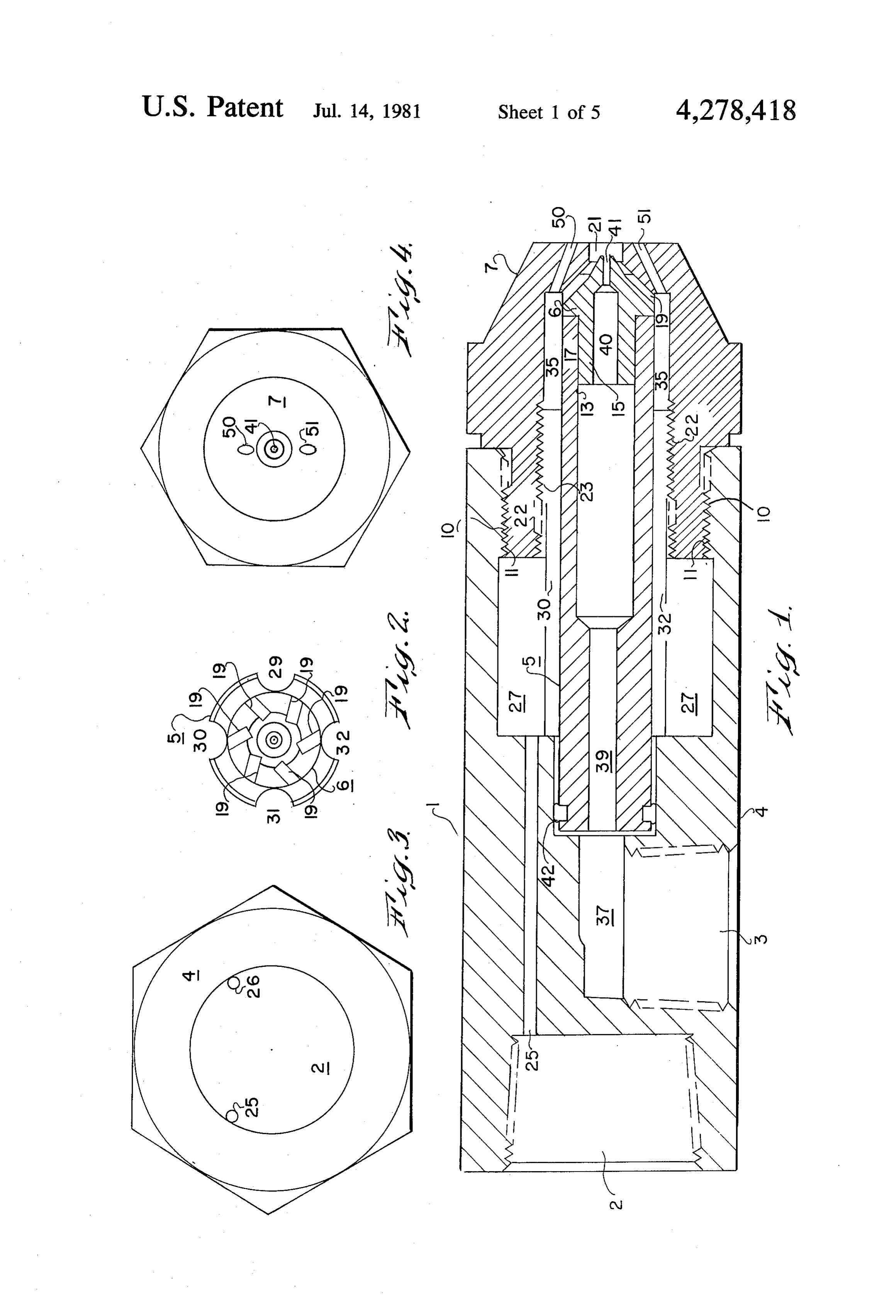
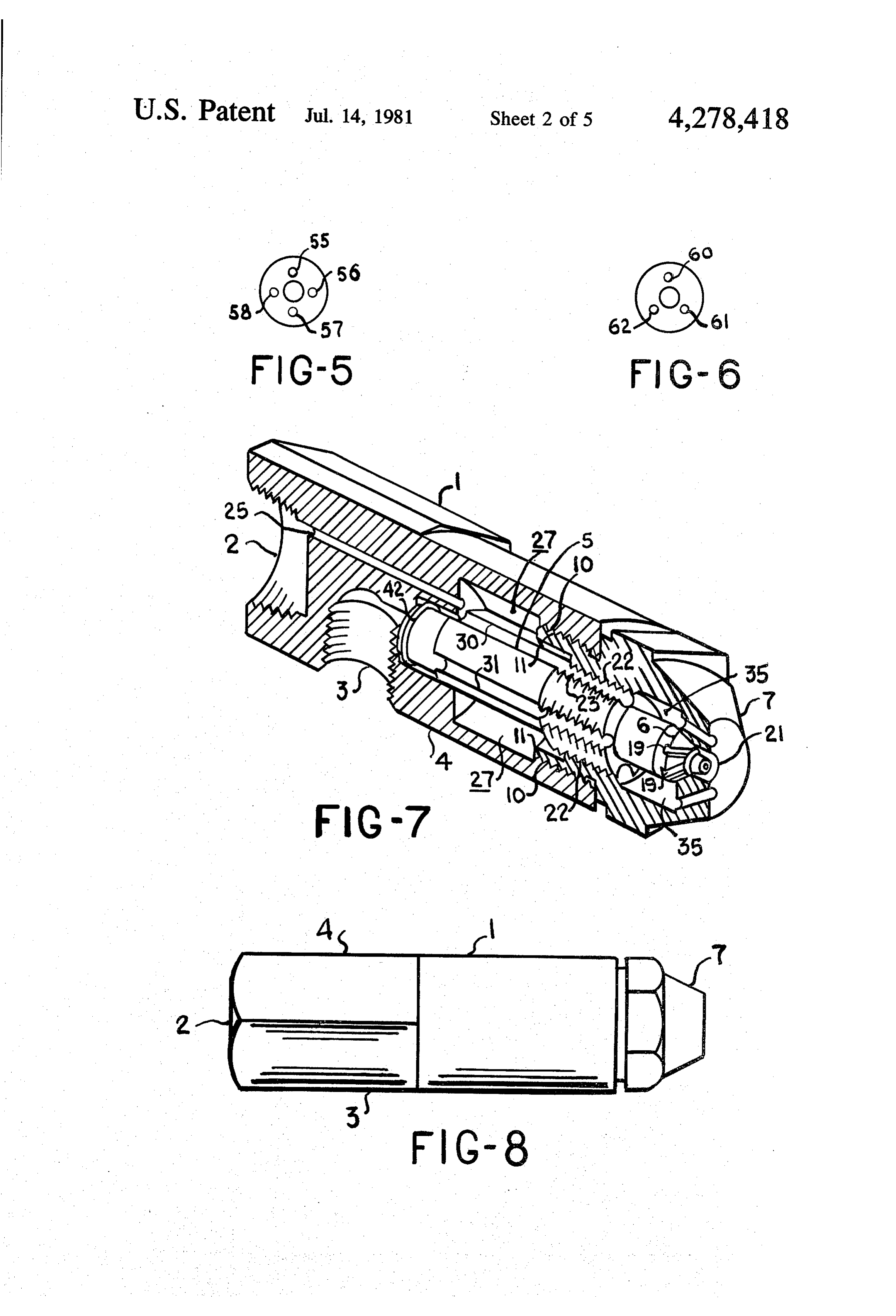
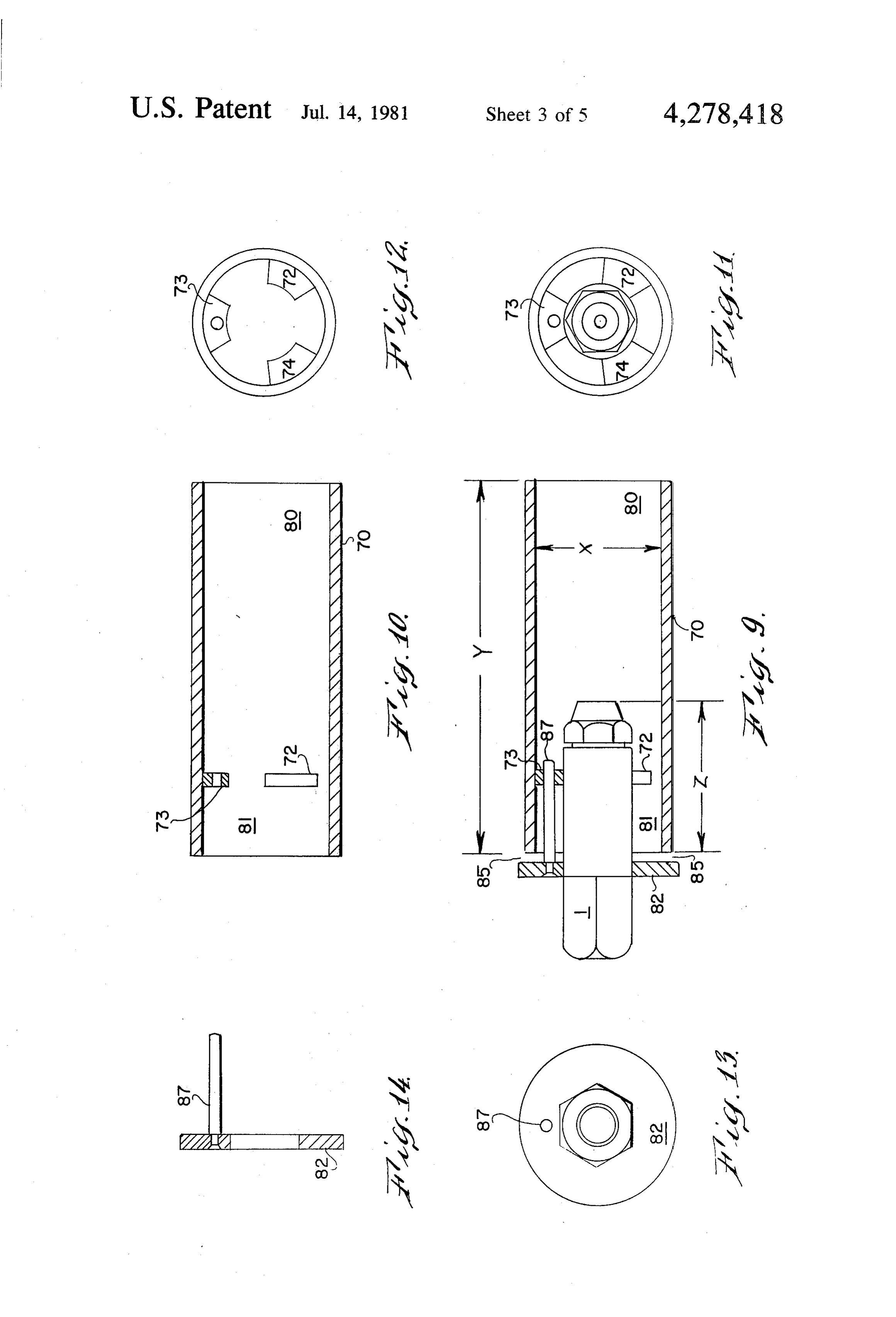
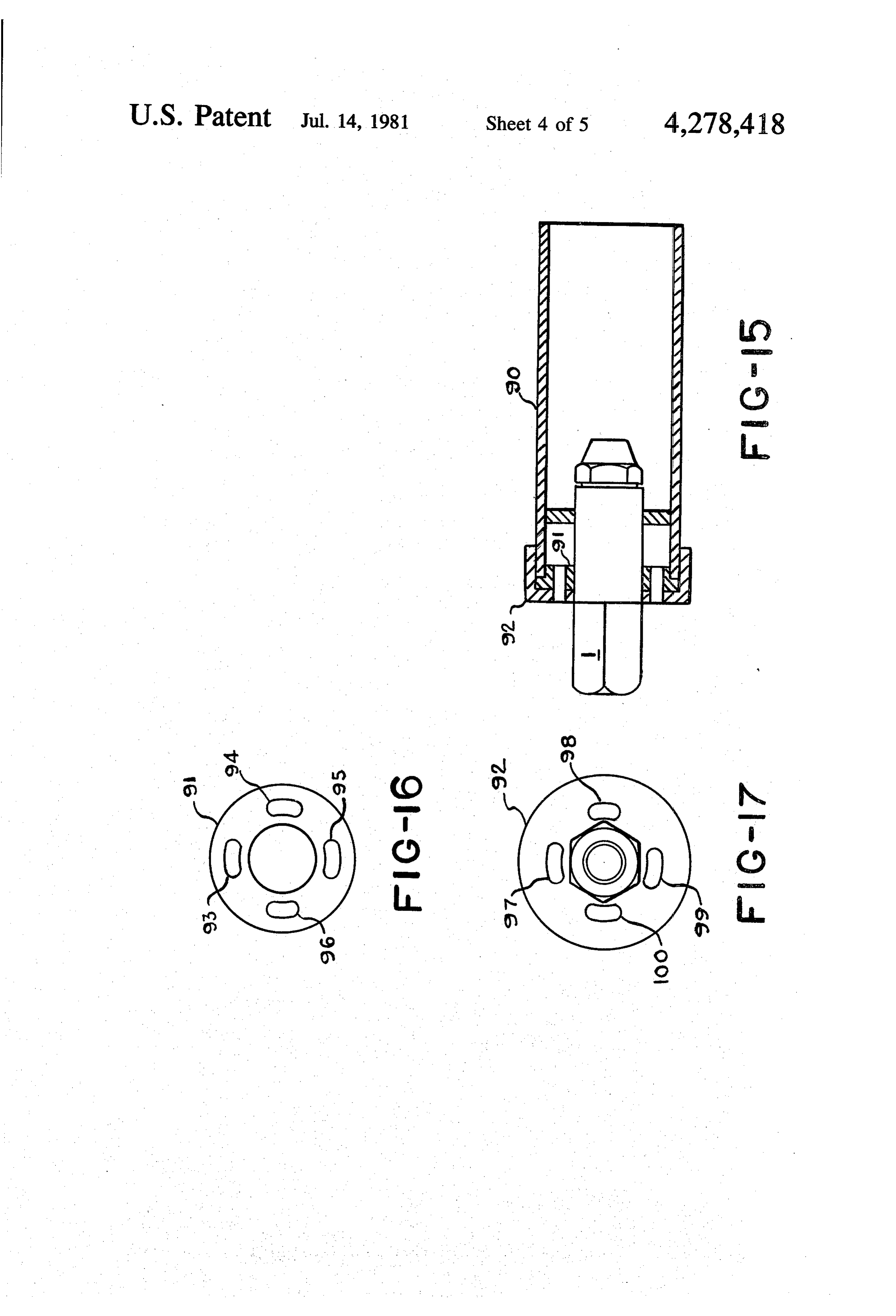
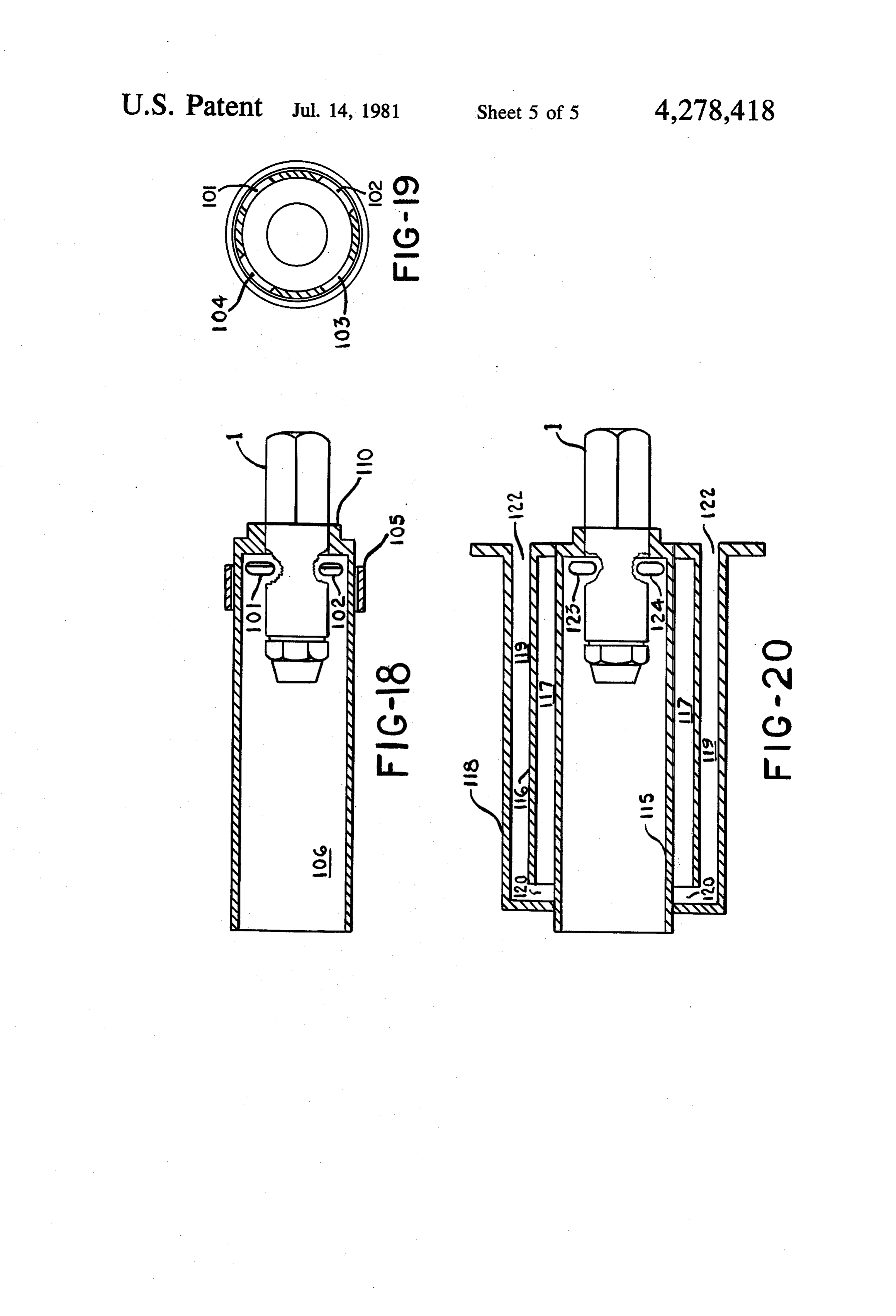
FIG. 8 is a side view of the nozzle structure of FIG.
Page 2drawing sheetscan →
Page 3drawing sheetscan →
Page 4drawing sheetscan →
Page 5drawing sheetscan →
Page 6drawing sheetscan →
Page 7scan →
in size; specifically, the droplets in the present invention
PROCESS AND APPARATUS FOR are from one-fifth to one-tenth the size of oil droplets STOICHOMETRIC COMBUSTION OF FUEL OIL that are the product of conventional atomization tech niques; and (3) the heat of the mixing tube surrounding
This application is a continuation of copending appli the nozzle further atomizes the sub-micron oil droplets cation Ser. No. 640,978 filed Dec. 15, 1975 abandoned. by vaporization of the finely atomized particles of oil. BACKGROUND OF THE INVENTION One important aspect of the invention is that the atomization is accomplished by a very small volume of
The present invention relates to a process and appara air that is under moderate pressure. The atomizing air tus for the combustion of liquid fuels, especially fuel oil O provides both suction to lift the fuel oil into the nozzle Numbers 2 through 4. Further, the present invention and the energy to pre-atomize the fuel within the noz relates more particularly to an oil atomizing burner that zle. Further, an air jet from the air source is injected uses low pressure air as the primary and secondary into the mixture of atomized fuel and air to create sec atomizing medium. ondary atomization
There are known combustion processes and burners 15 The mixing chamber controls the amount of combus by which fuel oils are atomized with air. Prior art burn tion air that is introduced into the area surrounding the ers are not adapted to produce perfect or near perfect flame and thus controls the stoichiometric mixture of combustion. As a result, soot and carbon are formed the fuel oil and air.
which has a further detrimental effect on the burner Accordingly, it is an object of this invention to pro operation as the soot and carbon contaminate the noz 20 vide a device for the combustion of liquid fuels which zle, combustion chamber and other heat-exchange sur operate at near perfect combustion conditions without faces. The present invention, by producing complete the production of soot.
combustion, eliminates the formation of soot. It is a further object of this invention to provide a One of the more advanced designs for burners prior device which produces a high heat release blue/violet to the present invention is shown in U.S. Pat. No. 25 flame having an intense temperature of over 3000' F. 3,362,647 to Davis et al. That patent discloses a burner without the use of pre-heated air. A further object of spray nozzle which utilizes fuel oil under pressure this invention is that the high heat release flame is pro which is thereafter mixed with normally aspirated air. duced by moderate pressure air which can be easily In the present invention, the atomized air is under pres provided at a low cost.
sure and the fuel is not. These are burners which do, 30 An additional object of this invention is to provide a however, utilize low pressure air for atomization pur burner that very finely atomizes a variety of fuel oils for poses as well as to draw the fuel into the mixing cham better combustion. Another object of this invention is to ber. Such a design is shown in Schreter et al, U.S. Pat. provide a burner that produces an extremely intense, No. 3,254,846. The Schreter patent does not utilize the but yet short flame.
construction of the present nozzle which has been de 35 A further object is to provide a burner of simple signed to swirl the fuel-air mixture to increase the atom construction which can be economically manufactured ization process. Further Schreter does not disclose the and operated with a minimal amount of maintenance. use of a flame tube or secondary atomization which is These and other objects and advantages of the pres utilized by the present invention. Another prior art ent invention will be more readily apparent from the construction which is of possible interest is disclosed by 40 following detailed description of the drawings illustrat Graat, U.S. Pat. No. 3,870,456. This prior art reference ing the preferred embodiment of the invention. does not disclose the present invention as it utilizes an BRIEF DESCRIPTION OF THE DRAWINGS entirely different nozzle structure wherein the fuel is under pressure. Further, the Graat reference does not In the drawings:
disclose any secondary or tertiary atomization. 45 FIG. 1 is a sectional view of the nozzle utilized by the The burners disclosed in the above references are present invention.
similarly deficient when contrasted to the present in FIG. 2 is a frontal view of the convoluted impeller vention, that is, they do not produce an extremely in and nozzle of the present invention. tense, short-length flame. Further, the present invention FIG. 3 is the left side or rear of the nozzle structure is 30% to 40% more efficient than conventional burn 50 of FIG. 1.
ers. These advantages are the result of combining the FIG. 4 is the front portion of the nozzle structure of flame or mixing tube with secondary and even tertiary FIG. 1, with four air jets.
atomization, to produce a violet flame with tempera FIG. 5 is the front portion of the nozzle structure of tures in excess of 3000' F. without preheating air and/or FIG. 1 with four air jets.
fuel. Further, the temperature of the flame can be pre 55 FIG. 6 is the front portion of the nozzle structure of cisely controlled over a complete range while maintain FIG. 1, with three air jets.
ing complete combustion. FIG. 7 is a perspective, sectionalized view of the SUMMARY OF THE INVENTION nozzle structure of FIG. 1.
FIG. 8 is a side view of the nozzle structure of FIG.
The present invention provides a fuel oil burner .
which is extremely efficient in its burning operation. FIG. 9 is a partially sectioned view of flame tube and This efficiency is the result of the sub-micron particle nozzle structure utilized by the present invention. size into which the fuel oil is atomized, and precise FIG. 10 is the flame tube of FIG. 9 with the nozzle control of the fuel-air ratio. In the present invention, the structure removed.
fuel is atomized in at least three stages: (1) the fuel is 65 FIG. 11 is the front view of the flame tube shown in pre-atomized within the nozzle; (2) the fuel having been FIG. 9.
atomized is further atomized by air jets which cause the FIG. 12 is a frontal view of flame tube shown in FIG. mixture existing from the nozzle to be further reduced 10,
Page 8scan →
FIGS. 13 and 14 illustrate the control collar used in chamber 35. The fluting on the oil suction stem 5 in conjunction with the flame tube of FIG.9. parts a generally linear direction to the air which is FIG. 15 is a second embodiment of the flame tube and abruptly ended when it arrives at the convoluted impel nozzle structure utilized by the present invention. ler. The air when it passes over the impeller 6 through FIGS. 16 and 17 illustrate the control collar utilized slots 19 is both deflected in a converging manner by flame tube of FIG. 15. toward the atomization area 21 and because the slots 19 FIG. 18 is a third embodiment of the flame tube and are off-center, is given a spiral or vortex-like motion. By nozzle structure utilized by the present invention. being forced through the small passages 19, the air ve FIG. 19 is a front sectionalized view of the flame tube locity is increased, causing a partial vacuum to exist in of FIG. 18. 10 the atomizing area 21. This partial vacuum will cause FIG. 20 is an embodiment of the invention which suction by which the fuel oil can be pulled through the utilizes pre-heated air. nozzle 41. Also, the air has a vortex-like motion which DESCRIPTION OF THE PREFERRED provides the primary atomization medium to break or EMBODIMENTS pre-atomize the liquid fuel to micron size droplets. 15 Thus, the present nozzle is constructed so that the flow
FIG. 1 shows the nozzle 1 utilized by the present of compressed air through the nozzle provides both the invention. Nozzle 1 has orifice 2 which is connected to suction to lift the fuel through the nozzle as well as the a source of compressed air and an orifice 3 which is means by which the mixture of air and fuel are pre-ato connected to a source of fuel oil. The nozzle assembly mized within the nozzle. Further, the compressed air includes the nozzle body 4, the oil suction stem 5, and 20 provides a source of oxygen for the combustion of the convoluted impeller 6 and nozzle front piece 7. mixture.
The forward portion of the nozzle body 4 includes a As the mixture of air and oil droplets of micron size threaded female coupling 10 into which mounts and is leave the primary atomization area 21, it leaves in an held the nozzle front piece 7. Correspondingly, the extending conically shaped air stream. The present in nozzle front piece 7 at its rearward portion includes a 25 vention provides for secondary atomization to take threaded male coupling 11. place once the mixture leaves the nozzle. Secondary The oil suction stem 5 and the convoluted impeller 6 atomization is accomplished by air jets, from the nozzle are arranged so that the orifice 13 on the forward end of front piece 7 which intersect with the mixture as it the oil suction stem is adapted to accept the stem por leaves the nozzle in an extending conically shaped air tion 15 of the convoluted impeller 6. The impeller 6 is 30 seated against elongated section 17 of the oil suction stream. As shown in FIG. 1, air jets 50 and 51 are ar ranged so that they direct air which converges upon the stem. A front view of the impeller in combination with pre-atomized mixture leaving the nozzle. The introduc the oil suction stem 5 is shown in FIG. 2. As shown, the tion of this air into the conically shaped air stream impeller includes a series of slots 19 which are designed causes further turbulence and results in producing an oil to change the direction of the air as well as to give the 35 droplet size five to ten times smaller than conventional air a spiral effect when it reaches the atomizing area 21. atomizers.
The combination of the oil suction stem 5, the convo As is shown in FIGS. 1 and 4, air jets 50 and 51 obtain luted impeller 6 and the nozzle front piece 7 are com their source of air from forward air chamber 35 and pressively held together by the internal threads 22 of convergingly direct that air into the conically shaped the front piece 7 and the threads 23 on the oil suction 40 air stream. It is, of course, possible to have more than Ste.
Compressed air is admitted at orifice 2 and passes two FIG.
air jets. Four air jets 55,56, 57 and 58 are shown in 5 and three air jets 60, 61 and 62 shown in FIG. 6.
through air passages 25 and 26 to rear-air chamber 27 In the table below, there is a representation in accor which is created by the annularly shaped space between dance with the nozzle body 4, the nozzle front piece 7 and the oil hours of thethe 45 capacity of the burner in gallons per following: the angle A that is made be suction stem 5. The air passages are shown in FIG. 3 tween the axis of the air jet and the longitudinal axis of which is the left side view of the nozzle in FIG. 1.
Fluting 29, 30, 31 and 32 on the oil suction stem 5 inter from the nozzle to the point ofairconvergence the nozzle; the diameter of the jets; and the distance of the air connects the rear air chamber 27 to the forward air chamber 35. Middle air chamber 35 is created by the 50 jets. It is understood that these are the dimensions that annularly shaped space between the oil suction stem 5, at the present time have produced the best results and it is not intended that this invention will be limited in any the convoluted impeller 6 and the nozzle front piece 7. manner to the below-specified dimensions. From the forward air chamber the compressed air reaches the atomizing area 21 through slots 19 in the convoluted impeller. 55 Capacity
Fuel oil is admitted at orifice 3 and passes through (Gallons Hole Point of conduit 37 to and through conduit 39 located in the oil per hour) Angle A Diameter Convergence suction stem 5. The convoluted impeller 6 contains oil .2 70 03' passage 40 and nozzle passage 41 to permit the oil enter O ing orifice 3 to be in communication with the atomizing 60 area 21. As shown in the embodiment of FIG. 1, O-ring 42 precludes the possibility that oil and compressed air In the present invention, the nozzle is mounted within will intermingle with one another in the nozzle body. a flame tube to produce extremely advantageous results. In operation, compressed air is introduced at orifice 2 By mounting the nozzle within a flame tube, it is possi of the nozzle. Passing through air passages 25 and 26 to 65 ble to provide for the combustion of fuel oils under near the rear air chamber 27. Thereafter, the compressed air perfect conditions without soot. The combustion of passes from the annularly shaped air chamber 27, flame tube and nozzle produces an extremely intense through flutings 29, 30, 31 and 32 to the forward air blue/violet flame having an operating temperature be 9 tween 3000 F. and 3200' F. without the use of pre proper distance between the rear of the flame tube and heated air. the collar has been found.
One embodiment of the flame tube is shown in FIGS. FIGS. 9, 11 and 13 show the same flame tube as 9 and 0. In flame tube 70 is mounted nozzle 1. The FIGS. 10, 12 and 14, except that in the latter, the nozzle nozzle 1 is held within the flame tube 70 by a series of 5 has been removed to more clearly illustrate the con mounting blocks 72,73 and 74, spaced equidistant from struction of the flame tube. It should be noted that ap one another as shown in FIGS. 11 and 12. The nozzle is proximately 80% of the combustion air is obtained from held in place on the mounting blocks by conventional the air intakes on the flame tube. The remaining 10% is means such as set screws or other fastening means the primary air or the air utilized to provide primary known to those skilled in the art. The forward end 80 of 10 atomization.
flame tube 70 is open and is the location from which the The flame tube 90 shown in FIG. 15 is substantially intense blue/violet flame emerges. The rear portion 81 the same as the flame tube 70, except that the means for of the flame tube 70 is enclosed by collar 82. Collar 82 controlling the introduction of secondary air into the is arranged so that depending upon its distance from the flame tube provides another embodiment. As shown in rearmost portion of tube 70, it will create an air gap, 85. 15 FIG. 15, end plates 91 and 92 contain a series of holes By moving collar 82 back and forth with respect to the 93, 94, 95 and 96 and 97,98, 99 and 100, respectively end of tube 70, the air gap and the quantity of air for (see FIGS. 16 and 17). Plate 91 is rigidly mounted combustion can be controlled. This particular configu within the flame tube 91 and is not intended to move. ration is particularly advantageous in that it permits air Plate 92, however, is designed so as to rotate about the to come in around the periphery of the flame tube to 0 longitudinal axis of the flame tube 90. By rotating plate permit a more even mixture of the air for combustion 92 with respect to plate 91, it is possible to control the with the atomized mixture flowing from the nozzle. The size of the secondary air inlet hole. air from the atmosphere entering the flame tube 70 is Holes 93 and 97 correspond to one another as well as referred to as secondary air. 94 and 98; 95 and 99; and 96 and 100. The holes on plate The particular configuration shown in FIGS. 9 to 14 25 91 and 92 are exactly the same size and when aligned has the additional advantage that air entering the pe with one another provide an unrestricted inlet. By rotat riphery of the flame tube provides a cooling effect for ing plate 92 with respect to plate 91, the holes will no the nozzle assembly. In operation, the unit is sufficiently be longer be aligned and thus the size of the inlet hole can restricted.
cool that it can be touched by a person without burning the hand. This eliminates the problem of oil carboniza obtained the
When proper mixture of secondary air has been by rotating the end plates with respect to one tion in the nozzle with consequent plugging and mainte another, the plate 92 can be secured by a set screw or aCe
In the table below, there is represented in accordance other fastening means so that it can no longer rotate. The flame tube shown in FIGS. 18 and 19 shows an with the fuel burning capacity of the burner, the inside 3 diameter of the flame tube (X); the length of the flame 5 includes additional embodiment of the invention. The flame tube a series of holes 101, 102,103 and 104 about the tube (Y); and the depth of the nozzle in the flame tube rear periphery
(Z). Again, these are the dimensions which to date have ably mounted of the flame tube 106. A collar 105, slid produced the best results and are not intended in any cover a portion oftheon flame tube, is adapted so as to the holes 101 through 104. By con manner to limit the scope of the invention. 40 trolling the amount by which the holes are covered, the amount of secondary or combustion air that is admitted
Volume Inside Depth of into the flame tube is also controlled. (Galions per hour)
Diameter
Length
Nozzle
Again, when the proper mixture of secondary air is obtained, the collar 105 is then held in place by a set .2 1" 4' 2." 45 screw or other fastening means so that it cannot move.
This embodiment also permits a more easily manufac tured mounting block 110 for the nozzle 1. The mount ing block 110 is an annular ring which has been de
Further, in the table below are represented the dis signed to accept the nozzle 1. This design also permits tance D between the collar and the rear portion of the 50 the mounting block to be external to the flame tube flame tube and the air pressure used for the air used for rather than internal as in the two prior embodiments, primary atomization. It has been found that a substantial increase in the intensity of the flame produced by the burner of the present invention is obtained by preheating the second 55 ary or combustion air before it is introduced into the
(Gallons Distance Pressure flame tube. FIG. 20 discloses an embodiment wherein this is accomplished. The flame tube 115 is substantially the same as the flame tube disclosed in FIGS. 18 and 19.
1.0 3/32' to 5/32' 50 The flame tube is surrounded by a first enclosure 116. 60 Enclosure 116 is cylindrically shaped with a diameter
As is shown in FIG. 9, collar 82 is free to move over greater space than that of the flame tube so as to leave an air 117 between the enclosure 116 and the flame tube the nozzle which is fixedly mounted within the flame 115. A second enclosure 118 surrounds the first enclo tube. Once the correct mixture has been found, then the sure and has a diameter greater than that of the first collar 82 is rigidly held in place by rod 87 which is 65 enclosure to leave air space 119 between the two. The connected to collar 82 and passes through mounting two enclosures face opposite to one another and are not block 73. Again, a set screw or other fastening means is touching used to hold the assembly rigidly together once the enclosures.so that there exists a gap 120 between the two
Page 10scan →
Secondary or combustion air enters the burner assem F. with combustion under near perfect stoichiometric bly at orifice 122, passes through air space 119, through conditions without the formation of Soot. gap 120, through air space 117 and into portal 123 and 6. The improved process for the combustion of liquid 124 of flame tube 115. When it passes along this circula fuel as claimed in claim 5 wherein the combustion gas tory route, it is heated by the hot flame tube which the entering the mixing flame tube comprises approximately first and second enclosure encircle. It has been found 80 percent of the total gas used for combustion of the that flame temperatures in excess of 3500" F. are possi liquid fuel.
ble. 7. The improved process for the combustion of liquid It is believed that the construction and operation of fuel as claimed in claim 5 wherein the secondary com the liquid fuel burner, as well as the advantages thereof, 10 bustion gas is preheated before entering the mixing will be apparent from the foregoing detailed descrip flame tube whereby a flame temperature in excess of tion. It will also be apparent that while the invention is 3500 F. is obtainable upon combustion. described in its preferred form, changes may be made 8. The improved process for the combustion of liquid without departing from the scope of the invention as 15 fuel as claimed in claim 5 wherein the mixing flame tube sought to be defined in the following claims. is heated as the liquid fuel undergoes combustion and I claim: the heat of the mixing flame tube at least partially va 1. In a process for the combustion of liquid fuel porizes the droplets of fuel in the primary and second wherein the liquid fuel is atomized prior to combustion, ary atomized fuel stream to obtain further, tertiary, the improvement therein including carrying out the 20 atomization.
atomization of the fuel in at least two stages comprising 9. The improved process for the combustion of liquid mixing the fuel and atomizing gas such as air within an fuel as claimed in claim 1 wherein the atomizing air for atomization nozzle to obtain primary atomization, caus primary atomization and the atomizing air for second ing the atomized fuel and air mixture to exit the nozzle ary atomization issue from the same source. as an extending conically shaped stream containing fuel 10. The improved process for the combustion of liq droplets, directing a plurality of individual jets of fur 25 uid fuel as claimed in claim 9 wherein the atomizing air ther atomizing air originating at locations which are in pressure ranges from 10 to 50 psig, a plane which also contains the location where the 11. The improved process for the combustion of liq atomized fuel and air mixture exits the atomization noz uid fuel as claimed in claim 10 wherein the liquid fuel zle to converge on the conically shaped atomized fuel 30 mixed with the atomizing air is at essentially atmo stream and intersect therewith downstream of the loca spheric pressure.
tion where the atomized fuel and air mixture exits the 12. A process for the atomization of liquid fuel prior atomization nozzle to obtain secondary atomization to combustion thereof comprising feeding liquid fuel oil causing the fuel droplets therein to be reduced in size and above-atmospheric pressure air to an atomization the convergence angle of the air jets with the atomized 35 nozzle, causing the air to assume a vortex-like motion, fuel stream, as measured between the axis of the air jets mixing the air and oil to cause the oil to become atom and the longitudinal axis of the conically shaped atom ized, causing the air-oil mixture to exit the atomization ized fuel stream, ranging from 3.5 to 7 and controlling nozzle as an extending conically shaped stream contain the size of the air jets and the angle and point of conver ing fuel droplets, directing four air jets to converge on gence of the air jets with the atomized conical stream 40 the extending conically shaped stream and intersect and the fuel feed in accordance with a predetermined therewith, the air jets originating in a plane which also relationship including varying the convergence angle passes through the location wherein the air-oil mixture inversely with the fuel feed rate. exists the atomization nozzle, the air jets being arranged 2. The improved process for the combustion of liquid symmetrically around a circle concentric with the at fuel as claimed in claim 1 wherein the fuel droplets in 45 omization nozzle exit and originating as jets having a the conically shaped atomized fuel stream are of micron defined diameter, the air jets causing further atomiza size and are reduced to sub-micron size after the second tion of the air-oil mixture and a reduction in size of the ary atomization. fuel droplets therein, the angle of convergence of the air 3. The improved process for the combustion of liquid jets with the conically shaped stream, measured be fuel as claimed in claim 1 further comprising surround 50 tween the axis of the jets and the longitudinal axis of the ing the atomization nozzle and the primary and second atomization nozzle and stream exiting therefrom, being ary atomized fuel stream with a mixing flame tube and related to oil feed rate, jet diameter and point of conver controlling the mixing flame tube diameter and length gence and intersection, with the stream measured from and the location of the nozzle therein with the fuel feed the plane of the conical stream origination, according to in accordance with a predetermined relationship. 55 the following relationship:
4. The improved process for the combustion of liquid fuel as claimed in claim 1 wherein the jets of further Jet Point Of atomizing air are directed to converge on the conically Feed Rate, Diameter Intersection shaped atomized fuel stream symmetrically about its gal/hr Angle Inches Inches periphery. 60 .2 7. 031 1. 5. The improved process for the combustion of liquid 5 4.5 O31 22 to 1.5 fuel as claimed in claims 1, further comprising sur 1.0 3.5° O35 1.66 to 1.75 rounding the primary and secondary atomized fuel stream with a mixing flame tube and causing combus 13. In an apparatus for the combustion of liquid fuel tion air to enter the mixing flame tube and mix with the 65 including means for mixing an atomizing and combus atomized fuel stream as secondary combustion gas to tion gas medium such as air with a liquid fuel such as oil produce, upon combustion, an extremely intense blue/- to provide an atomized fuel feed to a combustion cham violet flame having a temperature between 3000-3200' ber, the improvement therein of a mixing nozzle means 11 for mixing the air and the liquid fuel comprising an controlling means for adjusting the size of the mixing atomizing area chamber defined by a nozzle front piece flame tube secondary combustion air feed opening. having a face, the atomizing area chamber. having an 20. The improved apparatus for the combustion of exit opening located in the nozzle front piece face com liquid fuel as claimed in claim 17 wherein the mixing municating with the combustion chamber for providing 5 flame tube inside diameter, the mixing flame tube length the atomized fuel thereto, means for feeding liquid fuel and the depth of the nozzle front piece face, as mea to the atomizing area chamber, means for feeding the air sured from the mixing flame tube end upstream of the to the atomizing area chamber with a vortex-like mo face, are related to the fuel feed rate as follows: tion to mix with and atomize the fuel therein, the open ing in the atomizing area chamber enabling the mixed 10 air and fuel to exit the nozzle and enter the combustion Tube Tube Face chamber as an extending conically shaped stream, air Fuel Feed,
Diameter,
Inches
Length,
Inches
Depth,
Inches ejection means for ejecting a jet stream of atomizing and combustion air into the combustion chamber, the air .2 1. 4. 2 ejection means comprising at least two passageways 15 5 located in the nozzle front piece and having openings located in the nozzle front piece face about the periph ery of the atomizing chamber opening and in a plane 21. The improved apparatus for the combustion of substantially parallel to a plane containing the atomiz liquid fuel as claimed in claim 19 wherein the combus ing chamber opening, the longitudinal axis of the air tion air feed opening comprises the open rear end up ejection means forming an angle of 7 or less with the stream of the flame mixing tube, the controlling means longitudinal axis of the atomizing area chamber and of comprises a collar surrounding the mixing nozzle and the conically shaped stream of atomized fuel such that movable back and front with respect to the mixing the air jet ejected therefrom converges on and intersects flame tube rear end to control an annular opening with the atomized fuel stream downstream of the atom- 25 formed therebetween and the opening, measured as the izing chamber opening in a manner to cause further - distance between the collar and the mixing flame tube atomization thereof, rear end, is related to the fuel feed rate and the air pres 14. The improved apparatus for the combustion of sure of the atomizing air in the common chamber as liquid fuel as claimed in claim 13 wherein the air ejec follows:
tion means passageways and the means for feeding the 30 air medium to the atomizing area chamber communi cate with a common air chamber. Fuel Feed, Distance, Air Pressure, 15. The improved apparatus for the combustion of gal/hr Inches PSIG liquid fuel as claimed in claim 13 wherein the angle of .2 3/32 10-20 the air ejection means axis with the conically shaped is atomized fuel stream axis varies relative to the fuel feed 1.0 rate and the air ejection means opening in the front piece face to provide a point of convergence and inter 22. An apparatus for the combustion of oil under near section of the ejected air jet with the atomized fuel perfect stoichiometric conditions without the produc stream, measured downstream of the front piece face, 40 tion of soot and with an extremely intense blue/violet according to the following relationship: flame having an operating temperature in excess of 3000' F. without the use of pre-heated air comprising a
Opening Point of mixing nozzle means for mixing air and oil, a mixing
Fuel Feed, Diameter, Intersection, flame tube combustion chamber partially concentrically gal/hr Angle Inches Inches 45 surrounding the mixing nozzle means, the nozzle means .2 7.0 .031 1 having an atomizing area chamber defined by a nozzle front piece, the atomizing area chamber having an exit opening located in a face of the nozzle front piece and communicating with the mixing flame tube for provid 16. The improved apparatus for the combustion of 50 ing an atomized fuel feed thereto, means for feeding the liquid fuel as claimed in claim 14 further comprising oil to the atomizing area chamber, means for feeding the means to provide air to the common air chamber under air under pressure to the atomizing area chamber with a greater than atmospheric pressure. vortex-like motion to mix with and atomize the oil 17. The improved apparatus for the combustion of therein, the opening in the atomizing area chamber liquid fuel as claimed in any of claims 13, 14, 15 or 1655 enabling the mixed air and oil to exit the nozzle and wherein the combustion chamber further comprises a enter the mixing flame tube as an extending conically mixing flame tube partially surrounding the mixing shaped stream, air jet ejection means for ejecting a jet nozzle and into which the atomized fuel mixture enters stream of air into the flame tube, the air ejection means and having means associated with the mixing flame tube including passageways in the nozzle front piece having for feeding secondary combustion air to the flame tube 60 openings located in the face of the nozzle front piece to mix with the twice atomized fuel. about the periphery of the atomizing chamber opening 18. The improved apparatus for the combustion of and concentric thereto, the means for feeding air to the liquid fuel as claimed in claim 17 wherein the secondary atomizing area chamber and the ejection means pas combustion air feed means is an opening located about sageways communicating with a common air chamber, the periphery of the mixing flame tube upstream of the 65 the longitudinal axis of the air ejection means forming nozzle front piece face. an angle with the longitudinal axis of the atomizing area 19. The improved apparatus for the combustion of chamber and of the conically shaped stream of atomized liquid fuel as claimed in claim 18 further comprising oil such that the air jets ejected therefrom converge on 12 and intersect with the atomized fuel stream in a manner feeding secondary combustion air to the mixing flame to cause further atomization thereof, the angle varying tube to mix with the twice-atomized oil and means for with the oil feed rate and ranging from 3.5 to 7, means igniting the air-fuel mixture for combustion. associated with the mixing flame tube for controllably k is ic k sk
Provenance
- Collection
- Patents citing this work
- Pages
- 12
- Method
- pdftotext (the PDF's own text layer) + pdftoppm 300dpi page scans
- Patent office record
- patents.google.com →
- Source
- Google Patents citing-documents table
- Assignee
- Strenkert Lynn A
- Published
- 1981-07-14
- Transcribed from
- patentimages.storage.googleapis.com →