

patent · US4281255A
Source of energy and a method of generating energy
28 July 1981
Text
Page 1scan →
United States Patent (19)
Sherman
54 source of energy and a method of
Generating energy
76) Inventor: Victor L. Sherman, 115 Logan St.,
52 u.s. c. ....................................... 290/1 r; 290/2;
58 Field of Search ................... 290/4, 2, 44, 1 R, 11;
1,785,643 12/1930. Noack et al. ............................ 290/4 3,234,395 2/1966 Colgate .................................... 290/1 3,451,342 6/1969 Schwartzman . . 60/641 X 3,675,031 7/1972 Lavigne ................................... 290/1 3,788,091 1/1974 Miller ..... . . 60/641 X 3,788,092 1/1974 Miller ................................. 60/64 X
3,927,329 12/1975 Fawcett et al........................... 290/1
3,938,337 2/1976 Fawcett et al. .......................... 290/1 4,114,046 9/1978 Yousef ............................... 290/44 X Primary Examiner-B. Dobeck
Attorney, Agent, or Firm-Ilya Zborovsky
A mover is provided having a housing and an element movable in the housing. Container means accommo dates the gas which is heated under the action of a surrounding medium. The thus-heated gas is fed into the housing of the mover from the container means and expands in the housing so as to move the movable ele ment. At the same time, the expanded gas is cooled and partially condensed. Then, a new portion of the gas is supplied into an opposite part of the housing and moves the movable element in an opposite direction. Thus, the gas, cooled and partially condensed in the previous step, is expelled from the housing of the mover and travels back into the container means wherein it is again heated under the action of the surrounding medium.
9 Claims, 1 Drawing Figure
Drawings
Page 2drawing sheetscan →
Page 3scan →
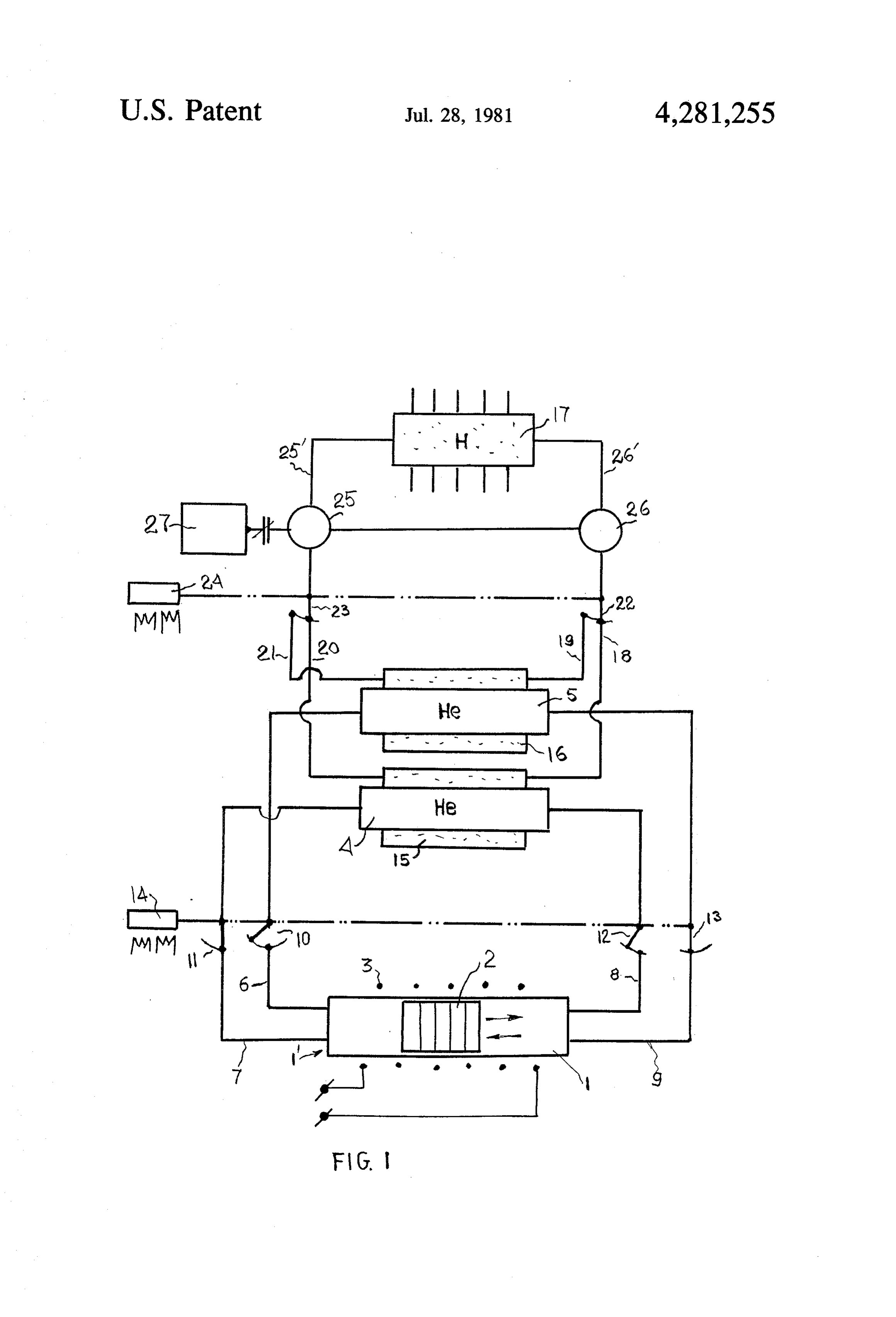
SOURCE OF ENERGY AND A METHOD OF valves 10-13, respectively. A control element 14, such GENERATING ENERGY as an electromagnet 14 operates for actuating the switches 10-13 so as to switch respective valves to
Background of the invention
respective positions thereof.
A receiver 17 accommodates a gaseous inedium, such
The present invention relates to a source and method as hydrogen, which is compressed to some hundreds of generating energy. atmospheres. It communicates with the inner passages A plurality of sources of energy and methods of gen of the jackets 15 and 16 by means of conduits 18, 20 and erating energy have been proposed and used in practice. 19, 21, respectively. The valves 22 and 23 are located in The known sources and method are not satisfactory in 10 the conduits 18,19 and 20, 21, respectively. The valves some aspects. 22 and 23 are actuated by a control element 24, such as SUMMARY OF THE INVENTION an electromagnet, so as to move a respective one of these valves to a respective position.
Accordingly, it is an object of the present invention to provide a new source of energy and a new method of 25Ais pump generating energy which have some advantages as com 25 is connectedassociated arranged with a conduit 25". The motor with a generator 27 so as to operate the pared with the prior art. latter.
In keeping with these objects, and with others which The energy source arrangement operates in the fol will become apparent hereinbelow, one feature of the lowing manner.
present invention resides in a source of energy arrange 20
Hydrogen which is accommodated in the receiver 17 ment which has a mover having a housing and an ele is heated under the action of a surrounding medium ment movable in the housing, container means accom modating gas and so arranged that the gas is heated inasmuch as the receiver 17 is exposed to the latter. The under the action of a surrounding medium, and commu thus-heated hydrogen is supplied from the receiver 17 nicating means communicating the container means 25 into the jacket of the container 4 so as to heat helium with the housing of the mover. The gas heated in the which is accommodated in the container 4. This will be container means is fed into the mover, expands.therein explained in detail later on. Helium which is com and moves the movable element. At the same time, the pressed in the container 4 and heated to 20-30 K. is gas is cooled during the expansion and partially con fed from the container 4 through the conduit 7 into a densed. Then, the gas is again fed from the container 30 left part of the housing 1 of the mover 1", as considered means in an opposite part of the mover and moves the in the drawing. It expands and thereby moves the mov movable element in an opposite direction. Thereby, the able element or piston 2 to the right. At the same time, gas which has been cooled and partially condensed in the expanded helium is cooled and partially condensed. the previous step is expelled by the movable element After this, the valve 11 is switched off, whereas the into the container means wherein the gas is again heated 35 valve 12 is switched on so that the compressed and under the action of the surrounding medium. Another heated helium is again fed from the container 4 through feature of the present invention is to provide a method the conduit 8 into a right part of the housing 1 of the of generating energy including the above-mentioned mover 1'. The thus-fed helium expands and moves the steps. piston to the left. At the same time, it also is cooled and The novel features which are considered as charac partially condensed in the right part of the housing. The teristic for the present invention are set forth in particu helium which was accummulated in the left side of the lar in the appended claims. The invention itself, how housing during the previous step and is in cooled and ever, both as to its construction and its method of opera partially condensed condition, is expelled by the piston tion, together with additional objects and advantages 2 which now moves to the left and travels through the thereof, will be best understood from the following 45 conduit 6 into the container 5. During the expansion of description of specific embodiments when read in con the helium admitted in both parts of the housing 1 and nection with the accompanying drawings. the movements of the piston 2 in the respective direc BRIEF DESCRIPTION OF THE DRAWING tions electric current is generated in the winding 3 which current can be supplied to a consumer. It is to be
The single FIGURE of the drawing is a schematic 50 noted that the winding is constituted by a superconduc view showing a source of energy arrangement in accor tive material.
dance with the present invention. As mentioned hereinabove, the receiver 17 accom DESCRIPTION OF A PREFERRED modates hydrogen which is heated under the action of EMBODIMENT the surounding medium. The hydrogen is heated to 55 gaseous state and is fed to the motor 25 so as to move a
An energy source arrangement in accordance with working element thereof, such as a rotor. The latter the present invention has a mover which is indentified actuates the generator 27 which generates electric cur in toto by reference numeral 1 and has a housing 1 and rent to be supplied to a consumer. At the same time, the an element 2 which is movable in an inner chamber hydrogen becomes cooled in the motor 25 to a tempera bounded by the housing 1. A winding 3 may be wound 60 ture which, however, is higher that that of the helium about the housing 1 of the mover 1. accommodated in the container 4. The thus-cooled Two containers 4 and 5 are provided adapted to ac hydrogen which is also partially compressed and is in commodate helium which is compressed to about gaseous state is supplied into the jacket 16 of the con 200-350 atm and cooled to about 20-30 K. The con tainer 5 and heats the helium accommodated therein, tainers 4 and 5 have heat-exchange elements, such as 65 e.g.
jackets 15 and 16 which bound inner passages. The underreceived from the mover 1'. The hydrogen liquifies containers 4 and 5 communicate with the housing 1 of whereas the heliumofevaporates the action a heat exchange with the helium, the mover i by means of conduits 6-9 provided with compressed. The heated and and becomes heated and compressed helium is 4 thereafter supplied from the container 5 through the ings into said mover to move said movable element conduit 9 so as to continue the process. The liquified in one direction whereby the helium is cooled and hydrogen is pumped by the pump 26 into the receiver partially condensed, then the heated helium is fed 17. Thus, the containers 4 and 5 perform their functions through another opening from the same container is an alternate order. into the housing of said mover so that it moves said It is to be understood that the arrangement may have movable element in an opposite direction and ex only one, or more than two containers for accommodat pels the cooled and partially condensed helium ing helium. The winding 3 may be ommitted so that the from said mover into one opening of another con piston 2 performs displacement of an additional element tainer wherein the helium is to be again heated to to thereby perform a work. The receiver 17 may also O thereafter be fed through another opening of said serve for actuating an additional element, such as a other container into said housing of said motor. steam engine in response to a temperature differential 2. An arrangement as defined in claim 1, wherein said between the temperature of incoming cooled hydrogen movable element of said mover is constituted by a ferro in one part of the receiver and outgoing heated hydro magnetic material; and further comprising a winding gen in another part thereof. Energy which is released by 15 which is wound about said housing of said mover so gas when it is supplied into the mover in compressed that electric current is generated in said winding when state exceeds the energy which is needed for returning said movable element moves in said housing under the the gas into the container if the gas has at least partially action of the gas received therein. condensed while expanding. The thus-produced differ 3. An arrangement as defined in claim 2, wherein said ential of energy is compensated by the surrounding movable element is constituted by a material which has medium, particularly be means of absorption of heat in chracteristics of a permanent magnet. the receiver 17. 4. An arrangement as defined in claim 1; and further It will be understood that each of the elements de comprising an additional element arranged for accom scribed above, or two or more together, may also find a modating an additional gaseous medium and operative useful application in other types of constructions from 25 to heat said additional gaseous medium under the action the types described above. of the surrounding medium and to thereafter supply the While the invention has been illustrated and de thus-heated additional gaseous medium into said con scribed as embodied in a particular source of energy and tainers to thereby heat the helium accommodated in the a method of generating energy, it is not intended to be latter.
limited to the details shown, since various modifications 30 5. An arrangement as defined in claim 4, wherein and structural changes may be made without departing each of said containers is provided with an outer jacket in any way from the spirit of the present invention. bounding a passage, said additional element communi Without further analysis, the foregoing will so fully cating with said passages of said containers so that said reveal the gist of the present invention that others can additional gaseous medium travels from said additional be applying current knowledge readily adapt it for vari 35 element into said passages to thereby heat the helium ous applications without ommitting features that from accommodated in said containers, the standpoint of prior art, fairly constitute essential 6. An arrangement as defined in claim 5; and further characteristics of the generic or specific aspects of the comprising a motor, said additional element communi present invention. cating with said motor so as to supply said additional What is claimed as new and desired to be protected gaseous medium to the latter whereby said motor is by Letters Patent is set forth in the appended claims: actuated whereas the additional gaseous medium is 1. An energy source arrangement, comprising cooled during operation of said motor to a temperature a mover having a housing: which is higher than that of the helium accmmodated in container means accommodating helium, said con said containers; and further comprising further commu tainer means being so arranged that the helium 45 nicating means arranged for communicating said motor accommodated therein is heated under the action with said passages of said containers so that said addi of surrounding medium, said container means in tional gaseous medium after being cooled in said motor cluding two containers each having two oppositely travels into said passages of said containers to thereby located openings; heat the helium accmmodated in the latter due to the communicating means communicating said container 50 differential between the temperatures of the helium and means with said mover so that the thus-heated the additional gaseous medium.
helium travels through said communicating means 7. An arrangement as defined in claim 1, wherein said from said container means into said housing of said container means is arranged for accommodating helium mover wherein the helium expands and moves said cooled and compressed conditions.
movable element and during this the helium be 55 8. An arrangement as defined in claim 1, wherein said comes cooled and partially condensed, said com additional element is arranged for accommodating hy municating means being further arranged so that drogen in compressed condition.
the thus-cooled and partially condensed helium 9. A method of generating energy, comprising the thereupon travels from said housing of said mover steps of back into said container means without being exter 60 providing a nover having a housing and an element nally cooled to be again heated in the latter under which is movable in the housing; the action of the surrounding medium, said com accommodating helium in container means including municating means including four conduits each two containers each having two oppositely located communicating one of said openings of one of said openings and provided with four conduits each containers with said housing of said mover; and 65 communicating one of said openings of one of said actuating means operative for actuating said commu containers with said housing of said mover; nicating means so that the heated helium is fed heating the helium accommodated in the container from one of said containers through one of its open under the action of surrounding medium;
Page 5scan →
supplying the thus-heated helium into said housing of said mover so that the helium expands and moves said movable element and at the same time the helium is cooled and partially condensed during the expansion; and withdrawing the thus-cooled and partially condensed helium from said housing of said mover into said container means without cooling by external cool ing means so as to again heat the helium in the latter under the action of the surrounding medium, O said supplying and withdrawing steps including feeding the heated helium from one of said contain ers through one of its openings into said mover to move said movable element in one direction whereby the helium is cooled and partially con densed, the feeding the heated helium through another opening from the same container into said housing of said mover so that it moves said mov able element in an opposite direction and expels the cooled and partially condensed helium from said mover into one opening of another container wherein the helium is to be again heated to thereaf ter be fed through another opening of said other container into said housing of said mover.
Provenance
- Collection
- Patents citing this work
- Pages
- 5
- Method
- pdftotext (the PDF's own text layer) + pdftoppm 300dpi page scans
- Patent office record
- patents.google.com →
- Source
- Google Patents citing-documents table
- Assignee
- Sherman Victor L
- Published
- 1981-07-28
- Transcribed from
- patentimages.storage.googleapis.com →